EIGRP Metric Problem
EIGRP uses a composite metric composed of bandwidth, delay, reliability, load, and MTU. The metric is calculated using the formula:
Metric = [(K1 x Bw) + (K2 x Bw) + (K3 x Delay)] + K5 (256 – Load)(Reliability + K4)
in which Bw refers to bandwidth.
In EIGRP, K2 = K4 = K5 = 0 and K1 = K3 = 1, by default. As a result, the formula reduces to:
Metric = Bw + Delay Bw = 10,000,000 x 1
.
Bandwidth in Kbps
Delay = 100 x (delay in ms)
The final metric used in EIGRP is:
Metric = 10,000,000 x 1 + 100 (delay in ms)
Bandwidth in Kbps
Bandwidth and delay are configurable parameters at the router interfaces with default values. For example, the default bandwidth value of a serial interface is that of a T1 link. Consider the example depicted in Figure 8.6 to detect and troubleshoot issues related to the EIGRP metric. In Figure 8.6, routers A2, A3, and A4 are directly connected to router A1.
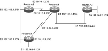
Figure 8.6: An EIGRP network depicting metric problems.
Observation
Data traffic moving between A1 and A4 is erratic, with some packets getting dropped from time to time. This erratic behavior was reported by users accessing the Web server 192.168.4.2. The Web server is directly connected to A4.
Problem Isolation
The steps to isolate the metric problem are:
-
Check if there is any problem in the route availability in the routing table and the topology table. This is verified by using the show ip route 192.168.4.0 and show ip eigrp topology | inc 192.168.4.0 commands. The output for the show ip route 192.168.4.0 command is shown in Listing 8.28.
Listing 8.28 Output for the show ip route 192.168.4.0 Command at A1

A1#show ip route 192.168.4.0 Routing entry for 192.168.4.0/24 Known via "eigrp 300", distance 90, metric 1787392, type internal Redistributing via eigrp 100 Last update from 10.10.3.1 on Serial0, 1d06h ago Routing Descriptor Blocks: * 10.10.3.1, from 10.10.3.1, 1d06h ago, via Serial0 Route metric is 1787392, traffic share count is 1 Total delay is 21000 microseconds, minimum bandwidth is 2048 Kbit Reliability 254/255, minimum MTU 1500 bytes Loading 1/255, Hops 1
The output for the show ip eigrp topology | inc 192.168.4.0 command at A1 is:
A1#show ip eigrp topology | inc 192.168.4.0 P 192.168.4.0/24, 1 successors, FD is 1787392
-
Make sure there is no neighbor relationship problem by using the A1#show ip eigrp neighbors command.
-
Make sure the transmission link connecting the rest of the EIGRP network with A4, which is terminated at interface Serial 0, has no errors. This is verified by using the show interface Serial 0 command. Listing 8.29 shows the output for the show interface Serial 0 command for A1.
Listing 8.29 Output of the show interface Serial 0 Command for A1
A1#show interface Serial 0 Serial0 is up, line protocol is up Hardware is HD64570 Description: WAN link for Router A4 Internet address is 10.10.3.2/30 MTU 1500 bytes, BW 1544 Kbit, DLY 20000 usec, reliability 255/255, txload 1/255, rxload 1/255 Encapsulation HDLC, loopback not set Keepalive set (10 sec) Last input 00:00:00, output 00:00:00, output hang never Last clearing of "show interface" counters never Input queue: 0/75/3134350/0 (size/max/drops/flushes); Total output drops: 11 Queueing strategy: weighted fair Output queue: 0/1000/64/0 (size/max total/threshold/drops) Conversations 0/11/256 (active/max active/max total) Reserved Conversations 0/0 (allocated/max allocated) 5 minute input rate 13000 bits/sec, 29 packets/sec 5 minute output rate 2000 bits/sec, 3 packets/sec 115001192 packets input, 4155732628 bytes, 272 no buffer Received 425130 broadcasts, 0 runts, 0 giants, 0 throttles 0 input errors, 0 CRC, 0 frame, 0 overrun, 0 ignored, 0 abort 21650119 packets output, 3170761599 bytes, 0 underruns 0 output errors, 0 collisions, 0 interface resets 0 output buffer failures, 0 output buffers swapped out 0 carrier transitions DCD=up DSR=up DTR=up RTS=up CTS=up
The command output shows errors in the link. EIGRP routing updates are exchanged without any problem, but the data traffic gets hampered.
-
Check the configured bandwidth parameter at the interface by using the show interface Serial 0 command. The output for the show interface Serial 0 command for A1 is shown in Listing 8.30.
Listing 8.30 Output for the show interface Serial 0 Command for A1
A1#show interface Serial 0 Serial0 is up, line protocol is up Hardware is HD64570 Description: WAN link for Router A4 Internet address is 10.10.3.2/30 MTU 1500 bytes, BW 1544 Kbit, DLY 20000 usec, reliability 255/255, txload 1/255, rxload 1/255 Encapsulation HDLC, loopback not set Keepalive set (10 sec) Last input 00:00:00, output 00:00:00, output hang never Last clearing of "show interface" counters never Input queue: 0/75/3134350/0 (size/max/drops/flushes); Total output drops: 11 Queueing strategy: weighted fair Output queue: 0/1000/64/0 (size/max total/threshold/drops) Conversations 0/11/256 (active/max active/max total) Reserved Conversations 0/0 (allocated/max allocated) 5 minute input rate 13000 bits/sec, 29 packets/sec 5 minute output rate 2000 bits/sec, 3 packets/sec 115001192 packets input, 4155732628 bytes, 272 no buffer Received 425130 broadcasts, 0 runts, 0 giants, 0 throttles 0 input errors, 0 CRC, 0 frame, 0 overrun, 0 ignored, 0 abort 21650119 packets output, 3170761599 bytes, 0 underruns 0 output errors, 0 collisions, 0 interface resets 0 output buffer failures, 0 output buffers swapped out 0 carrier transitions DCD=up DSR=up DTR=up RTS=up CTS=up
In Listing 8.30, the bandwidth configured for the interface is 1544 KB. There can be two conditions of a faulty bandwidth configuration in EIGRP. They are:
-
Bandwidth is not configured. EIGRP uses a maximum of 50% of the link bandwidth for the routing packets, by default. The default of a serial link is a T1 with a bandwidth of 1.5 mbps. In this case, the link is a fractional T1 with a bandwidth of 768 Kbps. The configured bandwidth being 1.5 mbps, EIGRP reserves 750 Kbps for itself, which leaves less than 50 Kbps for data traffic causing dropping of traffic. Bandwidth is configured correctly using the commands
A1(config)#interface S0 A1(config-if)#bandwidth 768
-
Bandwidth is incorrectly configured. Sometimes, a value of bandwidth other than the actual value is configured in serial links to manipulate the metric value to influence route selection in routing protocols. In Figure 8.6, both serial links are 56 Kbps bandwidth. To choose the path via A2 over the path via A4 to network 192.168.1.0/24, the bandwidth parameter of the link to A4 is set at a higher value of 224 Kbps. Out of this, 50% (that is, 112 Kbps) may be used for
-
EIGRP traffic, which is more than the actual bandwidth of the link. This condition causes congestion of the link. To overcome this condition, without affecting the desired effect on path selection process, you can use the commands
A1(config)#interface Serial0 A1(config-interface)#ip bandwidth-percent eigrp 100 12
These commands restrict the maximum percentage of the configured value of bandwidth to be used in EIGRP to 12% (27 Kbps), which is around 50% of the actual bandwidth.
EAN: 2147483647
Pages: 130