| The IEEE 802.11 MAC sub-layer protocol structure follows the IEEE LMSC model, and thus has no higher-layer protocol demultiplexing features of its own. Therefore, the IEEE 802.11 MAC sub-layer protocol relies on the LLC sub-layer[5] headers to perform the higher layer protocol de-multiplexing function. [5] The LLC sub-layer consists of the LLC sub-layer protocol, and optionally the SNAP sub-layer protocol.
| Besides defining the format of a MAC-layer frame, the IEEE 802.11 MAC sub-layer protocol specification must also define the means by which stations gain access to and share the medium, such that it is shared as fairly as possible. Once a wireless station (frequently abbreviated as "STA" in the wireless LAN standards) has successfully joined a wireless LAN, it must obey the "rules of the road" that govern access to the wireless medium. Chapter 5, Dissection of a Probe Response MMPDU, describes the "access" aspects of the IEEE 802.11 MAC sub-layer protocol, while this chapter focuses mostly on the frame-oriented aspects. This division of content is admittedly somewhat arbitrary, but the two subjects deserve to be described independently. IEEE 802.11's MAC sub-layer access control protocol is comprised of a number of mechanisms that are collectively known as Carrier Sense Multiple Access with Collision Avoidance (CSMA/CA). The IEEE 802.11 standard refers to CSMA/CA, along with certain related procedures, as the Distributed Coordination Function (DCF). The IEEE 802.11 MAC sub-layer protocol uses CSMA/CA in a manner similar to the way that Ethernet uses its Carrier Sense Multiple Access with Collision Detection (CSMA/CD), in that CSMA/CD's rules were defined to govern medium access in half-duplex shared (i.e., non-switched) Ethernet networks. |
All IEEE 802.11 frames begin with the two-octet Frame Control (FC) field, the structure of which is depicted in Figure 4-3.[6] [6] Excerpted from IEEE Std. 802.11™-1999, copyright 1999, with the naming of Bit 14 shown as modified by IEEE 802.11i (work in progress; subject to change before publication). All rights reserved.
Figure 4-3. IEEE 802.11's Frame Control field[6] 
The Protocol Version (bits 0 and 1) defined by IEEE 802.11-1999 is "0x00". The Type (bits 2 and 3) and Subtype (bits 4 through 7) fields define the format of the subsequent frame, and are listed in Figure 4-4. Figure 4-4. Management, Control, and Data Frames in IEEE 802.11[7] 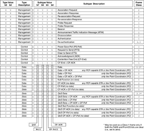
[7] Adapted from IEEE Std. 802.11™-1999, copyright 1999. All rights reserved. Augmented by draft 4.4 of IEEE 802.11e (work in progress, subject to change before publication.).
The frame's two-bit Type subfield permits a total of four IEEE 802.11 frame types, of which three were defined in IEEE 802.11-1999, viz.: Bit 3 (0) + Bit 2 (0) Management Bit 3 (0) + Bit 2 (1) Control Bit 3 (1) + Bit 2 (0) Data Bit 3 (1) + Bit 2 (1) Undefined
The bit ordering within multi-bit fields in Figure 4-3 are in "little-endian" form (which matches the IEEE 802.11-1999 specification), but Figure 4-4 displays them in "big-endian" form, since the author finds that more easily understandable. In order to ease conversion between the two formats, Figure 4-4 includes the bit position numbers at the top of the chart. Chapter 5 contains several detailed examples that should help clarify the relationship between the different representations. Through the use of the 4-bit Subtype field, each of IEEE 802.11's frame Types may have up to 16 Subtypes. The Subtype field is stored in the fourth through seventh bit positions of the FC field. When the Type subfield indicates a Data frame, each of the four bits of the FC's Subtype subfield has a particular meaning (whereas the subtypes of the Management and Control Types are just numbers, with no structure). In Figure 4-4, the meanings of each bit offset within the Subtype field of the Data Type is illustrated by enclosing each bit in a vertical box with the label at the bottom. | Only half of the Data Subtypes were defined in the IEEE 802.11-1999 standard, with the remainder being reserved. These have now been allocated to the IEEE 802.11 WG's TG "e," which is enhancing the MAC sub-layer protocol to provide features that can support QoS. These eight Data subtype values that were originally reserved mirror the functions of the first eight, except that these formerly reserved Data subtypes now all denote QoS-enhanced frames. The Data frame types in italics are associated with the IEEE 802.11e TG,[8] and will only become valid once that standard has been approved, probably not in 2003. |
[8] The working title for the IEEE 802.11e draft standard is "Medium Access Control (MAC) Enhancements for Quality of Service (QoS)."
Three-quarters of the Data subtypes are only valid during PCF mode (see Chapter 6). PCF mode, in which the AP polls the STAs for frames, was an early attempt at providing a latency-bounded MAC service. Any Data subtypes with "CF" in their names are used only during Contention-Free operation; in other words, only when the BSS is operating in PCF mode. Of these, half of them may only be sent only by the Point Coordinator (PC) function in the AP, whereas the other half may either be sent by the Point Coordinator (PC) or by any other STAs in PCF mode. Given that PCF mode is virtually not implemented, these subtypes should be rarely seen in the real world. Summary of the Frame Control Field Bits 0 and 1 (which comprise the Protocol Version field) have been defined by IEEE 802.11-1999 as "0x00". The Type (bits 2 and 3) and Subtype (bits 4 through 7) fields define the format of the subsequent frame. Bit 8 (the "ToDS"), and bit 9 (the "FromDS" bit), will be covered in Chapter 6. These two bits control the interpretation of the "Address" fields in the MPDU and MMPDU headers. Bit 10, the "More Frag." (i.e., More Fragments) bit, indicates (if it is set to "1") that this MPDU or MMPDU is a fragment of a larger MSDU or MMPDU, and that this is not the last fragment. If the bit is clear, then this frame is the last fragment, or the frame was never fragmented. Note that when a STA performs MAC-layer fragmentation, each MSDU or MMPDU fragment is transmitted in order, and is individually acknowledged before the next fragment of that MSDU or MMPDU can be sent. Bit 11, the "Retry" bit, is set when this MPDU or MMPDU is a retransmission of an earlier MPDU or MMPDU. The Retry bit allows the receiving STA to detect and eliminate any duplicate MPDUs or MMPDUs that it happens to receive. If a STA receives a MPDU or MMPDU and acknowledges it, but the ACK control frame does not reach the sending STA, then the sender will retransmit the frame with the Retry bit set. In this case, the receiving STA will get more than one copy of the frame, but only the first copy will have the Retry bit clear, while all the rest will have it set. The receiving STA will be able to use this extra information to ensure that it only receives a single copy of the frame. Bit 12, the "Pwr. Mgt." (i.e., Power Management) bit, is used to indicate what power management state the sending station will enter upon successfully completing the transmission of the current MPDU or MMPDU. When a STA sets this bit, it is advertising that it will be entering "power-save" mode after it completes sending this frame and it receives the ACK indicating that the frame was received. If this bit is clear, the STA is going to remain in an active state. Bit 13, the "More Data" bit, is used when talking to a STA that is in power-save mode, to let it know that after this frame, there are still more frames buffered for it. Upon receiving a frame with this bit set, the receiving STA could choose to stay awake a little longer to collect the frames that are queued for delivery to it. If the receiving STA chooses to conserve power and doze anyway, the AP will buffer the frames until the receiving STA's next scheduled awake time. Bit 14, the "Prot. Frm." (i.e., Protected Frame) bit,[9] is used to indicate that a frame is protected by one of the cipher suites supported by IEEE 802.11 (see Chapter 7, Security Mechanisms for Wireless LANs, for more details). [9] This bit was formerly known as the "WEP" bit (Wired-Equivalent Privacy) in the original IEEE 802.11-1999 standard, but the IEEE 802.11i TG is changing its name (as indicated in the text). The author has chosen to use the newer name, but to keep the original name alive via this footnote. Purists may object to my referencing a draft document, but the author is willing to take the risk that IEEE 802.11i will be ratified during the shelf life of this book.
Bit 15, the "Ord." Bit, is set to indicate that a given MSDU is being sent using the "strictly ordered" service class provided by the 802.11 MAC. The other service class type is "re-orderable multicast." If an MSDU is being sent with the Order bit set, then no other MSDUs may be sent to a STA until this MDSU has been completely transmitted (e.g., in the case where an AP has multiple frames buffered for that STA, any frames with the Order bit set must be transmitted in order). A STA may not simultaneously receive traffic using the strictly ordered service class if it has already elected to use power management. If a STA wishes to receive frames of the strictly ordered service class, it may not doze.
|