Section 3.2. The Transformation Pipeline
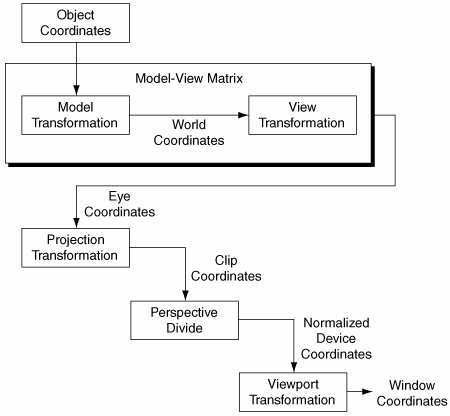
3.2. The Transformation PipelineThe OpenGL transformation pipeline (see Figure 3-2) transforms application vertices into window coordinates, where they can be rasterized. Like all 3D graphics systems, OpenGL uses linear algebra; it treats vertices as vectors and transforms them by using vector-matrix multiplication. The transformation process is called a pipeline because geometry passes through several coordinate systems on the way to window space. Each coordinate system serves a purpose for one or more OpenGL features. Figure 3-2. The OpenGL transformation pipeline.
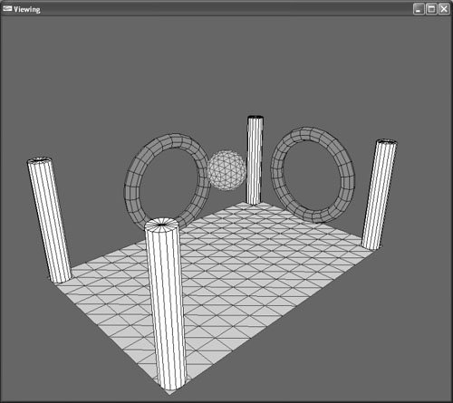
For each stage of the transformation pipeline, this section describes the characteristics of that coordinate system, what OpenGL operations are performed there, and how to construct and control transformations to the next coordinate system in the pipeline. Graphics programmers new to OpenGL are often surprised to learn that there is no world-coordinate system in the OpenGL transformation pipeline. This is because there are no OpenGL features that require computation in a world-coordinate system. For this reason, world coordinates are an application construct. Most applications have a concept of world coordinatessetting the view position, for example, is done in terms of world coordinatesand the discussion that follows describes how the OpenGL transformation pipeline accommodates this requirement. 3.2.1. Object CoordinatesApplications specify vertices in object coordinates. The definition of object coordinates is entirely up to the application. Some applications render scenes that are composed of many models, each created and specified in its own individual coordinate system. Consider the Viewing example program (see Figure 3-3), available from this book's Web site. Figure 3-3. The Viewing example program. The code positions the cylinders, tori, sphere, and plane using different model transformations for each object.
The Viewing example renders a scene composed of a plane, a sphere, two tori, and four columns. Each of these objects is defined around the same object-space origin. The Viewing example, however, uses a model transformation to position and orient the objects in the world-coordinate system. Without the model transformation, object coordinates wouldn't exist, and all parts of a scene would have to be created in world coordinates, which would prohibit model reuse. 3.2.2. The Model TransformationThe model transformation transforms geometry from object to world coordinates. Applications store both the model and view transformations in the model-view matrix as a single concatenated matrix. Applications almost always use model transformations to move geometry from a local object-coordinate system to a global world-coordinate system. Typically, applications use the glRotate*(), glScale*(), and glTranslate*() functions to position and orient geometry and models in the world. In addition to orienting geometry statically, applications use model transformations to create animations by moving objects dynamically from one frame to the next. Applications often use multiple nested model transformations to transform geometry into a world-coordinate system. Consider how you would create an orrery, or model of the solar system, in which the Moon is located relative to the Earth, and the Earth in turn is located relative to the Sun. The Transformation example program (see Figure 3-4) demonstrates how to use nested model transformations to create and animate this model. Figure 3-4. The Transformation example program. The code positions the Earth relative to the Sun with a translation and rotation model transformation; then it uses a nested translation and rotation to position the Moon relative to the Earth. The rotations change from frame to frame to animate the model.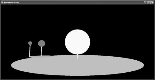 3.2.3. World CoordinatesThe world-coordinate system is an application construct that exists between OpenGL's object- and eye-coordinate systems. If the model-view matrix were split into two transformationsthe model transformation and the view transformationmultiplying object-space coordinates by the model transformation would produce world coordinates, and multiplying those world coordinates by the view transformation would produce eye coordinates. Because OpenGL performs no operations in the world-coordinate system, it's not part of the formal OpenGL transformation pipeline. 3.2.4. The View TransformationIn precise terms, the view transformation is the inverse of a transformation that positions and orients the camera in the application's world-coordinate system. Methods for setting the view transformation are covered in the section "Setting the Model-View Matrix" later in this chapter. Applications store both the model transformation and view transformation in the model-view matrix. Load the view transformation into the model-view matrix first; then post-multiply the model transformations. 3.2.5. Eye CoordinatesOpenGL eye coordinates are defined as follows:
For geometry to be visible in a standard perspective projection, it must lie somewhere along the negative z axis in eye coordinates. Geometry along the positive z axis is behind the viewpoint and, therefore, is not rendered. To view geometry with coordinates in the positive z range, your application needs to translate it into the negative z range using the model-view matrix. In this example, your original geometry in the positive z range is in object coordinates, and the model-view matrix transforms it into eye coordinates. Depending on current state, OpenGL computes lighting, fog, certain texture coordinates, user-defined clipping, and point size from eye-coordinate values. 3.2.6. The Projection TransformationOpenGL multiplies eye coordinates by the projection matrix to produce clip coordinates. The projection matrix defines the size and shape of the view volume and, therefore, determines the portion of eye coordinates that will ultimately be visible. Typically, applications create either perspective or parallel projections. The section "Perspective and Parallel Projections" later in this chapter provides more information on setting the projection transformation. 3.2.7. Clip CoordinatesOpenGL clips primitives that lie outside the view volume in clip-coordinate space. A clip coordinate vertex is within the view volume if its x, y, and z values are all within the w to w range. Application programmers rarely concern themselves with how this actually works. If your application specifies a well-defined projection matrix using glOrtho() or gluPerspective(), clipping will happen as expected; OpenGL clips geometry outside the view volume and performs no further processing on it. 3.2.8. Perspective DivisionOpenGL divides clip coordinate x, y, and z values by the clip-coordinate w value to produce normalized device coordinates. As with clipping, if your application creates a well-defined projection matrix, you don't need to be concerned with the perspective division. It happens automatically if you specify a perspective projection, and it's effectively a no-op if you specify a parallel projection. For perspective projections, the perspective division effectively shrinks distant geometry and expands near geometry. 3.2.9. Normalized Device CoordinatesIn normalized device coordinates, vertex x, y, and z values lie within the 1.0 to 1.0 range. Whereas previous coordinate systems used homogeneous coordinates, with vertices composed of x, y, z, and w values, normalized device coordinates are 3D Cartesian coordinates. OpenGL doesn't perform any operations in normalized device coordinates. It is simply a coordinate system that exists between the perspective division and the viewport transformation to window coordinates. 3.2.10. The Viewport TransformationThe viewport transformation is the final stage in the transformation pipeline. It's a scale and translation that maps the 1.0 to 1.0 normalized device-coordinate cube into window coordinates. Note that this transformation applies not only to x and y values, but also to the z value. The viewport transformation maps normalized device-coordinate z values to the range of acceptable depth buffer values. Applications usually set the viewport when the window changes size. Set the viewport with a call to glViewport(). The section "The Viewport" later in this chapter contains more information. 3.2.11. Window CoordinatesWindow coordinates have their xy origin in the bottom-left corner of the window, and window-coordinate z values extend throughout the depth buffer. Programmers often make the mistake of assuming that window coordinates are integers. OpenGL window coordinates are actually floating-point values; window-coordinate vertices exist at subpixel locations. This is essential for correct rasterization and multisampling. To understand the concept of floating-point window coordinates, you should imagine the window as being the first quadrant of a Cartesian coordinate system with the origin at the bottom-left corner, positive x extending to the right, and positive y extending up. Pixels cover a square area, with integer gridlines corresponding to pixel boundaries. As a gross oversimplification of the rasterization process, OpenGL rasterizes a pixel based on the intersection of the pixel area and the xy floating-point window-coordinate representation of the primitive. It's often convenient to think of depth values as normalized, where 0.0 corresponds to the front of the depth buffer and 1.0 corresponds to the back. Actual depth buffer values are device dependent. 3.2.12. Controlling TransformationsProgrammers should think of the transformation pipeline as OpenGL state that can be manipulated and controlled through OpenGL commands. Applications create model and view transformations in the model-view matrix. Routines commonly used to create model transformations, such as glRotate*(), glScale*(), and glTranslate*(), are described earlier in this chapter. The section "Setting the Model-View Matrix" later in this chapter covers creating the view transformation. Applications specify projections in the projection matrix. The section "Perspective and Parallel Projections" later in this chapter discusses how to do this with the glOrtho() and gluPerspective() commands. In some application environments, setting the viewport isn't necessary. The default viewport setting maps normalized device coordinates to the entire window. If this is your desired behavior, and your window never changes size, you'll never need to set the viewport. In most modern window systems, however, applications set the viewport whenever the window changes size. Changing the viewport is covered in the section "The Viewport" later in this chapter. 3.2.12.1. Minimal TransformationsAlthough professional applications always control the transformation pipeline to some extent, a noteworthy fact is that it's possible to render geometry without setting any transformation parameters. The model-view and projection matrices default to the identity matrix, and the viewport transformation defaults to the full window. If your application doesn't change these defaults, object coordinates and normalized device coordinates are identical, and OpenGL renders any geometry your application sends that is between 1.0 and 1.0 in x, y, and z. Professional applications don't do this, but sometimes it's helpful to start with a simplified transformation pipeline when debugging. 3.2.12.2. Obtaining Transformed ValuesApplications sometimes need the window coordinate of a vertex without rendering it, or given a window coordinate, applications need the corresponding object-coordinate value. GLU provides two routines that fulfill this need: gluProject() and gluUnProject().
flylib.com © 2008-2017. If you may any questions please contact us: flylib@qtcs.net |