When an application submits a primitive to OpenGL for rendering, OpenGL uses the current state to determine what operations to perform on the primitive data.
OpenGL supports a variety of flexible features that affect the appearance of rendered geometry. Some of the more complex operations, such as viewing, lighting, and texture mapping, are covered in their own chapters. This section explains a few of the simpler operations. OpenGL® Programming Guide and OpenGL® Shading Language present the complete OpenGL feature set.
2.3.1. Clearing the Framebuffer
Before issuing the first rendering command and periodically thereafter (typically, at the start of each frame), applications need to clear the contents of the framebuffer. OpenGL provides the glClear() command to perform this operation.
void glClear( GLbitfield mask );
Clears the framebuffer contents. mask is one or more bit values combined with the bitwise OR operator that specify the portion of the framebuffer to clear. If GL_COLOR_BUFFER_BIT is present in mask, glClear() clears the color buffer. If GL_DEPTH_BUFFER_BIT is present in mask, glClear() clears the depth buffer. If both bit values are present, glClear() clears both the color and depth buffers.
glClear() can also clear other parts of the framebuffer, such as the stencil and accumulation buffers. For a complete list of bit values accepted by glClear(), see "glClear" in OpenGL® Reference Manual.
Typically, applications clear both the color and depth buffers with a single glClear() call at the start of each frame.
Clearing multiple buffers with a single glClear() call is more efficient than clearing separate buffers with separate glClear() calls. There are rendering techniques that require clearing the depth and color buffer separately, however. Try to clear both buffers at the same time when possible.
Your application controls the color that glClear() writes to the color buffer by calling glClearColor().
Specifies the clear color used by glClear(). red, green, blue, and alpha are four values specifying an RGBA color value and should be in the range 0.0 to 1.0. Subsequent calls to glClear() use this color value when clearing the color buffer.
glClearColor() sets the current clear color, which is black by default (0.0, 0.0, 0.0, 0.0). This is adequate for some applications. Applications that set the clear color usually do so at program init time.
Note that not all framebuffers contain an alpha channel. If the framebuffer doesn't have an alpha channel, OpenGL effectively ignores the alpha parameter when clearing. Specify whether your framebuffer contains an alpha channel with the GLUT command glutInitDisplayMode() or platform-specific framebuffer configuration calls.
You can also specify the depth value written into the depth buffer by glClear(). By default, glClear( GL_DEPTH)BUFFER_BIT ) clears the depth buffer to the maximum depth value, which is adequate for many applications. To change this default, see "glDepthValue" in OpenGL® Reference Manual.
2.3.2. Modeling Transformations
Complex 3D scenes typically are composed of several objects or models displayed at specific locations within the scene. These objects are routinely modeled in their own modeling-coordinate system and transformed by the application to specific locations and orientations in the world-coordinate system. Consider a scene composed of an aircraft flying over a terrain model. Modelers create the aircraft by using a modeling software package and might use a coordinate system with the origin located in the center of the fuselage, with the aircraft nose oriented toward positive y and the top of the aircraft oriented toward positive z. To position and orient this aircraft model relative to the terrain model, the application must translate it laterally to the correct position and vertically to the correct altitude, and orient it to the desired pitch, roll, and aircraft heading.
OpenGL transforms all vertices through a geometry pipeline. The first stage of this pipeline is the modeling transformation stage. Your application specifies modeling transformations to position and orient models in the scene. To manage the transformation of your geometry effectively, you need to understand the full OpenGL transformation pipeline. See Chapter 3, "Transformation and Viewing," for details.
2.3.3. Smooth and Flat Shading
To simulate a smooth surface, OpenGL interpolates vertex colors during rasterization. To simulate a flat or faceted surface, change the default shade model from GL_SMOOTH to GL_FLAT by calling glShadeModel( GL_FLAT ).
void glShadeModel( GLenum mode );
Specifies smooth or flat shading. mode is either GL_SMOOTH or GL_FLAT. The default value of GL_SMOOTH causes OpenGL to use Gouraud shading to interpolate vertex color values during rasterization. GL_FLAT causes OpenGL to color subsequent primitives with the color of the vertex that completes the primitive.
To determine the color of a primitive in flat shade mode, OpenGL uses the color of the vertex that completes the primitive. For GL_POINTS, this is simply the color of the vertex. For all line primitives (GL_LINES, GL_LINE_STRIP, and GL_LINE_LOOP), this is the color of the second vertex in a line segment.
For GL_TRIANGLES, OpenGL colors each triangle with the color of every third vertex. For both GL_TRIANGLE_STRIP and GL_TRIANGLE_FAN, OpenGL colors the first triangle with the color of the third vertex and colors each subsequent triangle with the color of each subsequent vertex.
For GL_QUADS, OpenGL colors each quadrilateral with the color of every fourth vertex. For GL_QUAD_STRIP, OpenGL uses the color of the fourth vertex to color the first quadrilateral in the strip and every other vertex thereafter to color subsequent quadrilaterals.
For GL_POLYGON, OpenGL colors the entire polygon with the color of the final vertex.
2.3.4. Polygon Mode
It shouldn't be a surprise that filled primitives are drawn filled by default. Applications can specify, however, that OpenGL render filled primitives as lines or points with the glPolygonMode() command.
void glPolygonMode( GLenum face, GLenum mode );
Specifies the rendering style for filled primitives. mode is GL_POINT, GL_LINE, or GL_FILL; and face must be GL_FRONT, GL_BACK, or GL_FRONT_AND_BACK to specify whether mode applies to front- or back-facing primitives, or both.
Polygon mode is useful for design applications that allow the user to switch between solid and wireframe rendering. Many applications also use it to highlight selected primitives or groups of primitives.
2.3.5. The Depth Test
OpenGL supports the depth test (or z-buffer) hidden-surface-removal algorithm (Catmull 1974).
To use the depth test, your application must allocate a depth buffer when creating its display window. In GLUT, use a bitwise OR to include the GLUT_DEPTH bit in the parameter to glutInitDisplayMode() before calling glutCreateWindow(). Applications typically specify a double-buffered RGB window with a depth buffer by using the following call:
The depth test is disabled by default. Enable it with glEnable( GL_DEPTH_TEST ).
The depth-test feature discards a fragment if it fails to pass the depth comparison test. Typically, applications use the default comparison test, GL_LESS. In this case, a fragment passes the depth test if its window-space z value is less than the stored depth buffer value. Applications can change the default comparison test by calling glDepthFunc(). The GL_LEQUAL comparison test, which passes a fragment if its z value is less than or equal to the stored depth value, is useful in multipass algorithms. See "glDepthFunc" in OpenGL® Reference Manual for a complete description of this function.
OpenGL executes commands in the order in which they are sent by the application. This rule extends to rendering primitives; OpenGL processes vertex array rendering commands in the order in which they are sent by the application and renders primitives within a single vertex array in the order that the array indices specify. This feature allows applications to use the painter's algorithm to remove hidden surfaces, rendering a scene in order of decreasing distance. When applications disable the depth test, the first primitives rendered are overwritten by those that are rendered later.
2.3.6. Co-Planar Primitives
You might expect that fragments with the same window-space x and y values from co-planar primitives would also have identical window-space z values. OpenGL guarantees this only under certain circumstances.[4] When co-planar filled primitives have different vertices, floating-point roundoff error usually results in different window-space z values for overlapping pixels. Furthermore, because line primitives don't have plane equations, it's impossible for unextended OpenGL to generate identical window-space z values for co-planar lines and filled primitives. For this reason, setting glDepthFunc( GL_LEQUAL ) is insufficient to cause co-planar primitives to pass the depth test.
[4] See appendix A, "Invariance," in The OpenGL Graphics System.
Applications can apply a depth offset to polygonal primitives to resolve coplanarity issues.
void glPolygonOffset( GLfloat factor, GLfloat units );
Specifies parameters for altering fragment depth values. OpenGL scales the maximum window-space z slope of the current polygonal primitive by factor, scales the minimum resolvable depth buffer unit by units, and sums the results to obtain a depth offset value. When enabled, OpenGL adds this value to the window-space z value of each fragment before performing the depth test.
The depth offset feature is also referred to as polygon offset because it applies only to polygonal primitives.
Depth offset applies to polygonal primitives but can be separately enabled and disabled for each of the three polygon modes. To enable depth offset in fill mode, call glEnable( GL_POLYGON_OFFSET_FILL ). Use GL_POLYGON_OFFSET_POINT and GL_POLYGON_OFFSET_LINE to enable or disable depth offset for point and line mode, respectively.
Typically, applications call glPolygonOffset( 1.f, 1.f ) and glEnable( GL_POLYGON_OFFSET_FILL ) to render filled primitives that are pushed back slightly into the depth buffer, then disable depth offset and draw co-planar geometry.
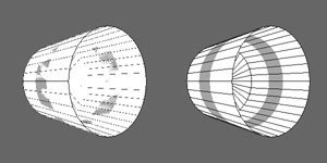
Figure 2-4 illustrates rendering co-planar primitives with and without depth offset.
Figure 2-4. This figure illustrates the result of rendering co-planar primitives. When depth offset is disabled (left), differences in rasterization of co-planar primitives results in rendering artifacts known as "z-fighting." Depth offset (right) eliminates these artifacts.
The following code was used to render the cylinders in Figure 2-4:
if (enableOffset) glEnable( GL_POLYGON_OFFSET_FILL ); else glDisable( GL_POLYGON_OFFSET_FILL ); // Draw the large white cylinder glPolygonOffset( 2.f, 2.f ); glPolygonMode( GL_FRONT_AND_BACK, GL_FILL ); glColor3f( 1.f, 1.f, 1.f ); cylBody.draw(); // Draw the cylinder's center stripe glPolygonOffset( 1.f, 1.f ); glColor3f( .6f, .6f, 1.f ); cylStripe.draw(); // Draw the cylinder in line mode glPolygonMode( GL_FRONT_AND_BACK, GL_LINE ); glColor3f( 0.f, 0.f, 0.f ); cylBody.draw();
cylBody and cylStripe are instantiations of the Cylinder object defined in the example code. Cylinder::draw() appears in Listing 2-1. The full DepthOffset example source code is available from the book's Web site.
The code either enables or disables depth offset for filled primitives based on a Boolean variable. It draws the white cylinder with glPolygonOffset( 2.f, 2.f ) to push it back in the depth buffer. The cylinder's bluish stripe is drawn with glPolygonOffset( 1.f, 1.f ), which also pushes it back, but not as far as the first cylinder, to prevent z-fighting. Finally, the first cylinder draws a second time in line mode. Because depth offset isn't enabled for line mode, it's drawn with no offset.
When drawing 3D scenes with co-planar primitives, applications generally set factor and units to the same value. This ensures that depth offset resolves the co-planarity regardless of the primitive orientation.
2.3.7. Alpha and Transparency
Internally, OpenGL colors have four components: red, green, blue, and alpha. You can specify each of these components with glColor4f(r, g, b, a), but even if you specify a color with three components, such as glColor3f(r, g, b), OpenGL uses a full-intensity alpha internally.
Applications often store an opacity value in the alpha component, and use the OpenGL blending and alpha test features to render translucent and transparent primitives.
2.3.7.1. Blending
The blending feature combines the incoming (or source) fragment color with the stored (or destination) color in the framebuffer. Commonly used to simulate translucent and transparent surfaces in 3D rendering, blending also has applications in image processing.
This chapter covers simple OpenGL blending. Blending supports many variants that are not covered in this book. For full details on blending, see Section 4.1.8, "Blending," of The OpenGL Graphics System and Chapter 6, "Blending, Antialiasing, Fog, and Polygon Offset," of OpenGL® Programming Guide.
To use blending, your application must enable it and set an appropriate blending function. Enable and disable blending with GL_BLEND. Call glEnable( GL_BLEND ) to enable blending, for example. Set the blend function with the glBlendFunc() command.
void glBlendFunc( GLenum src, GLenum dst );
Sets blending function parameters that control the combination of stored framebuffer colors with fragment colors. src and dst specify functions that operate on the source and destination colors, respectively. When blending is enabled, OpenGL replaces the fragment color with the sum of the output of these functions.
When simulating translucent surfaces, applications typically call glBlendFunc( GL_SRC_ALPHA, GL_ONE_MINUS_SRC_ALPHA ). This multiplies the source fragment color by the source alpha value (typically small to simulate a nearly transparent surface) and multiplies the destination color by 1 minus the source alpha value.
For a complete list of valid src and dst values, see Table 4.2 in The OpenGL Graphics System.
To render translucent surfaces correctly, applications should first render all opaque geometry into the framebuffer. Applications should further sort translucent geometry by distance from the viewer and render it in back-to-front order.
Note
Sorting translucent geometry could negatively affect application performance. Order-independent transparency, currently an area of active research, is outside the scope of this book.
2.3.7.2. Alpha Test
The alpha-test feature discards fragments that have alpha values that fail to pass an application-specified comparison test. Applications use the alpha test to discard partially or completely transparent fragments that, if rendered, would have little or no effect on the color buffer.
To use the alpha test, your application must enable it and specify the comparison test. Enable and disable the alpha test with GL_ALPHA_TEST. Enable it by calling glEnable( GL_ALPHA_TEST ), for example. To specify the comparison test, use glAlphaFunc().
void glAlphaFunc( GLenum func, GLclampf ref );
Specifies how the alpha test discards fragments. func specifies a comparison function and may be GL_ALWAYS, GL_EQUAL, GL_GEQUAL, GL_GREATER, GL_LEQUAL, GL_LESS, GL_NEVER, or GL_NOTEQUAL. ref specifies a constant floating-point reference value used in the comparison.
In this case, OpenGL renders fragments from subsequent geometry only if the fragment alpha value isn't equal to zero.
You might also want to discard fragments with an alpha that doesn't exceed a certain threshold. Setting the alpha function to glAlphaFunc( GL_GREATER, 0.1f ) passes fragments only if their alpha value is greater than 0.1.