Point-to-Point Serial-Link Configuration
The IS-IS configuration for point-to-point links is the most commonly used in real networks, for point-to-point serial interfaces, as well as to NBMA point-to-point subinterfaces. The point-to-point configuration lends itself to various advantages because it provides congruency to the underlying physical topology. Figures 9-1 and 9-2 depict a simple point-to-point setup of two routers (RT1 and RT2) connected directly by a serial link. The routers are in the same IS-IS area in Figure 9-1 but in different areas in Figure 9-2.
Figure 9-1. IS-IS point-to-point configuration (routers in same area).
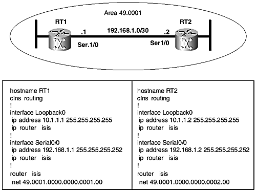
Figure 9-2. IS-IS point-to-point configuration (routers in different areas).
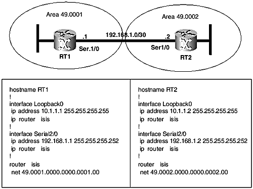
Also shown are relevant excerpts of the IS-IS configurations on the routers. In Figure 9-1, both routers are in the same area and so share a common area prefix (49.0001). Therefore, according to the default IOS behavior, they will establish Level 1 and Level 2 adjacencies. In contrast, however, the routers in Figure 9-2 are in different areas, so they will form only a Level 2 adjacency .
The following commands are useful for verifying proper configuration and operation of IS-IS on Cisco routers:
-
show clns protocol ” Provides a summary of the protocol state on the router(see Example 9-1)
-
show clns neighbors [detail] ” Shows adjacency state information about known neighbors (see Example 9-2)
-
show clns interface ” Shows IS-IS routing information pertaining to an interface (see Example 9-3)
-
show isis topology ” Shows path information for IS-IS nodes in the Level 1 and Level 2 topology (see Example 9-4)
-
show isis database ” Displays known LSPs in the level-1 and level-2 databases(see Example 9-5)
Examples 9-1 through 9-5 show outputs of these commands captured from the routers set up in Figure 9-2. Each example features an output from each router to show the stateof either side of the connection. Because the setup is basic, most of the output is self-explanatory. Some information is provided on the show isis database output in Table 9-1. More information is provided on the other commands in Chapter 10, "Troubleshooting the IS-IS Routing Protocol."
Example 9-1 show clns protocol Output
RT1# show clns protocol IS-IS Router: <Null Tag> System Id: 0000.0000.0001.00 IS-Type: level-1-2 Manual area address(es): 49.0001 Routing for area address(es): 49.0001 Interfaces supported by IS-IS: Loopback0 - IP Serial0/0 - IP Redistributing: static Distance: 110 RRR level: none Generate narrow metrics: level-1-2 Accept narrow metrics: level-1-2 Generate wide metrics: none Accept wide metrics: none RT2# show clns protocol IS-IS Router: <Null Tag> System Id: 0000.0000.0002.00 IS-Type: level-1-2 Manual area address(es): 49.0002 Routing for area address(es): 49.0002 Interfaces supported by IS-IS: Loopback0 - IP Serial0/0 - IP Redistributing: static Distance: 110 RRR level: none Generate narrow metrics: level-1-2 Accept narrow metrics: level-1-2 Generate wide metrics: none Accept wide metrics: none
Example 9-2 show clns neighbors detail Command Output
RT1# show clns neighbors detail System Id Interface SNPA State Holdtime Type Protocol RT2 Se0/0 *HDLC* Up 27 L2 IS-IS Area Address(es): 49.0002 IP Address(es): 192.168.1.2* Uptime: 00:48:46 RT2# show clns neighbors detail System Id Interface SNPA State Holdtime Type Protocol RT1 Se0/0 *HDLC* Up 26 L2 IS-IS Area` Address(es): 49.0001 IP Address(es): 192.168.1.1* Uptime: 00:52:14
Example 9-3 show clns interface Command Output
RT1# show clns interface ser 0/0 Serial0/0 is up, line protocol is up Checksums enabled, MTU 1500, Encapsulation HDLC ERPDUs enabled, min. interval 10 msec. RDPDUs enabled, min. interval 100 msec., Addr Mask enabled Congestion Experienced bit set at 4 packets CLNS fast switching enabled CLNS SSE switching disabled DEC compatibility mode OFF for this interface Next ESH/ISH in 3 seconds Routing Protocol: IS-IS Circuit Type: level-1-2 Interface number 0x0, local circuit ID 0x100 Level-1 Metric: 10, Priority: 64, Circuit ID: RT1.00 Number of active level-1 adjacencies: 0 Level-2 Metric: 10, Priority: 64, Circuit ID: RT1.00 Number of active level-2 adjacencies: 1 Next IS-IS Hello in 8 seconds RT2# show clns interface serial0/0 Serial0/0 is up, line protocol is up Checksums enabled, MTU 1500, Encapsulation HDLC ERPDUs enabled, min. interval 10 msec. RDPDUs enabled, min. interval 100 msec., Addr Mask enabled Congestion Experienced bit set at 4 packets clns fast switching enabled clns SSE switching disabled DEC compatibility mode OFF for this interface Next ESH/ISH in 8 seconds Routing Protocol: IS-IS Circuit Type: level-1-2 Interface number 0x0, local circuit ID 0x100 Level-1 Metric: 10, Priority: 64, Circuit ID: RT2.00 Number of active level-1 adjacencies: 0 Level-2 Metric: 10, Priority: 64, Circuit ID: RT2.00 Number of active level-2 adjacencies: 1 Next IS-IS Hello in 2 seconds
Example 9-4 show isis topology Command Output
RT1# show isis top IS-IS paths to level-1 routers System Id Metric Next-Hop Interface SNPA RT1 -- IS-IS paths to level-2 routers System Id Metric Next-Hop Interface SNPA RT1 -- RT2 10 RT2 Se0/0 *HDLC* RT2# show isis topology IS-IS paths to level-1 routers System Id Metric Next-Hop Interface SNPA RT2 -- IS-IS paths to level-2 routers System Id Metric Next-Hop Interface SNPA RT1 10 RT1 Se0/0 *HDLC* RT2 --
Example 9-5 show isis database Command Output
RT1# show isis database IS-IS Level-1 Link State Database LSPID LSP Seq Num LSP Checksum LSP Holdtime ATT/P/OL RT1.00-00 * 0x00000008 0x8B75 1126 1/0/0 RT1.01-00 * 0x00000001 0x459B 1131 0/0/0 IS-IS Level-2 Link State Database LSPID LSP Seq Num LSP Checksum LSP Holdtime ATT/P/OL RT1.00-00 * 0x0000008A 0x8FED 1126 0/0/0 RT2.00-00 0x0000001E 0xB82C 998 0/0/0 RT2# show isis database IS-IS Level-1 Link State Database LSPID LSP Seq Num LSP Checksum LSP Holdtime ATT/P/OL RT2.00-00 * 0x00000019 0x3DAB 883 1/0/0 RT2.01-00 * 0x0000000D 0x339F 980 0/0/0 IS-IS Level-2 Link State Database LSPID LSP Seq Num LSP Checksum LSP Holdtime ATT/P/OL RT1.00-00 0x0000008A 0x8FED 931 0/0/0 RT2.00-00 * 0x0000001E 0xB82C 808 0/0/0
Table 9-1 describes the fields in the show isis database command output shown in Example 9-5.
Table 9-1. Explanation of the Fields in the show isis database Commands
| Attribute | Comments |
|---|---|
| * | Indicates LSP is originated by the local system. |
| LSPID | LSP identifier. Column lists all known Level 1 and Level 2 LSPs. |
| LSP Seq Number | LSP sequence number for tracking the current version of LSP. |
| LSP Checksum | Checksum calculated at LSP origin. If it changes during storage or flooding, the LSP is corrupted and needs to be purged from the network. |
| LSP Holdtime | Time to expiration of LSP in seconds. |
| ATT | Attached bit. Set in Level 1 LSP by Level 2 routers to help Level 1 interarea traffic. |
| P | Partition bit. Indicates that the router supports partition repair. |
| OL | Overload bit. When set, it indicates resource problems, and the originating router should not be used in transit paths. Can be manually set for administrative reasons in IOS with set-overload-bit command. |
EAN: 2147483647
Pages: 144
- Step 1.1 Install OpenSSH to Replace the Remote Access Protocols with Encrypted Versions
- Step 4.1 Authentication with Public Keys
- Step 4.7 Using Public Key Authentication for Automated File Transfers
- Step 5.2 Troubleshooting Common OpenSSH Errors/Problems
- Step 6.2 Using Port Forwarding Within PuTTY to Read Your E-mail Securely