Essentials of IP Addressing
Addressing and routing are inextricably linked. To provide a datagram (packet) delivery service, IP needs to have an addressing scheme to denote the source of a packet and its intended destination. Having a native addressing scheme enables IP, which operates at Layer 3, to be independent of the underlying LAN or wide-area network (WAN) transport medium. The original architects of the IP protocol chose a 32-bit addressing scheme, which in raw value allows 2 32 (4,294,967,295) unique host addresses to be defined.
Although this number seemed reasonably large at the initial stages of deployment of the Internet, the 32-bit addressing scheme has turned out to be one of the significant shortcomings of IP version 4 (IPv4). This is because of the unexpected large-scale, multinational expansion of the Internet. Various clever schemes, such as Network Address Translation ( NAT ), have been adopted by the Internet community to slow down the pace of depletion of the IPv4 address space. NAT allows translation between the private address space and public space, making it possible for a large number of hosts using private addresses to share a few public addresses on an as-needed basis. Also building momentum and gaining popularity is a new IP addressing scheme referred to as IP version 6 ( IPv6 ). IPv6 provides a larger address space with 128-bit-wide addresses. With an address size four times longer, IPv6 can support a far larger number of addresses than its predecessor, IPv4.
The following subsections discuss various concepts related to IP addressing, including the following:
-
IPv4 address classes
-
Private IPv4 address space
-
IPv4 subnetting and variable subnet masking
-
CIDR
Classful and Classless Addressing
In general, an important aspect of network design involves management of the allocated address space through frugal assignment of groups of addresses of varying sizes. The concept of address classes was introduced into IP networking to assist manageability of the IPv4 address space by carving it into predefined " chunks ." Five address classes (A, B, C, D, and E) were defined and distinguished by the setting of the most significant bits of the most significant byte in the IP address. These settings allowed the address space to be carved into groups or classes of addresses, each of which supported a certain number of hosts. IP networks were then allocated a group of addresses from the various address classes to match their current size and future growth potential. Administrators of these networks were, in turn , supposed to assign addresses to the connected hosts, thus facilitating management of the address space. Three of the five address classes (A, B, and C) delineated the associated 32-bit IP addresses into network identifier (network ID) bits and host identifier (host ID) bits as follows :
-
Class A ” 8-bit network ID, 24-bit host ID
-
Class B ” 16-bit network ID, 16-bit host ID
-
Class C ” 24-bit network ID, 8-bit host ID
Class D addresses were set aside for IP multicast, and Class E addresses were for experimental use. Figure 1-3 illustrates the assignment of bits in Class A addresses.
Figure 1-3. Assignment of Class A address bits.

The dotted-decimal notation used for representing 32-bit binary IP addresses makes them readable by humans . In the dotted-decimal representation, the bits are grouped into octets and separated by dots. Each octet of binary bits is then converted into the decimal equivalent. Table 1-1 shows the address ranges in dotted decimal for all classes. These reflect only host ranges, and network number ranges are implied . Various rules guide the actual address assignment for network devices.
RFC 1700 provides information on reserved addresses and other Internet-related protocol parameters.
Table 1-1. IP Address Classes and Representation
| Address Class | Bit Pattern of First Byte | First Byte Decimal Range | Host Assignment Range in Dotted Decimal |
|---|---|---|---|
| A | 0xxxxxxx | 1 “127 | 1.0.0.1 “ 126.255.255.254 |
| B | 10xxxxxx | 128 “191 | 128.0.0.1 “ 191.255.255.255.254 |
| C | 110xxxxx | 192 “223 | 192.0.0.1 “ 223.255.255.254 |
| D | 1110xxxx | 224 “239 | 224.0.0.1 “ 239.255.255.254 |
| E | 11110xxx | 240 “255 | 240.0.0.1 “ 255.255.255.255 |
The foregoing discussion relates to what is described as classful addressing, so called because of the class-related interpretation of the IP address space. The flip side of classful addressing is classless addressing.
Classless IP addressing abandons the notion of IP address classes by denoting the "would-be" network number of an IP address as some prefix of a specific length. This method of interpreting IP addresses allows for more flexibility in address allocation and contributes to efficient usage of the IPv4 address space. Classless interpretation of IP addresses allows a large address block (Class A, for example) to be split among multiple organizations instead of being allocated to a single organization that doesn't have enough hosts and growth potential for the whole class. In the reverse direction, classless addressing allows multiple Class C addresses to be aggregated into a larger block and advertised as a single address prefix. Address aggregation using CIDR provides great memory-saving opportunities on routers connected to the Internet, which is necessary for scaling routing on the Internet.
Private Address Space
The private address space was originally set aside for IP networks that are not connected to the public Internet. NAT has emerged as one of the innovative ways to conserve IP addresses by converting between public Internet and private addresses. This procedure allows some networks with private addresses to connect to the public Internet. The following three blocks of addresses are reserved for private Internets by RFC 1918:
-
10.0.0.0 “ 10.255.255.255
-
172.16.0.0 “ 172.31.255.255
-
192.168.0.0 “ 192.168.255.255
Subnetting and Variable-Length Subnet Masks
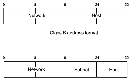
IP address subnetting existed before the introduction of classless addressing and provided a way to split a classful IP network number into multiple smaller address groups that can be applied to different segments of a network. Subnetting introduced another level of hierarchy into the structure of IP address classes, by taking a couple of bits from the host ID field to extend the network ID, creating subnetworks (or simply subnet ). For example, one octet of the two-octet host bits of a Class B address might be used to create 255 subnets, each with only an octet of host bits (see Figure 1-4).
Figure 1-4. Class B subnet example.

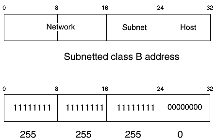
Subnetting an original IP network number into smaller blocks allows efficient assignment of addresses to the smaller segments of a network. An IP subnet mask is used with IP addresses to demarcate the host bits. A subnet mask uses a contiguous string of 1s to represent the network and subnet bits and 0s for the host bits. The subnet mask is also represented in dotted-decimal format. The mask for the subnetted Class B in Figure 1-3 is illustrated in Figure 1-5.
Figure 1-5. Subnet mask example.

As shown in Figure 1-5, the range of subnets for 172.16.0.0, which has an original mask of 255.255.0.0 when subnetted by 8 bits, is 172.16.1.0, 172.16.2.0, 172.16.3.0, ,172.16.255.0, each with a mask of 255.255.255.0.
A common way to represent an IP address and its mask is by specifying the address and just the number of bits in the mask. For example, 172.16.1.0 255.255.255.0 can be represented as 172.16.1.0/24 and 172.16.0.0 255.255.0.0 as 172.16.0.0/16.
VLSM is an abstraction of subnetting that allows different masks to be applied to one network number, providing more flexibility and efficiency in the use of IP addresses. In essence, VLSM uses multiple subnet masks to subnet an address multiple times and into different sizes as needed. For example, you can take 172.16.0.0/16, subnet it to 8 bits, take one of the subnets (172.16.1.0/24), and subnet it further to another 4 bits to obtain smaller blocks, such as 172.16.1.0/28, 172.16.1.16/28, 172.16.1.32/28, and so on.
Classless Interdomain Routing
As discussed in the previous section, VLSM helps improve efficiency of address usage within a network. Yet another problem, which became apparent in the early 1990s, was the imminent depletion of IPv4 addresses because of an inefficient allocation method, which assigned large classful chunks of the IP address space (typically Class B addresses) to not-large-enough organizations. To alleviate this problem, organizations were instead assigned multiple Class C addresses that would meet their immediate needs. As the Internet grew in size, however, routing software and hardware became strained by the growing size of the Internet routing tables because of the many individual Class C entries. The introduction of CIDR allowed the IP network number in addresses to be any length, obsolescing the notion address classes and paving the way for resource-saving (memory and processing cycles) efficient aggregation of routes in the Internet tables. However, eliminating the strict boundaries enforced by IP address classes allowed splitting of classful network addresses, such as Class A network numbers , over multiple network domains.
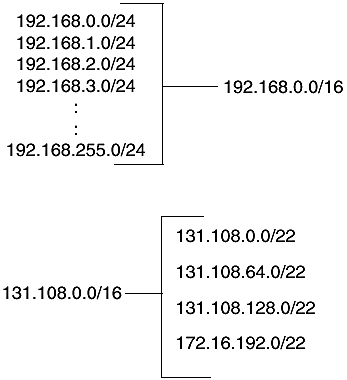
With CIDR, a group of Class C address, such as 192.168.0.0 “ 192.168.255.0, can be aggregated as 192.168.0.0/16 instead of floating in the routing tables as 256 individual Class C addresses. Such an aggregation (192.168.0.0/16) is frequently referred to as a CIDR block or a supernet.
Similarly, CIDR allows an address such as 131.108.0.0/16 to be divided and allocated to four different organizations rather than one, as follows: 131.108.0.0/22, 131.108.64.0/22, 131.108.128.0/22, and 131.108.192.0/22 (see Figure 1-6). See the section, "References," for suggested reading on CIDR.
Figure 1-6. CIDR blocks.

EAN: 2147483647
Pages: 144