Understanding the Coordinate Systems
| [ LiB ] |
Understanding the Coordinate Systems
Many years ago, mathematicians only visualized objects in 3D space by drawing objects on a graph system with a pencil. But today, due to technological innovations, such people have computers that bring the old concepts of mathematics alive . Computers add a new dimension to doing math. People are more comfortable with visual learning, which might be a good thing for children learning math in future years.
Because we live in a 3D world, learning about 3D shouldn't be a problem for our minds to comprehend. There are two major types of representations that programmers use to define their 3D world. A simple sheet of printing paper defines 2D spacethe width of the paper is the X axis and the height is the Y axis. The trick to defining 3D space is adding the third dimension (the Z axis) that completes the definition. If you take a pencil and hold it perpendicular to the paper, the pencil becomes the Z axis. The Z axis can be defined in two ways. A typical 2D coordinate system is defined in the follow-ing format: left (x) to right (+x), and top (+y) to bottom (-y). When adding the Z axis, the positive and negative ends of the axis can point in or out of the paper. There's really no right or wrong way to define the Z axis.
People drive on the left side in England, yet drive on the right side in the United States. Again it's a preferred choice by the programmer who designs the application.
NOTE
TIP
In most computer systems,the rendering libraries and the graphics memory are arranged such that the Y axis is inverted.This may be confusing at first,but you get used to it after a while.Basically,just think of the computer screen as Quadrant I of the Cartesian coor dinate system with the Y axis inverted and (0,0) in the upper-left corner of the screen.
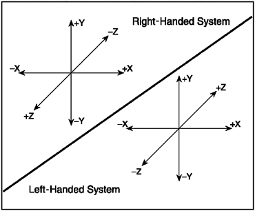
The important distinction when defining the left-oriented system from the right-oriented system is how the points are ordered in defining an object in 3D space. The normal of an object would be flipped based on the direction of the Z axis. This book uses the left-oriented system because it's very common in most modern applications. However, the primitives (Material and Sphere ) in the scene can be defined in both systems. The positive end of the Z axis is going into the screen and the negative end is coming out. Take a look at Figure 8.1 and be sure to remember the distinction.
Figure 8.1. In the left- handed system,the Z axis points into the screen.In the right-handed system, the Z axis points out of the screen.

Local Space/Model Space
Over the many years of research and development, three common spaces have been derived for 3D rendering applications. These spaces were designed to speed up the rendering pipeline of an application for efficiency and optimization. This is because in many applications data is constantly changing and objects need to be structured in a complex format to allocate, delete, and preserve data.
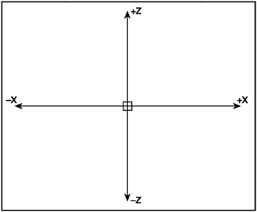
Because some applications such as 3D games change data in real-time, the original definition or the vertices of an object must be preserved in order to transform and preview an object. This requires a space to save the original definition of an object in order to make copies and position them in the scene. Hence, the local coordinate system was derived. The original definition of the object must be in a centered manner whereby the vertices are in unit length. The unit vertices are then scaled and transformed when the object is actually used. The system typically reads in the data from file and loads it into structured memory for later use. The vertices of an object are typically centered at the local origin of (0,0,0). This local origin can be anywhere in space and doesn't need to be located at the world origin of (0,0,0). Remember the local origin is relative so try to think of it as the center of mass (versus the center of volume). See Figure 8.2 for an example of local space . After the object is read in, it is moved into another space for manipulation.
Figure 8.2. Local space is defined where the ver tices of an object are situ ated around the origin of the system (0,0,0).

NOTE
TIP
Many games programming compa nies develop their characters in model space.Sometimes the charac ters are animated in model space as well as assigned textures.
World Space
As the object is in local space it must then be transformed and positioned within the 3D world. This transformation creates a new object that is a translated and rotated version of the original. The object's vertices have been changed to be at some arbitrary position and rotation. A unit cube can be scaled up by 50 times its original size and positioned somewhere in the world. This new space is called world space . World space includes a set of objects originally defined in model space, which are then are transformed, rotated, and translated.
A modeling application typically takes a set of objects that are in local space and transforms them to world space. By rotating and moving objects around the in world space, the geometry of the scene is determined. A composition of stairs, chairs, ceilings, and picture frames on the walls are all applied to an environment. Artists don't only define the geometry of the scene, they also add the lights, apply the materials, map the textures, align the textures, and position the camera to perceive the scene. The next stage is to perceive the world using the eyes of the observer or the camera.
Camera Space
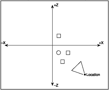
The camera only sees a portion of the scene at a time. The camera moves around the scene and records visible data to the image plane based on its orientation and position. The camera doesn't follow any alignment rules and can change dynamically if needed. The camera is normally rotated at some degree relative to the world axis alignment and also positioned at some location from the world origin (0,0,0). This local camera movement is called the camera space . See Figure 8.3 for an example of camera space. The camera is a special entity because its local coordinate system must be specifically designed to perceive the scene. Because the world is drawn from the camera you need to render objects relative to the camera so that everything moves and rotates opposite to the camera. If the camera moves forward the world moves backwards ; if the camera turns 90 degrees left, the world will adjust in rotation so the scene would be rendered properly.
Figure 8.3. Camera space is based upon the viewer navigating through the scene and then record ing the closest viewable objects that are in the field of view.

In many modern applications, you can get away with using only two spaces for rendering. This is because the model can be read in with the objects already defined in world space. For example, Lightwave 3D comes in mod-eler and renderer forms. An artist develops the mesh using the modeler and then renders the scene with all other assets in the renderer. The applications in this book use two coordinate systems because you're creating a post-process rendering application and not a real-time game. I will not reconstruct or change the mesh during the course of rendering. Games typically use all three spaces to manipulate objects in real-time.
NOTE
TIP
The best way to understand camera space is to pretend you are walking around a room with a camcorder. Whatever shows up in the preview is recorded.This is the camera space.
| [ LiB ] |
EAN: 2147483647
Pages: 128