8.1 From Requirements to Models
8.1 From Requirements to Models
The requirements specification of a system states the goals that the system is expected to satisfy. These are couched in application domain terms, describing the desired behavior of the proposed system in the context of its environment. It is the responsibility of the requirements engineers to elicit the requirements from the system stakeholders and to produce the requirements specification. Even at this stage, models are essential to facilitate understanding and analysis. For instance, the different scenarios that the system should support can be captured as use case models using the Unified Modeling Language (UML). These provide a description of the various actors that interact with the system and the typical interactions. Use case scenarios can also be useful later in examining traces in the design model and test cases in the implemented system. Furthermore, the requirements specification should identify the particular properties of interest. This can help to articulate the safety and progress properties which must hold for the system.
The process of design is required to decompose the requirements into a design architecture. This describes the gross organization and global structure of the system in terms of its constituent components. In order to cope with complexity, hierarchical composition is employed. Quite simply, this means that the architecture is composed from components such that each component may be composite, constructed from simpler components.
The components of a design architecture have a state, exhibit some well-defined behavior, and have a unique identity. The identity distinguishes it from all other components; the behavior represents its outwardly visible and testable activity; and the state of a component represents the cumulative results of its behavior. Design architectures and components satisfy the basic three principles underlying object-oriented approaches:
-
Abstraction – this is the removal or neglecting of unnecessary detail. Levels of abstraction are supported by moving up and down the hierarchy of composed components.
-
Encapsulation – components encapsulate local behavior and information, and only expose activity at their interfaces. Components thereby provide information-hiding facilities.
-
Modularity – the architecture provides an organizing structure of components which dictates the component compositions and interactions.
Any design approach which produces a decomposition into components may be used to provide an outline design architecture. The main activities are as follows:
-
Identify the main actions and interactions of the system.
-
Identify the main components of the system.
-
Structure the components into an architecture.
The aim is to produce an outline architecture that can be used to informally check that all the required system functionality is satisfied. This would include informal checks that the use case scenarios are supported and that the properties of interest are satisfied.
However, in order to check the adequacy and validity of a proposed design in a more rigorous manner, it is necessary to model the system behavior more precisely. A structure diagram model can be used as a precise form of design architecture for a system. Structure diagrams were introduced in Chapter 3 and have been used in subsequent chapters to describe the structure of the models in terms of processes and their interactions. Processes model components and composite processes model composite components. Action hiding, relabeling and sharing are used to model component encapsulation and interaction respectively.
8.1.1 A Cruise Control System
An automobile cruise control system has the following requirements. It is controlled by three buttons: resume, on and off (Figure 8.1). When the engine is running and on is pressed, the cruise control system records the current speed and maintains the car at this speed. When the accelerator, brake or off is pressed, the cruise control system disengages but retains the speed setting. If resume is pressed, the system accelerates or de-accelerates the car back to the previously-recorded speed.

Figure 8.1: Cruise control system.
The hardware that supports the cruise control system is shown in Figure 8.2. It consists of a Parallel Interface Adapter (PIA) which records the actions of the buttons (on, off and resume), the brake (pressed), the accelerator (pressed) and the engine (on or off). The PIA is polled periodically every 100 msec to determine if any of these actions has occurred. A wheel revolution sensor generates interrupts for every wheel revolution in order to enable the system to calculate the current speed of the car. The cruise control system controls the car speed by setting the throttle of the car via a digital-to-analog converter (D/A).
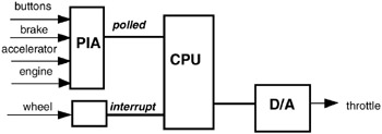
Figure 8.2: Hardware constraints.
8.1.2 Structure of the Model
The structure diagram and actions for the cruise control system shown in Figure 8.3 can be produced using the following design activities:
-
Identify the main actions and interactions of the system.
-
Identify and define the main processes of the system.
-
Identify the main properties of the system.
-
Structure the processes into a structure diagram.
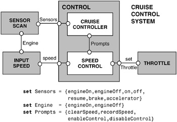
Figure 8.3: Structure diagram for the cruise control system.
These activities correspond to those used in previous chapters and are a refined version of those described above for producing a design architecture. The additional consideration of the properties is to ensure that the model includes those actions necessary for property checking, either as shared actions or actions internal to a process. For instance, we wish to ensure that the cruise control system is disengaged when the brake, accelerator or off button is pressed and that the throttle is eventually set. We discuss these properties later in the chapter.
The main internal control for the cruise control system is provided by two processes: the cruise controller and the speed control. The interface to the external sensors and actuators is provided by the other three processes: sensor scan, input speed and throttle. The cruise controller receives the buttons, brake, accelerator and engine events from the sensor scan. The input speed process monitors the speed when the engine is on and provides the current speed readings to the speed control. Depending on the circumstances, cruise controller triggers clear or record the speed, and enable or disable the speed control. The speed control then sets the throttle accordingly. In this way, the sensor scan encapsulates (information hiding) the periodic process of scanning the sensors, the cruise controller encapsulates the decision as to when speed maintenance is activated, and the speed control encapsulates how to record and maintain speed.
As described in earlier chapters, it is beneficial to model and analyze the system design before embarking on implementation. Parallel composition can be used to compose the system from the model processes according to the composition hierarchy. Animation can be used for scenario checking, and automated model checking can be used for verification of safety and progress properties.
8.1.3 Model Elaboration
Each of the processes is defined in Figure 8.4. The sensors are repeatedly scanned; the input speed is repeatedly monitored when the engine is on; and, when the throttle is set, the car “zooms” off! Speed control is initially disabled. It clears and records the current speed setting, and, when it is enabled, it sets the throttle according to the current speed and the recorded speed. The behavior of the cruise controller is as follows. When the engine is switched on, clearSpeed is triggered and the cruise controller becomes active. When active, pressing the on button triggers recording the current speed and enables the speed control. The system is then cruising. Pressing the on button again triggers recording the new current speed and the system remains cruising. Pressing the off button, brake or accelerator disables the speed control and sets the system to standby. Switching the engine off at any time makes the system inactive.
set Sensors = {engineOn,engineOff,on,off, resume,brake,accelerator} set Engine = {engineOn,engineOff} set Prompts = {clearSpeed,recordSpeed, enableControl,disableControl} SENSORSCAN = ({Sensors} -> SENSORSCAN). INPUTSPEED = (engineOn -> CHECKSPEED), CHECKSPEED = (speed -> CHECKSPEED |engineOff -> INPUTSPEED ). THROTTLE =(setThrottle -> zoom -> THROTTLE). SPEEDCONTROL = DISABLED, DISABLED =({speed,clearSpeed,recordSpeed}->DISABLED | enableControl -> ENABLED ), ENABLED =( speed -> setThrottle -> ENABLED |{recordSpeed,enableControl} -> ENABLED | disableControl -> DISABLED ). set DisableActions = {off,brake,accelerator} CRUISECONTROLLER = INACTIVE, INACTIVE =(engineOn -> clearSpeed -> ACTIVE |DisableActions -> INACTIVE ), ACTIVE =(engineOff -> INACTIVE |on->recordSpeed->enableControl->CRUISING |DisableActions -> ACTIVE ), CRUISING =(engineOff -> INACTIVE |DisableActions->disableControl->STANDBY |on->recordSpeed->enableControl->CRUISING ), STANDBY =(engineOff -> INACTIVE |resume -> enableControl -> CRUISING |on->recordSpeed->enableControl->CRUISING |DisableActions -> STANDBY ). Figure 8.4: Model for the cruise control system.
The corresponding LTS diagram for each of these processes can be inspected to check that the process does indeed model the desired, intuitive behavior. For example, the INPUTSPEED and SPEEDCONTROL LTS diagrams are shown in Figures 8.5 and 8.6 respectively. The LTS diagrams for SPEEDCONTROL and CRUISECONTROLLER are rather complex for easy inspection. At this stage it is often easier to use animation as a means of checking the general process behavior. For instance, the CONTROL subsystem (Figure 8.3) is composed as follows:
||CONTROL =(CRUISECONTROLLER||SPEEDCONTROL).
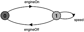
Figure 8.5: LTS diagram for INPUTSPEED.
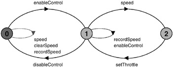
Figure 8.6: LTS diagram for SPEEDCONTROL.
It can be animated to produce answers to the following questions:
-
Is control enabled after the engine is switched on and the on button is pressed?
-
Is control disabled when the brake is then pressed?
-
Is control enabled when resume is then pressed?
The trace depicted on Figure 8.7 confirms this behavior: Note that the trace also illustrates that, when control is enabled, the speed input causes the throttle to be set, and when disabled, it does not. Although various scenarios help to improve our confidence in the adequacy of the model and its behavior, they do not provide an exhaustive check over all possible execution paths. To this end, we need to specify the safety properties of interest.
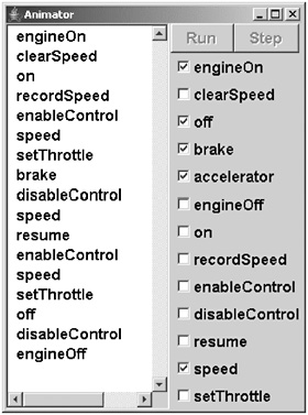
Figure 8.7: CONTROL trace.
8.1.4 Safety Properties
Safety checks are compositional in the sense that, if there is no violation at a subsystem level, then there cannot be a violation when the subsystem is composed with other subsystems. This is because, if the ERROR state of a particular safety property is unreachable in the LTS of the subsystem, it remains unreachable in any subsequent parallel composition which includes the subsystem. Safety checks can therefore be conducted directly on the subsystems which exhibit the behavior to be checked. The following guidelines are used when performing safety checks:
Safety properties should be composed with the appropriate system or subsystem to which the property refers. In order that the property can check the actions in its alphabet, these actions must not be hidden in the system.
A safety property required of the CONTROL subsystem is as follows:
property CRUISESAFETY = ({DisableActions,disableControl} -> CRUISESAFETY |{on,resume} -> SAFETYCHECK ), SAFETYCHECK = ({on,resume} -> SAFETYCHECK |DisableActions -> SAFETYACTION |disableControl -> CRUISESAFETY ), SAFETYACTION =(disableControl->CRUISESAFETY). This property states that, if the CONTROL subsystem is enabled by pressing the on or resume buttons, then pressing the off button, the brake or the accelerator should result in the control system being disabled. The LTS diagram for this property is shown in Figure 8.8. We compose CRUISESAFETY with the CONTROL subsystem processes (Figure 8.3) as follows:
||CONTROL = (CRUISECONTROLLER||SPEEDCONTROL||CRUISESAFETY).
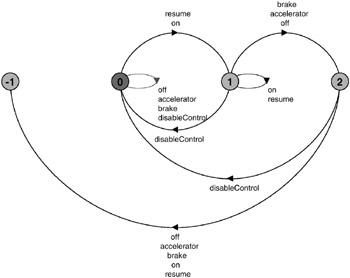
Figure 8.8: LTS diagram for the property CRUISESAFETY.
Safety analysis using LTSA produces the following violation:
Trace to property violation in CRUISESAFETY: engineOn clearSpeed on recordSpeed enableControl engineOff off off
This indicates a violation of the safety property in rather strange circumstances. If the system is enabled by switching the engine on and pressing the on button, and then the engine is switched off, it appears that the control system is not disabled, and disabling actions such as pressing the off button can be performed without the system being disabled. What if the engine were switched on again?
To investigate this, we can animate the control system to produce a trace as follows:
engineOn clearSpeed on recordSpeed enableControl engineOff engineOn speed setThrottle speed setThrottle ...
If the control system remains enabled, then the car will accelerate and zoom off when the engine is switched on again! This is a highly dangerous situation and one that should definitely be avoided.
To further investigate the circumstances which lead to this violation, we can also examine a minimized LTS diagram of the control system, without the safety property and in which only the Sensors and speed actions are visible:
||CONTROLMINIMIZED =(CRUISECONTROLLER||SPEEDCONTROL) @ {Sensors,speed}. Action hiding and minimization help to reduce the size of the diagram and make it easier to interpret. CONTROLMINIMIZED produces the LTS diagram in Figure 8.9 which clearly illustrates the situation where, once the engine is switched on again, the only action which can be performed is speed.
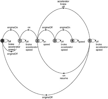
Figure 8.9: Minimized LTS diagram for CONTROLMINIMIZED.
8.1.5 Revising the Model
How can this potentially catastrophic situation be avoided? It is clear that control should be disabled when the engine is switched off. This would ensure that control is not enabled when the engine is switched on again. The required change to the CRUISECONTROLLER is as follows:
... CRUISING =(engineOff -> disableControl -> INACTIVE |DisableActions->disableControl->STANDBY |on->recordSpeed->enableControl->CRUISING ), ...
The CRUISESAFETY safety property did not include a check on the engine status. This must now be included to form an improved safety property:
property IMPROVEDSAFETY = ({DisableActions,disableControl, engineOff} -> IMPROVEDSAFETY |{on,resume} -> SAFETYCHECK ), SAFETYCHECK = ({on,resume} -> SAFETYCHECK |{DisableActions,engineOff} -> SAFETYACTION |disableControl -> IMPROVEDSAFETY ), SAFETYACTION = (disableControl -> IMPROVEDSAFETY). We can now repeat the analysis process as before. This time there are no safety violations. The minimized control system, as shown in Figure 8.10, is clearly reassuring. It indicates that the control system returns to the initial state when the engine is switched off.
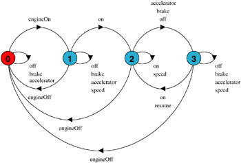
Figure 8.10: Minimized LTS diagram for the revised CONTROLMINIMIZED.
We can now hide internal actions and proceed with the composition of that subsystem to form the complete cruise control system.
||CONTROL = (CRUISECONTROLLER||SPEEDCONTROL||IMPROVEDSAFETY) @ {Sensors,speed,setThrottle}. ||CRUISECONTROLSYSTEM = (CONTROL||SENSORSCAN||INPUTSPEED||THROTTLE). Safety analysis using LTSA verifies that the CRUISECONTROLSYSTEM does not deadlock nor violate the revised safety property.
8.1.6 Progress Properties
Progress checks are not compositional. Even if there is no violation at a subsystem level, there may still be a violation when the subsystem is composed with other subsystems. This is because an action in the subsystem may satisfy progress yet be unreachable when the subsystem is composed with other subsystems which constrain its behavior. Furthermore, action priority acts to discard lower priority action transitions in preference to higher priority ones. With parallel composition, higher priority actions may become unreachable thereby removing particular choices and requiring the restoration of the lower priority actions. We therefore conduct progress checks on the complete target system.
Progress checks should be conducted on the complete target system after satisfactory completion of the safety checks.
We can now subject the cruise control system to progress checks, such as that the throttle is eventually set. In fact, the cruise control system is expected to be capable of operating repeatedly whenever the engine is switched on. Hence, we would expect that no action suffers starvation and that it is always that case that every action can eventually be chosen. We therefore perform a general progress test without specifying particular sets of progress actions. If this general test produces no violations, then we can be certain that there are no violations for any specific progress property. This is the case here, and progress analysis using LTSA on the CRUISECONTROLSYSTEM produces no violations.
However, progress analysis on the original, unrevised CRUISECONTROLSYSTEM, without the safety property, produces the following interesting progress violation:
Progress violation for actions: {accelerator, brake, clearSpeed, disableControl, enableControl, engineOff, engineOn, off, on, recordSpeed, resume} Trace to terminal set of states: engineOn clearSpeed on recordSpeed enableControl engineOff engineOn Cycle in terminal set: speed setThrottle zoom Actions in terminal set: {setThrottle, speed, zoom} The trace confirms the interpretation that control is not disabled when the engine is switched off. Switching the engine on again leads to the terminal set in which the only actions permitted are speed input, the setting of the throttle and the resulting car zoom action. This can be clearly seen in Figure 8.9, except that there the actions setThrottle and zoom are hidden.
Further analysis of the model could be conducted to investigate system behavior under particular adverse conditions. For instance, we could employ action priorities to check progress when sensors are given high priority.
||SENSORSHIGH = CRUISECONTROLSYSTEM << {Sensors}. No progress violations are detected. However, if the sensors are given a low priority:
||SENSORSLOW = CRUISECONTROLSYSTEM >> {Sensors}. then the speed action dominates and, on analysis, we obtain the following violation:
Progress violation for actions: {engineOn, engineOff, on, off, brake, accelerator, resume, setThrottle, zoom} Path to terminal set of states: engineOn tau Actions in terminal set: {speed} This seems to indicate that the system may be sensitive to the priority of the action speed. This can be confirmed since, making speed a high priority is similar to making Sensors low, and making speed a low priority results in the following violation:
Progress violation for actions: {speed, setThrottle, zoom} Path to terminal set of states: Actions in terminal set: {engineOn, engineOff, on, off, brake, accelerator, resume} Thus, models such as this can be used to indicate system sensitivities. If it is possible that erroneous situations detected in the model may occur in the implemented system, then the model should be revised to find a design which ensures that those violations are avoided. However, if it is considered that the real system will not exhibit this behavior, then no further model revisions are necessary. In this way, model interpretation and correspondence to the implementation are important in determining the relevance and adequacy of the model design and its analysis.
In the cruise control system, speed monitoring needs to be carefully controlled so that it neither dominates nor suffers from starvation. If we are confident that this can indeed be achieved in our implementation, then we need perform no further modeling. We now turn our attention to an implementation of the cruise control system, based on the model.
EAN: 2147483647
Pages: 162