Chapter 2: Processes and Threads
In Chapter 1, we noted that in concurrent programs, computational activities are permitted to overlap in time and that the subprogram executions describing these activities proceed concurrently. The execution of a program (or subprogram) is termed a process and the execution of a concurrent program thus consists of multiple processes. In this chapter, we define how processes can be modeled as finite state machines. We then describe how processes can be programmed as threads, the form of process supported by Java.
2.1 Modeling Processes
A process is the execution of a sequential program. The state of a process at any point in time consists of the values of explicit variables, declared by the programmer, and implicit variables such as the program counter and contents of data/address registers. As a process executes, it transforms its state by executing statements. Each statement consists of a sequence of one or more atomic actions that make indivisible state changes. Examples of atomic actions are uninterruptible machine instructions that load and store registers. A more abstract model of a process, which ignores the details of state representation and machine instructions, is simply to consider a process as having a state modified by indivisible or atomic actions. Each action causes a transition from the current state to the next state. The order in which actions are allowed to occur is determined by a transition graph that is an abstract representation of the program. In other words, we can model processes as finite state machines.
Figure 2.1 depicts the state machine for a light switch that has the actions on and off. We use the following diagrammatic conventions. The initial state is always numbered 0 and transitions are always drawn in a clockwise direction. Thus in Figure 2.1, on causes a transition from state(0) to state(1) and off causes a transition from state(1) to state(0). This form of state machine description is known as a Labeled Transition System (LTS), since transitions are labeled with action names. Diagrams of this form can be displayed in the LTS analysis tool, LTSA. Although this representation of a process is finite, the behavior described need not be finite. For example, the state machine of Figure 2.1 allows the following sequence of actions:
on→off→on→off→on→off→ ...
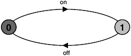
Figure 2.1: Light switch state machine.
The graphical form of state machine description is excellent for simple processes; however, it becomes unmanageable (and unreadable) for large numbers of states and transitions. Consequently, we introduce a simple algebraic notation called FSP (Finite State Processes) to describe process models. Every FSP description has a corresponding state machine (LTS) description. In this chapter, we will introduce the action prefix and choice operators provided by FSP. The full language definition of FSP may be found in Appendix B.
2.1.1 Action Prefix
If x is an action and P a process then the action prefix (x->P) describes a process that initially engages in the action x and then behaves exactly as described by P.
The action prefix operator “->” always has an action on its left and a process on its right. In FSP, identifiers beginning with a lowercase letter denote actions and identifiers beginning with an uppercase letter denote processes. The following example illustrates a process that engages in the action once and then stops:
ONESHOT = (once->STOP).
Figure 2.2 illustrates the equivalent LTS state machine description for ONESHOT. It shows that the action prefix in FSP describes a transition in the corresponding state machine description. STOP is a special predefined process that engages in no further actions, as is clear in Figure 2.2. Process definitions are terminated by “.”.

Figure 2.2: ONESHOT state machine.
Repetitive behavior is described in FSP using recursion. The following FSP process describes the light switch of Figure 2.1:
SWITCH = OFF, OFF = (on ->ON), ON = (off->OFF).
As indicated by the “,” separators, the process definitions for ON and OFF are part of and local to the definition for SWITCH. It should be noted that these local process definitions correspond to states in Figure 2.1. OFF defines state(0) and ON defines state(1). A more succinct definition of SWITCH can be achieved by substituting the definition of ON in the definition of OFF:
SWITCH = OFF, OFF = (on ->(off->OFF)).
Finally, by substituting SWITCH for OFF, since they are defined to be equivalent, and dropping the internal parentheses we get:
SWITCH = (on->off->SWITCH).
These three definitions for SWITCH generate identical state machines (Figure 2.1). The reader can verify this using the LTS analysis tool, LTSA, to draw the state machine that corresponds to each FSP definition. The definitions may also be animated using the LTSA Animator to produce a sequence of actions. Figure 2.3 shows a screen shot of the LTSA Animator window. The animator lets the user control the actions offered by a model to its environment. Those actions that can be chosen for execution are ticked. In Figure 2.3, the previous sequence of actions, shown on the left, has put the SWITCH in a state where only the on action can occur next. We refer to the sequence of actions produced by the execution of a process (or set of processes) as a trace.
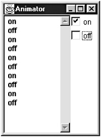
Figure 2.3: LTSA Animator window for SWITCH.
The process TRAFFICLIGHT is defined below with its equivalent state machine representation depicted in Figure 2.4.
TRAFFICLIGHT = (red->orange->green->orange->TRAFFICLIGHT).

Figure 2.4: TRAFFICLIGHT.
In general, processes have many possible execution traces. However, the only possible trace of the execution of TRAFFICLIGHT is:
red→orange→green→orange→red→orange→green ...
To allow a process to describe more than a single execution trace, we introduce the choice operator.
2.1.2 Choice
If x and y are actions then (x->P|y->Q) describes a process which initially engages in either of the actions x or y. After the first action has occurred, the subsequent behavior is described by P if the first action was x and Q if the first action was y.
The following example describes a drinks dispensing machine which dispenses hot coffee if the red button is pressed and iced tea if the blue button is pressed.
DRINKS = (red->coffee->DRINKS |blue->tea->DRINKS ).
Figure 2.5 depicts the graphical state machine description of the drinks dispenser. Choice is represented as a state with more than one outgoing transition. The initial state has two possible outgoing transitions labeled red and blue. Who or what makes the choice as to which action is executed? In this example, the environment makes the choice – someone presses a button. We will see later that a choice may also be made internally within a process. The reader may also question at this point if there is a distinction between input and output actions. In fact, there is no semantic difference between an input action and an output action in the models we use. However, input actions are usually distinguished by forming part of a choice offered to the environment while outputs offer no choice. In the example, red and blue model input actions and coffee and tea model output actions. Possible traces of DRINKS include:
red→coffee→red→coffee→red→coffee...... blue→tea→blue→tea→blue→tea...... blue→tea→red→coffee→blue→tea→blue→tea......
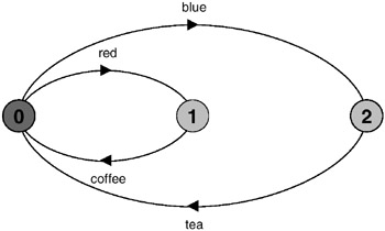
Figure 2.5: DRINKS state machine.
As before, the LTSA Animator can be used to animate the model and produce a trace, as indicated in Figure 2.6. In this case, both red and blue actions are ticked as both are offered for selection.
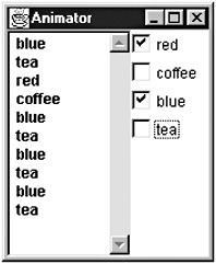
Figure 2.6: LTSA Animator window for DRINKS.
A state may have more than two outgoing transitions; hence the choice operator “|” can express a choice of more than two actions. For example, the following process describes a machine that has four colored buttons only one of which produces an output.
FAULTY = (red ->FAULTY |blue ->FAULTY |green->FAULTY |yellow->candy->FAULTY ).
The order of elements in the choice has no significance. The FAULTY process may be expressed more succinctly using a set of action labels. The set is interpreted as being a choice of one of its members. Both definitions of FAULTY generate exactly the same state machine graph as depicted in Figure 2.7. Note that red, blue and green label the same transition back to state(0).
FAULTY = ({red,blue,green}-> FAULTY |yellow -> candy -> FAULTY ). 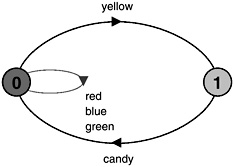
Figure 2.7: FAULTY.
Non-Deterministic Choice
The process (x->P|x->Q) is said to be non-deterministic since after the action x, it may behave as either P or Q. The COIN process defined below and drawn as a state machine in Figure 2.8 is an example of a non-deterministic process.
COIN = (toss -> heads -> COIN |toss -> tails -> COIN ).
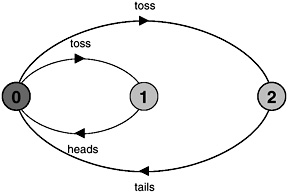
Figure 2.8: COIN.
After a toss action, the next action may be either heads or tails. Figure 2.9 gives a sample trace for the COIN process.

Figure 2.9: LTSA Animator window for COIN.
2.1.3 Indexed Processes and Actions
In order to model processes and actions that can take multiple values, both local processes and action labels may be indexed in FSP. This greatly increases the expressive power of the notation. Indices always have a finite range of values that they can take. This ensures that the models we describe in FSP are finite and thus potentially mechanically analyzable. The process below is a buffer that can contain a single value – a single-slot buffer. It inputs a value in the range 0 to 3 and then outputs that value.
BUFF = (in[i:0..3]->out[i]-> BUFF).
The above process has an exactly equivalent definition in which the choice between input values is stated explicitly. The state machine for both of these definitions is depicted in Figure 2.10. Note that each index is translated into a dot notation “.” for the transition label, so that in[0] becomes in.0, and so on.
BUFF = (in[0]->out[0]->BUFF |in[1]->out[1]->BUFF |in[2]->out[2]->BUFF |in[3]->out[3]->BUFF ).
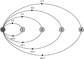
Figure 2.10: BUFF.
Another equivalent definition, which uses an indexed local process, is shown below. Since this uses two index variables with the same range, we declare a range type.
range T = 0..3 BUFF = (in[i:T]->STORE[i]), STORE[i:T] = (out[i] ->BUFF).
The scope of a process index variable is the process definition. The scope of an action label index is the choice element in which it occurs. Consequently, the two definitions of the index variable i in BUFF above do not conflict. Both processes and action labels may have more than one index. The next example illustrates this for a process which inputs two values, a and b, and outputs their sum. Note that the usual arithmetic operations are supported on index variables.
const N = 1 range T = 0..N range R = 0..2*N SUM = (in[a:T][b:T]->TOTAL[a+b]), TOTAL[s:R] = (out[s]->SUM).
We have chosen a small value for the constant N in the definition of SUM to ensure that the graphic representation of Figure 2.11 remains readable. The reader should generate the SUM state machine for larger values of N to see the limitation of graphic representation.
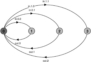
Figure 2.11: SUM.
2.1.4 Process Parameters
Processes may be parameterized so that they may be described in a general form and modeled for a particular parameter value. For instance, the single-slot buffer described in section 2.1.3 and illustrated in Figure 2.10 can be described as a parameterized process for values in the range 0 to N as follows:
BUFF(N=3) = (in[i:0..N]->out[i]-> BUFF).
Parameters must be given a default value and must start with an uppercase letter. The scope of the parameter is the process definition. Alternatively, N may be given a fixed, constant value. This may be more appropriate if N is to be used in more than one process description.
const N = 3 BUFF = (in[i:0..N]->out[i]-> BUFF).
2.1.5 Guarded Actions
It is often useful to define particular actions as conditional, depending on the current state of the machine. We use Boolean guards to indicate that a particular action can only be selected if its guard is satisfied.
The choice (when B x ->P|y ->Q) means that when the guard B is true then the actions x and y are both eligible to be chosen, otherwise if B is false then the action x cannot be chosen.
The example below (with its state machine depicted in Figure 2.12) is a process that encapsulates a count variable. The count can be increased by inc operations and decreased by dec operations. The count is not allowed to exceed N or be less than zero.
COUNT (N=3) = COUNT[0], COUNT[i:0..N] = (when(i<N) inc->COUNT[i+1] |when(i>0) dec->COUNT[i-1] ).

Figure 2.12: COUNT.
FSP supports only integer expressions; consequently, the value zero is used to represent false and any non-zero value represents true. Expression syntax is the same as C, C++ and Java.
In section 2.2, which describes how processes can be implemented in Java, we outline the implementation of a countdown timer. The timer, once started, outputs a tick sound each time it decrements the count and a beep when it reaches zero. At any point, the countdown may be aborted by a stop action. The model for the countdown timer is depicted below; the state machine is in Figure 2.13.
COUNTDOWN (N=3) = (start-> COUNTDOWN[N]), COUNTDOWN[i:0..N] = (when(i>0) tick-> COUNTDOWN[i-1] |when(i==0) beep-> STOP |stop-> STOP ).
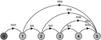
Figure 2.13: COUNTDOWN.
The set of possible traces of COUNTDOWN are as given below.
start→stop start→tick→stop start→tick→tick→stop start→tick→tick→tick→stop start→tick→tick→tick→beep
(Note that the LTSA Animator reports the STOP state as DEADLOCK. Deadlock is a more general situation where a system of processes can engage in no further actions. It is discussed later, in Chapter 6.)
2.1.6 Process Alphabets
The alphabet of a process is the set of actions in which it can engage.
For example, the alphabet of the COUNTDOWN process of the previous section is {start, stop, tick, beep}. A process may only engage in the actions in its alphabet; however, it may have actions in its alphabet in which it never engages. For example, a process that writes to a store location may potentially write any 32-bit value to that location; however, it will usually write a more restricted set of values. In FSP, the alphabet of a process is determined implicitly by the set of actions referenced in its definition. We will see later in the book that it is important to be precise about the alphabet of a process.
How do we deal with the situation described above in which the set of actions in the alphabet is larger than the set of actions referenced in its definition? The answer is to use the alphabet extension construct provided by FSP. The process WRITER defined below uses the actions write[1] and write[3] in its definition but defines an alphabet extension “+{...}” of the actions write[0..3]. The alphabet of a process is the union of its implicit alphabet and any extension specified. Consequently, the alphabet of WRITER is write[0..3].
WRITER = (write[1]->write[3]->WRITER) +{write[0..3]}. It should be noted that where a process is defined using one or more local process definitions, the alphabet of each local process is exactly the same as that of the enclosing process. The alphabet of the enclosing process is simply the union of the set of actions referenced in all local definitions together with any explicitly specified alphabet extension.
EAN: 2147483647
Pages: 162