4.4 Execute (develop the logical design)
|
| < Day Day Up > |
|
4.4 Execute (develop the logical design)
Once we have a good handle on the solution requirements we can begin to develop the logical design.
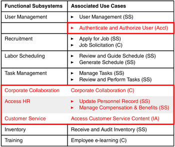
Step 2A - Derive initial AOD
As before, we start by defining the functional subsystems that we will use to seed the initial Architecture Overview Diagram (subsystem). It may be the case that this initial AOD is derived directly from the matched large reusable asset. When such a work product isn't available as part of the matched large reusable asset, you can derive the functional subsystems by grouping the use cases based on related business patterns and common data or processing.
| Functional Subsystems | Associated Use Cases |
|---|---|
| User Management |
|
| Recruitment |
|
| Labor Scheduling |
|
| Task Management |
|
| Corporate Collaboration | Corporate Collaboration (C) |
| Access HR |
|
| Customer Service | Access Customer Service Content (IA) |
| Inventory | Receive and Audit Inventory (SS) |
| Training | Employee e-learning (C) |
From here we can draw an initial AOD (subsystem), highlighting the major business functions and their interconnections.
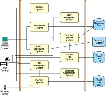
Figure 4-4: IFBs architecture overview diagram (subsystem)
Step 2B - Seed the AOD with large reusable assets
Given the AOD (subsystem), it is once again possible to show the mapping (coverage) of the matched large reusable asset.

Figure 4-5: AOD (subsystem) highlighting the coverage of the Portal composite pattern
This same information is shown in Table 4-4.
|
|
Since the matched large reusable asset is the Portal composite pattern, as a final step in validating the coverage we can look at the Application patterns associated with the "covered" functionality to be sure it is consistent with the PCP. [2]
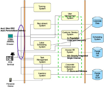
Figure 4-6: Validating Application patterns for function subsystems included within the PCP
Step 2C - Identify and apply patterns for each AOD delta requirement
Next, the delta requirements must be addressed—first identifying the core business and/or integration patterns involved for each requirement, and then identifying the specific Application patterns.
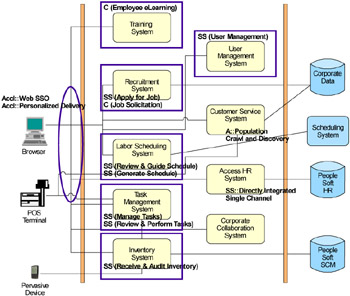
Figure 4-7: Business and Integration patterns for delta requirements
Table 4-5 describes the Application pattern selection for each of the delta requirements.
| e-Learning System | C::Managed Collaboration—Due to workflow directed collaboration. |
| Job Solicitation | C::Store and Retrieve—Simple document publishing |
| Apply for Job |
|
| Review and Guide Schedule |
|
| Generate Schedule | SS::Directly Integrated Single Channel—Single delivery channel and monolithic application |
| Manage Tasks | SS::Directly Integrated Single Channel—Single delivery channel and monolithic application |
| Review and Perform Tasks |
|
| Receive and Audit Inventory |
|
| User Management | SS::Directly Integrated Single Channel—Single delivery channel and monolithic application |
Finally, these Application patterns can be shown in the AOD (Figure 4-8 on page 185).
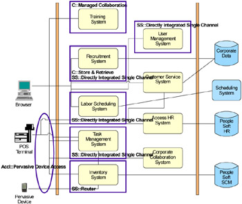
Figure 4-8: Application patterns shown in the AOD
4.4.1 Transition to AOD (logical nodes)
Step 2D - Transition the AOD from subsystem view to logical node view
The next step is to drive down to the runtime pattern level for the solution. Once again, we have seeded the biggest chunk of the AOD (logical nodes) from the corresponding work product of the matched large reusable asset. Figure 4-9 on page 186 shows a slightly customized PCP runtime pattern used to seed the AOD (logical nodes).
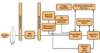
Figure 4-9: AOD (logical nodes) seeded from the customized PCP runtime pattern
Once the initial AOD (logical nodes) is established, each of the delta application patterns can have their individual runtime patterns analyzed to determine how to integrate it within the developing solution. Figure 4-10 on page 187 illustrates adding the wireless gateway node to the AOD and overlaying the AccI::Pervasive Device Access runtime pattern.
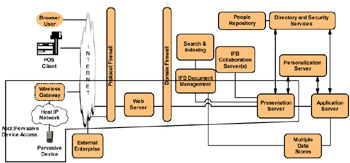
Figure 4-10: Adding Pervasive Device Access support
Figure 4-11 demonstrates adding an integration server to support the runtime for the SS::Router application pattern.
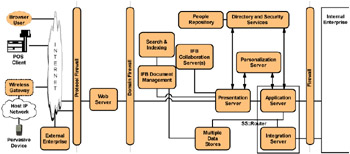
Figure 4-11: Adding integration server support
Figure 4-12 on page 188 represents the complete runtime.
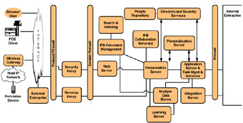
Figure 4-12: Final AOD (logical nodes) for IFB
Table 4-6 depicts the additional decisions made in coming up with the final AOD shown in Figure 4-12.
| Functional or Non-Functional requirement | Architecture Decision (supporting logical nodes)) |
|---|---|
| eLearning System | Supported with Learning Server node |
| Inventory System (multiple delivery channels) | Supported with Integration Server node |
| NFR—Security | Moved Web server to internal network and added Security proxy node |
| Presentation server access to external content | Supported with Reverse proxy node in DMZ |
Step 2F - Conduct technical walkthroughs to ensure that functional requirements are met
Here we validate the completeness of the logical solution by walking through each use case. Table 4-7 on page 189 provides the steps for the Update Personnel Record use case. The paths associated with each step are highlighted on Figure 4-13 on page 189. Note that this specific walkthrough highlights the fact that there should be direct connections between both the presentation and collaboration servers and the internal enterprise (PeopleSoft HR system).
| Step | Description | Comments on Diagram |
|---|---|---|
| 1 | An Associate enters People Management Solutions via the Dynamic Workplaces™ Portal | Standard login and navigation from a browser client to the ODW. |
| 2 | The Associate reviews his or her personnel information | The presentation server utilizes a connector to the HR system providing the key data items (appropriately filtered for a specific Associate) on the ODW desktop. |
| 3 | The Associate chooses to update his or her address | |
| 4 | A notification is posted to the Operational Manager and the HR system | The same connector interface permits updates to specific fields, again based on role and specific user (standard notification behavior of HR system for data field updates). |
| 5 | The HR system posts an update notification to the Associate | Standard notification behavior of HR system for data field updates |
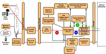
Figure 4-13: Walkthrough for the Update Personnel Records use case
[2]Portal composite pattern
|
| < Day Day Up > |
|
EAN: 2147483647
Pages: 82