Placing IDS Sensors
Classical intrusion detection systems operate at the network and host levels. With regard to host-level intrusion detection systems, the answer to the question of where to put the IDS sensors is easy, since they must reside on the most important network hosts (database servers, web servers, and so on). The issue that interests us, therefore, is the problem of correctly placing IDS network sensors. This topic will be covered in detail in this section.
As a rule, network sensors of an intrusion detection system are installed on the following network locations:
-
Between a router and firewall
-
In the "demilitarized zone" (DMZ)
-
Behind a firewall
-
Near a remote access server or near a modem pool
-
On the network backbone
-
Within key segments of an internal network
-
In remote offices
The Network Sensor between the Router and Firewall
Protecting corporate networks against external attacks is one of the most important functions of IDS network sensors. This task determines the first way to install the network sensor - between the router and firewall (Fig. 10.1). This type of installation will allow you to control all traffic in the corporate network (including the traffic passing through the demilitarized zone), as well as all outbound traffic, which is not locked by a firewall. This solution also allows you to protect the firewall, which quite often also becomes a target of external attacks. However, this position does not allow the network sensor to control the traffic that is isolated by the firewall and router, circulating within the LAN and the demilitarized zone, and outbound from the DMZ into the local area network. Furthermore, bear in mind that the traffic coming into the network through a point that is not controlled by the network sensor (for example, via a backup connection or modem) will not be analyzed, and consequently, attacks present in such traffic will not be detected.
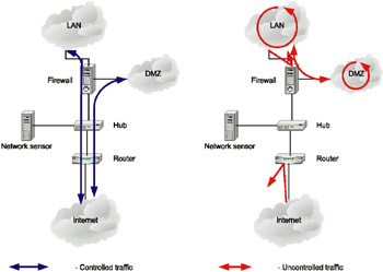
Fig. 10.1. Placing the network sensor between the router and firewall
In this case, the network sensor is absolutely unprotected, since it is located outside the area protected by the firewall. To secure the sensor, it is recommended that the user take the following measures:
-
Enable Stealth mode
-
Change the default port numbers of the ports used in communications between the sensor and management console
-
Make sure that the network interface responsible for accepting the commands from the management console and transmitting information on registered events back to it is connected to the internal network or to a separate interface of the firewall
-
Use non-routable addresses (RFC 1918) for the management interface
The Network Sensor in the Demilitarized Zone
Another important function of network sensors (Fig. 10.2) is their role in protecting devices located in the demilitarized zone (DMZ). The list of such devices includes Web, FTP and SMTP servers, an external DNS server, and other hosts that must be accessible to external users. Obviously, the IDS network sensor does not analyze traffic that does not pass through a controlled zone. I should point out that this solution is not common, because financial resources assigned for purchasing IDSs are usually rather limited. As a rule, most clients prefer to invest in a network sensor installed behind the firewall or between the firewall and router. However, placing the IDS network sensor in the demilitarized zone is justified for companies that actively use external Internet resources (e-shops, Internet portals, etc.)
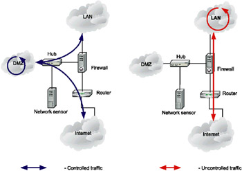
Fig. 10.2. The network sensor in the demilitarized zone
The Network Sensor behind the Firewall
The network sensor is usually placed behind the firewall (on the side of the LAN), as shown in Fig. 10.3, and the first approach that we have discussed is also employed. In this case, it is possible to track the changes in the firewall's operation and to view all traffic passing via the firewall. The network sensor in this configuration lets the administrator make sure that the firewall is correctly configured and that no one can penetrate it in attempts to enter the corporate network. This means that the network sensor controls the firewall configuration and efficiency of its operation. Simultaneous logging of the same events on both sensors (behind and beyond the firewall) enables you to compare the number of attacks detected on both sides of the firewall, thus allowing the detection of problems with the security rules that the administrator created.
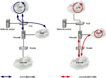
Fig. 10.3. Placing the network sensor behind the firewall
This configuration enables the administrator to control all inbound and outbound traffic in the demilitarized zone, as well as traffic circulating within the LAN segment adjacent to the Internet gateway. The network sensor does not analyze external traffic locked by the firewall or inbound traffic directed to devices located in the demilitarized zone. The approach is even rarer than the previous one, since in this case the firewall is not protected from external attacks. Furthermore, such a configuration does not allow you to trace attacks thwarted by the firewall (for example, port scanning), which could serve as evidence of an intruder's attempts to investigate the company's security system. Early detection of such attempts can help security personnel to take all the required preventive measures in a timely manner.
Network Sensors in Key Segments of the Protected LAN
The most common type of configuration can be seen when network sensors are located within the key segments of an internal network connecting valuable resources or critical applications (such as ERP and CRM). As I mentioned earlier, the most significant damages are usually caused by attacks originating from within. To prevent such losses, be sure to place network sensors within the most critical network segments.
The Network Sensor Near the Remote Access Server
In most companies, the remote access server provides access to corporate resources. When network sensors are located near remote access servers, they are able to control attacks initiated by users accessing the corporate network via those servers (Fig. 10.4).
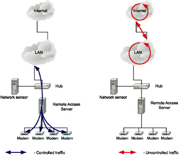
Fig. 10.4. The Network sensor placed near the remote access server
This method is used quite rarely, since it allows administrators to detect only those unauthorized activities initiated by a limited range of users (those who log on to the network using modem connections). All other intruders are not even noticed.
The Network Sensor on the Backbone
Network intrusion detection systems can not efficiently function on most backbones since they are based on different networking principles. ATM, Frame Relay, X.25, and others are modern technologies for building Wide Area Networks (WAN), including backbones that have no relation to multiple access data communication networks.
If Gigabit Ethernet is used as the backbone technology, the situation improves somewhat, but only in a rather insignificant way. Another problem immediately arises. On the backbones, network traffic is rather fast, and the transmission rate significantly exceeds the capabilities of most intrusion detection systems. There are not many sensors that support Gigabit backbones, despite the fact that practically all leaders in this market have declared that their products support Gigabit Ethernet. Some of these products are listed below:
-
RealSecure Gigabit Sensor from Internet Security Systems
-
Cisco IDS 4250 from Cisco Systems
-
NFR NID-320S or 320D from NFR
-
Dragon Sensor Appliance from Enterasys Networks
-
SecureNet 7000 from Intrusion.com
-
ManHunt from Recourse Technologies, purchased by Symantec on July 2002
If you can not afford to purchase gigabit sensors, I would recommend that you use load balancing devices, which will be covered later in this chapter.
Network Sensors in Remote Offices
Placing network sensors in remote offices and affiliates is yet another approach to building an IDS infrastructure. This configuration does not have any specific features, since in this case the network sensor is installed either before or after the firewall, or in the demilitarized zone (if there is one). One important aspect you should remember is that the data exchange between the console and sensors usually takes place via public communication channels. Consequently, you will need to protect all the traffic. Besides this, the amount of data transmitted between remote sensors and the management console can exceed all possible limits.
The recommendations provided here concern the standard placement of IDS network sensors. The particular configuration of the IDS infrastructure depends on the corporate network configuration and on the security policy adopted in the organization.
Using Load Balancing Devices
Load balancing devices let you distribute network traffic to several devices (firewalls, servers, traffic analyzers, etc.) and process it at the same time. Such devices can be both applied to intrusion detection in backbones and used for several other purposes that will be covered later.
TopLayer Networks supplies one of the most popular solutions of this type. It allows the administrator to organize parallel processing of Gigabit Ethernet traffic by several network sensors (Fig. 10.5).
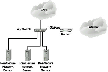
Fig. 10.5. The solution developed by TopLayer and Internet Security Systems
According to Internet Security Systems and Top Layer Networks' test results, the AS3502 AppSwitch device can support up to 9 network sensors. This provides the capability of tracing all network traffic, depending on the gigabit channel's workload [ISS10-00]. Later, this solution was transformed into IDS Balancer (http://www.toplayer.com/Products/ids_balancer.html), providing significant advantages, including the ability to aggregate the traffic from several network segments or even the VLAN, and transmit it to a group of network sensors. At the time of this writing, two IDS Balancer models were available - AS3531 (12 100-Mbit ports) and AS3532 (12 100-Mbit and 2 Gbit ports). Test results for AS3502 are shown in Fig. 10.6 and in Table 10.1.
| Workload | Intrusion detection (%) | |||||||||
|---|---|---|---|---|---|---|---|---|---|---|
| | ||||||||||
| Mbit | % | 1 sensor | 2 sensor | 3 sensor | 4 sensor | 5 sensor | 6 sensor | 7 sensor | 8 sensor | 9 sensor |
| 100 | 10 | 96% | 100% | 100% | 100% | 100% | 100% | 100% | 100% | 100% |
| 200 | 20 | 44% | 88% | 100% | 100% | 100% | 100% | 100% | 100% | 100% |
| 300 | 30 | 32% | 49% | 100% | 100% | 100% | 100% | 100% | 100% | 100% |
| 400 | 40 | 21% | 36% | 60% | 99% | 100% | 100% | 100% | 100% | 100% |
| 500 | 50 | 14% | 39% | 44% | 71% | 94% | 100% | 100% | 100% | 100% |
| 600 | 60 | 14% | 21% | 42% | 64% | 69% | 92% | 100% | 100% | 100% |
| 700 | 70 | 10% | 19% | 32% | 56% | 61% | 85% | 89% | 99% | 100% |
| 800 | 80 | 11% | 14% | 29% | 38% | 60% | 61% | 90% | 93% | 100% |
| 900 | 90 | n/a | n/a | n/a | n/a | n/a | n/a | n/a | n/a | n/a |
| 1000 | 100 | n/a | n/a | n/a | n/a | n/a | n/a | n/a | n/a | n/a |
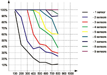
Fig. 10.6. The results of AS3502 AppSwitch testing
The main advantage of IDS Balancer is that additionally, it can send the same traffic to different groups of sensors and even to different groups of devices. For example, incoming data can be redirected to:
-
Sensors responsible for detecting Denial of Service attacks
-
Sensors responsible for detecting HTTP attacks
-
Protocol analyzers
A similar approach - i.e., parallel processing of the fast traffic by distributing it between several analyzers (including IDS network sensors) - is also suggested by NetOptics (http://www.netoptics.com) and several other manufacturers of load-balancing devices. However, you should take into account that such devices might be based on two different load balancing principles - packet-by-packet balancing and flow balancing. Only devices based on the second principle are suitable for using with network intrusion detection systems. For example, IDS Balancer "understands" the traffic of the whole session received from different ports (for example, from different splitters), which allows it to be processed and sent to the sensor so as to let the sensor view the bidirectional interaction as a whole.
These same devices can be used to improve the reliability of the IDS network infrastructure. Connecting a group of sensors to such a load balancing device eliminates any risk of failure. If one of the sensors fails, the device will stop redirecting traffic to it and switch to one of the other sensors of the group. Therefore, you will have to ensure some redundancy when planning the number of sensors to be connected to the balancer. Thus, the failure of a single sensor will not cause other sensors to be overloaded with excessive traffic. To calculate the required number of sensors, use the following formula [Edwards1-02]:
Sensor number = ( (connections number * network speed * duplex coefficient) / IDS performance) + redundancy factor
The duplex coefficient can take a value of 1 or 2, depending on the controlled connection type - half-duplex or full-duplex. If the controlled connection is full-duplex, the amount of traffic increases twofold, and the coefficient takes a value of 2. In most cases, the redundancy factor (an integer) is equal to 1.
For example, to control 4 half-duplex Fast Ethernet connections (from splitters, for example) with a network workload factor of 0.8 (80 Mbit/sec), you must use 5 network sensors providing a performance of up to 90 Mbit/sec:
((4 * 80 * 1) / 90) + 1 = 4.56
If we neglect the redundancy factor by assuming that it is equal to zero, then 4 sensors will be sufficient. In cases when the IDS is overloaded and fails to thwart all attacks (some solutions, such as RealSecure Network Sensor, notify the administrator if such a situation arises), it is possible to connect additional sensors to the load balancing device. Thus, scaling becomes rather easy.
Specific Cases
In recent years, most companies have begun to pay special attention to the matter of having network elements in reserve, since networks perform business-critical tasks. A network infrastructure failure results in financial damages and loss of morale and customer confidence, among other things. There have been several documented cases of bankruptcy that were caused by network failures.
| A Case of Bankruptcy Caused by Network Failure | In January of 2002, intruders attacked CloudNine Communications, one of the most widely known British Internet Service Providers. It became a victim of Distributed Denial of Service (DDoS) attacks, which had already gained some notoriety. DDoS attacks are different from DoS attacks in that the traffic intended to overload the ISP equipment originates from hundreds or even thousands of Internet hosts. CloudNine, a company with 6 years of experience in this segment of the market, was forced to close down and sell the clients' database to its competitor - Zetnet. |
Besides backing up the network equipment, there are two other popular methods of improving network reliability. These methods significantly affect the selection of positions for IDS network sensors:
-
Connecting to the Internet via two different ISPs
-
Usage of asymmetric routes
Till recently, these cases were quite rare in real-world practice. Currently, however, more and more companies are using such methods of improving their networks' reliability. As a result, I'd like to cover such solutions in more detail.
Quite recently, Cisco announced a new set of functions for its IOS operating system - Globally Resilient Internet Protocol (GRIP). These functions provide for automatic network recovery in case of failures (http://www.cisco.com/warp/public/732/Tech/grip/). The most important functions of GRIP include Nonstop Forwarding, Stateful Switchover, and Gateway Load Balancing Protocol. Considering that Cisco network equipment is widely used all over the world, we can assume that this technology will quickly find supporters, and security specialists will have to consider it when selecting positions for IDS components. However, I would like to draw attention to the fact that the methods described in the following few sections are also applicable to networks using GRIP.
Connecting to Multiple Internet Service Providers
Creating a backup channel for Internet connection and automatically switching between channels can be implemented in different ways - both by using the settings of routing protocols (BGP, for example), and with the help of special equipment (such as LinkProof from Radware company). In this case, one can use the simplest approach - install the sensors at any Internet connection point. However, this solution is rather expensive, and not all organizations can afford it. Using load balancing devices, which allows the traffic from several channels to be merged and redirected to a sensor or group of sensors, is an efficient way around this issue (Fig. 10.7).
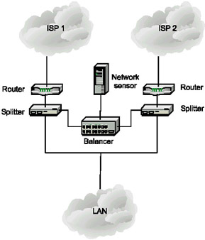
Fig. 10.7. Intrusion detection when using backup Internet connections
A similar scheme can be used for protecting e-commerce hosts (Fig. 10.8). The only difference lies in the presence of multiple lines of defense when applying load balancing devices:
-
The first line of defense is responsible for external traffic coming into the firewalls from the Internet.
-
The second line of defense is responsible for control over the demilitarized zone (a web server of an e-shop or Internet bank).
-
The third line of defense controls the internal network.
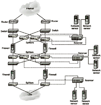
Fig. 10.8. Intrusion detection on e-commerce hosts
Using Asymmetric Routes
In asymmetric networks, omnidirectional traffic goes by different routes. This causes several problems for intrusion detection systems, which can not get complete information on the network interaction in such a case. This might result in false positive or false negative problems. As shown in Fig. 10.9, packets leaving the LAN might follow any of four possible routes. Because of this, installing a network sensor on one of the channels or activating the router's built-in intrusion detection system (when using Cisco routers) produces no effect. Like the previously described case, the situation can be corrected by using load balancing devices.
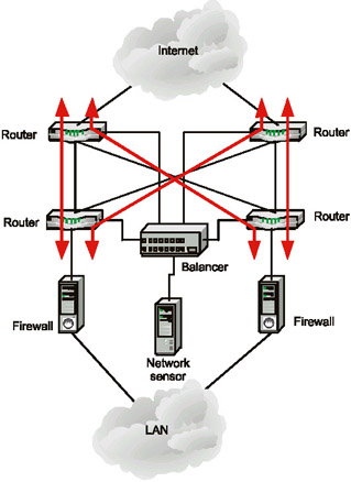
Fig. 10.9. Intrusion detection in asymmetric networks
EAN: 2147483647
Pages: 152