Preparation Work in Visio
|
We'll look at how to create new stereotypes specific to .NET Remoting in Visio. However, before creating the stereotypes, we have some preparation work to do in Visio. The preparation work includes creating a UML solution and adding an Implementation Model (see the box below for detailed explanation) to the solution. The Implementation Model folder will serve as the place for storing UML artifacts we'll create in the remaining parts of this chapter.
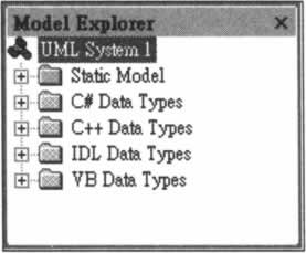
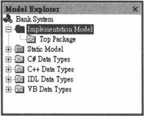
When Visio starts, you have the option of choosing the drawing type for your new drawing. In our case, we'll choose the Software category and UML Model Diagram as the drawing type for our new drawing. Alternatively, you can choose a drawing type by clicking on the menu item File | New | Choose Drawing Type.... After making the choice of a drawing type, you'll see the shape stencils specific to that drawing type. In our case, we'll see stencils for various kinds of UML diagrams. In addition, we'll also see the Model Explorer that organizes your UML artifacts in tree structures. If you don't see the Model Explorer on the screen, you can bring it up by clicking on the menu item UML | View | Model Explorer. The Model Explorer on your screen should look like the one shown overleaf. The root of the tree in the Model Explorer represents the system we're modeling. We'll change its name from UML System 1 to Bank System. To make the name change, right-click on the root node, choose Rename in the pop-up menu, and then type in the new name. Under the root node are folders that represent models or that contain data types of the system. In our screen snapshot above, we see a Static Model folder that represents one model of the Bank System. We also see four data type folders that contain different kinds of data types. Here we'll add a new model to the Bank system. To add a model folder, right-click on the Bank System root node, choose Models in the pop-up menu, and you'll see that the UML Models window pops up. In the UML Models window, there is already an entry for Static Model. To add an entry for our new model, click on the New button, or the blank row below the entry for Static Model and type in Implementation Model in the Model column as the name of our new model. Click the OK button to confirm the changes you've made. Now you should see the Implementation Model folder in the Model Explorer. This folder will be the place where we store the component diagrams, deployment diagrams, component shapes, node shapes, etc, of the Bank System. By now, your Model Explorer should look like the one shown below. Visio will automatically create a Top Package under the Implementation Model folder for you.
| |||||||||||||||||||||||||||||||||||

EAN: N/A
Pages: 85