Architecture Documentation
|
Architecting an application is probably one of the more interesting stages of building an application. In many cases, you're starting with a clean whiteboard with a bunch of ideas about how best to pull off the requirements you've identified earlier in the project. This stage is also one of the riskiest. The decisions made at this stage of a project are very costly to reverse once coding has started. Obviously, good requirements and a good understanding of those requirements are crucial to architecting a good application. In this section of the chapter, we'll review the most common UML diagrams used in the Architecture stage and how they get used. We'll also review the longer-term implications of building good diagrams from a documentation standpoint since that's one of the themes of the entire chapter. Although every designer and developer has a different style, there are a few common diagrams that we can predict to be used at this stage. These include the class diagram and activity diagram. In addition, even though they are more oriented toward implementation, we find some developers working with component diagrams at this stage of a project in an attempt to visualize how the application will be deployed eventually. Let's start with Class Diagrams.
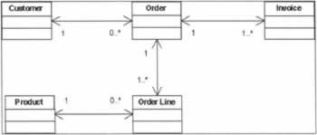
Using Class DiagramsThe most commonly used (or at least most commonly demonstrated) UML diagram is probable the Class Diagram. The Visio UML template calls it the Static Structure Diagram. Class diagrams illustrate the objects that compose a system and the relationships between those objects. Class diagrams can be written from one of two different perspectives - a logical approach to objects in a system and their relationships or a detailed, implementation-specific approach that includes methods, attributes, data types, etc. During early stages of a development project, it's common to use class diagrams to illustrate and communicate relationships between large conceptual objects in a system. We call these types of diagrams Conceptual Class Diagrams. For instance, in our order entry application, we would spend some time working out the relationships between Customers, Orders, Products, etc. The existence and relationships of these objects is important as we transition out of requirements development and into more application-oriented thinking. Here's an example of a simple conceptual class diagram: From this diagram, we can see the larger conceptual relationships of key objects in the application. For instance, we know from this diagram that every Order has to belong to one Customer. That's probably a logical arrangement and typical of most order entry applications. The diagram expresses that relationship using the association line end multiplicities 1 and 0..*. We also know that each Order object can somehow navigate back to its Customer and vice versa, a Customer object can identify its Order objects. The arrows on the lines indicate that to us. A similar amount of information is expressed in every other relationship in this diagram. For instance, every Order Line object has to have an Order and each Order Line has to navigate back to a Product. Working out relationships between key objects in an application is vital at this point in a development project. Once the details of attributes and methods of each object are added, the job of working out these relationships becomes harder, if, for no other reason than that there is a lot more information expressed about each class. You can also see how requirements are already playing a direct role in our architecture, and are expressed almost immediately in our UML diagrams. Consider the relationship between Customer and Order. If our users give us a requirement that any Order can be assigned to more than one Customer then we have a significant architecture issue to deal with. For one thing, it's not a common requirement of these types of applications. We easily could have assumed that Orders belonged to one Customer and that was it. After the first beta install or demo someone in the room would have asked to see the multiple Customer feature and one of our developers would have said "what's that?" and the room would get quiet for a few moments. Not a good scenario, is it? Once the conceptual relationships between objects are worked out, we'd hand off this class diagram to the detailed design stage of the project where methods and attributes of each class would be worked out in as much detail as possible.
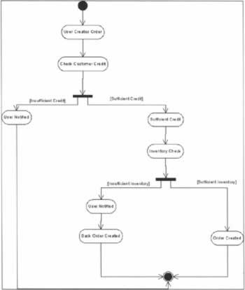
Using Activity DiagramsActivity Diagrams illustrate a sequence of tasks or actions taken by a user or external process. They tend to be detailed and are often found as supporting diagrams that help explain a particularly detailed portion of an application. They are also very useful when used at a high level to illustrate the flow of information or control through an application. Activity diagrams have the ability to nicely display branching for exception handling and other logical changes in the course of a process. For architecture purposes, it is sometimes nice to be able to express a series of major steps in an application and work through issues with other designers and developers. Although the term is ambiguous sometimes, most developers call the order of execution or process flow through an application its workflow. To illustrate workflow in our order-entry application we might create a diagram like this: Notice how the two simple decision points help illustrate the workflow of this particular application or group of applications. From an architectural standpoint, consider that each activity step is a separate application or something like a web service. The implications of working out workflow at this stage are very important. From a documentation standpoint, a diagram such as the simple one we've just seen would be valuable for several reasons:
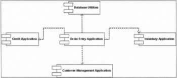
Using Component DiagramsThe last diagram we'll cover in the Architecture section is the component diagram. Although these diagrams are typically used to illustrate the physical implementation of binary files like an EXE or DLL, you might find them useful during the early stages of a project. For one thing, start thinking early about how you'll roll out your product. From experience, I've dealt with messy implementations that could have been averted had we dealt with installation and rollout issues from the beginning. Often, it's an easy process to sit down with a design and look ahead to predict issues that may arise when it comes time to deploy. It also helps to instill the thinking in the development team that the only real goal of a development project is to ship software. If you start sketching components and deployments early in a project, you'll get people thinking about shipping software instead of thinking in conceptual terms. That's an easy trap at this stage of the project - abstract designs always work on the whiteboard. Start with the end in mind and your chances of delivering a successful product increase. For those more pessimistic types, we can restate that last point: if you start with the end in mind your chances of failing decrease. So, what does a component diagram look like at this stage? Well, it's not too different from component diagrams anywhere else in a project. They aren't very complicated diagrams. In fact, at this point in the project, a component diagram is really more of a conversation starter used to illustrate some assumptions about how best to package your code. Let's have a look: It's immediately obvious that our Order Entry Application has quite a few dependencies - a Credit Application, an Inventory Application, and a Customer Management Application. From an architecture standpoint, the benefits of expressing the relationships between several applications and our new Order Entry application are obvious.
| |||||||||||||||||||||||||||||||||||

EAN: N/A
Pages: 85