Detailed Design Documentation
|
After a project has progressed through requirements development and architecture, project members are hopefully ready to begin working on the details of the application design. As we saw in our introductory discussion of detailed design, we expect to use documentation produced during the previous two project stages to help craft design documents in enough detail to hand to coders. Even well run projects incur some risk as this point. For one thing, the detailed design of an application is the first time any substantial test of basic architecture is done. The test isn't necessarily a formal test and review of architecture decisions; rather, it's a casual, incremental review done by all of the developers and designers associated with the project. Designers and developers responsible for portions of the application will be testing the design for soundness and adapting the basic design into their own detail designs. The effect is a continual review of the application architecture until everyone responsible for different portions of a detailed design is comfortable with their own pieces. By exposing architecture and high-level decisions to a variety of other developers, the project runs the risk of losing any core design principles that application architects were motivated by. Regardless of how a project's architecture and requirements are received by other members of the project team, there are some commonly used UML diagrams to express detailed design. In this section, we'll review the use of class diagrams, sequence diagrams, and state diagrams. In the case of class diagrams, we'll note differences between their usage at this stage of a project and the usage we saw during earlier, architecture stages. Sequence diagrams are one of my personal favorites for expressing the flow of messages between detailed components or objects within an application. Let's start with Class Diagrams.
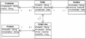
Using Detailed Class DiagramsThe biggest difference between the usage of class diagrams during detailed design and class diagrams during architecture is the level of detail we'll build into the diagrams. Previously we've been more interested in expressing relationships between major application objects and acknowledging the presence of application objects. At this point in a project, we are concerned with filling in the details of what interface each class will support. Although we won't be coding yet, at this point our class diagrams are being written with the intention of using them to generate code using a tool like Visio or having a developer write code that mirrors exactly what is contained in the class diagram. Like most things, it's best to see an example then discuss it. Here's our conceptual class diagram from earlier in the chapter reworked to contain implementation details. The first thing we notice is the addition of details about each one of our original conceptual classes. In this simple example, it's reasonable to expect that each conceptual class will map to one detailed design class. That isn't always the case, though. Complicated objects and complicated relationships between objects often get broken into small groups of detailed design objects. It's similar to a logical many-to-many relationship between two database tables. Showing the logical relationship is easy; just draw a line with 1...* at each endpoint. Actually implementing that relationship in a SQL database, however, requires an additional table that lives between the two main data tables. Although we might be missing a lot of detail in our simple example, the differences between a conceptual class diagram and a detailed design version of the same diagram should be evident. As we said earlier, you should expect to be able to give a detailed class diagram to a developer to start building an application. In this case, the attributes of our classes are relatively terse - there aren't too many of them. However, we could easily take the class diagram above and build five classes just from the information we've been given. There are details within the class diagram that may not immediately be obvious to a casual observer. Notice the lines between the classes. They obviously contain multiplicity information - an Invoice can exist for only one Order, etc. We covered this briefly during the architecture discussion. The line ends themselves also have meaning - navigability. It's a fancy term for the idea that an object should be able to navigate from itself to the other classes it references. The easiest example to understand is Order and Order Line. An Order consists of one or more Order Line objects. That makes sense because Order Lines are just the products and quantities that make up the order, one Order Line for each Product (do you see that Order Line-Product relationship in the class diagram?). According to the class diagram each Order should know how to find its Order Lines and each Order Line should know to which Order it belongs. The arrows on each end of the line tell us this. This is a great example of the information that we need to include at the detailed design stage of our projects. The difference between including navigability information and omitting it until later can result in wasted time and effort on the part of our developers. It can also result in some sloppy code, as in this case. If our developers didn't logically understand that an Order needed some mechanism for managing its constituent Order Line objects, how would we have coded most of our order management components? Database lookups every time we accessed an Order and needed to generate a total order amount? Granted, this is a simple example, but the point should be clear - carefully consider what you document in your diagrams during detailed design. Even the simplest of omissions can have far-reaching consequences.
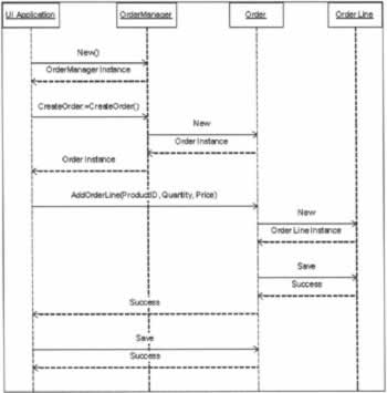
Using Sequence DiagramsOne of the best illustrations of how objects and the components that contain those objects communicate with one another is a Sequence Diagram. From a documentation standpoint, they are very useful to describing the order of messages from one object to another. By tracing messages from the top of the diagram to the bottom, it's easy to represent even complex messaging between several objects. Sequence diagrams, and their cousins the collaboration diagram, serve another purpose at this stage of a project. They help designers and developers work through final issues regarding what methods objects expose and what parameters are passed around between objects. A sequence diagram, in effect, allows developers to role-play by diagramming request and response messages from one object to another. By watching messages and their payloads (input and output parameters) flow from one object to another, we can see how objects should interact with each other once they are built. To illustrate let's add a new object to the group we've already been working with. It's only responsibility it to manage the order creation process. Since the object will be full of business rules, it could reside in a middle tier. Let's call it the OrderManager Front-end application will use the OrderManager to request new Order objects. Via the Order object that is created, applications can create Order Lines, save Orders, etc. Using the sequence diagram we can work through all kinds of issues including how and when object instances get created, the order of method calls from one object to another, what kinds of input and output parameters are necessary to perform some work. Sequence diagrams are really useful once you've worked about a fundamental detailed class diagram. Here are our Order and Order Line objects at work with the new Order Manager: Some of the issues this diagram might bring up during the course of design discussions could include the creation and destruction of child object instances, methods of passing input parameters and methods of passing output parameters. Other issues might include management of errors that occur in the Order Line class and any behavior that's required by the OrderManager to report those errors back to the Ul Application. Using a sequence diagram helps focus on these kinds of issues. The sequence diagram we just created also helps team members working further down the project lifecycle. For one thing, it's a clear definition of the order in which our main working objects are created and which object is responsible from creating others. Testing and support team members might get involved in difficult troubleshooting scenarios where the order of object creation might help shed light on particularly difficult errors (or particularly difficult-to-translate error messages!). Another huge benefit of a sequence diagram from a documentation standpoint is the head start it gives developers who are asked to modify code a year after the product is released. How many times have you picked up code for a maintenance assignment and not had any idea where to start. Wouldn't a sequence diagram have helped to get you started in the right direction? At this point, we are ready to talk about the Coding and Implementation stages of a software project. This point marks the transition from being a producer of documentation to more or less a consumer of documentation. Of course coding and testing and related activities produce their own documents, but we are focusing on using UML as a documentation tool and not on other forms of documentation. A theme throughout this chapter has been producing documents for future use in addition the immediate need of requirements, architecture, and detailed design. Now is when we discuss how that need manifests itself and how we will see some of the benefits.
| |||||||||||||||||||||||||||||||||||

EAN: N/A
Pages: 85