Ethernet
| This section explores the details of Ethernet operation. Because Ethernet has long been sufficiently stable to operate as a plug-and-play technology, it is assumed by many to be a simple technology. In fact, the inner workings of Ethernet are quite intricate. Ethernet is a very mature technology. It is considered the switching technology of choice for almost every network environment. However, IPS protocols are relatively immature, so Ethernet is trailing FC market share in block-level storage environments. As IPS protocols mature, additional IPS products will come to market, and Ethernet will gain market share in block-level storage environments. Thus, it is important to understand Ethernet's inner workings. Ethernet Media, Connectors, Transceivers, and Operating RangesEthernet supports a very broad range of media, connectors, and transceivers. Today, most deployments are based on copper media for end node connectivity, but ISLs are often deployed on fiber media. Copper media and transceivers are less expensive than their fiber counterparts, but they do not support the same distances as their fiber counterparts. As transmission rates increase, the single-segment distance that can be traversed decreases. This phenomenon is prompting a slow industry-wide movement away from copper media. As new 10GE products come to market, the cable-plant upgrades from copper to optical that began when GE products came to market are expected to continue. Table 5-4 summarizes the media, connectors, transceivers, and operating ranges that are specified in IEEE 802.3-2002. The nomenclature used to represent each defined GE implementation is [data rate expressed in Mbps concatenated with the word "BASE"]-[PHY designator]. The term 1000BASE-X refers collectively to 1000BASE-SX, 1000BASE-LX and 1000BASE-CX.
The MT-RJ and LC fiber optic connectors are not listed in Table 5-4 because they are not specified in IEEE 802.3-2002. However, both are quite popular, and both are supported by most GE switch vendors. Many transceiver vendors offer 1000BASE-LX-compliant GBICs that exceed the optical requirements specified in 802.3-2002. These transceivers are called 1000BASE-LH GBICs. They typically support a maximum distance of 10km. Another non-standard transceiver, 1000BASE-ZX, has gained significant popularity. 1000BASE-ZX uses a 1550nm laser instead of the standard 1310nm laser. The 1000BASE-ZX operating range varies by vendor because it is not standardized, but the upper limit is typically 70100km. Table 5-5 summarizes the media, connectors, transceivers, and operating ranges that are specified in IEEE 802.3ae-2002 and 802.3ak-2004. The nomenclature used to represent each defined 10GE implementation is [data rate expressed in bps concatenated with the word "BASE"]-[transceiver designator concatenated with encoding designator].
Though IEEE 802.3ae-2002 does not specify which connectors may be used, the duplex SC style is supported by many 10GE switch vendors because the XENPAK, X2, and XPAK MSAs specify duplex SC. The XFP MSA supports several different connectors, including duplex SC. Note that 10GBASE-EW and 10GBASE-ER links that are longer than 30km are considered engineered links and must provide better attenuation characteristics than normal SMF links. Ethernet Encoding and SignalingAs stated in chapter 3, "Overview of Network Operating Principles," bit-level encoding schemes are used to provide clocking, maintain DC balance, facilitate bit error detection, and allow the receiver to achieve byte or word alignment with the transmitter. Bit-level encoding schemes often define special control characters and frames which cannot be used to represent upper-layer data. Serial networking technologies typically use these special control frames along with designated fields in the headers of data frames to signal between devices. The information signaled between devices includes supported communication parameters, start of frame, end of frame, type of frame, priority of frame (for QoS), flow-control status, destination address, source address, ULP (for protocol multiplexing), error information, and so on. Ethernet uses several encoding schemes. This section discusses GE and 10GE encoding. FE encoding, while potentially relevant to modern storage networks, is considered outside the scope of this book. Table 5-6 lists the encoding scheme used by each GE and 10GE implementation and the associated BER objective.
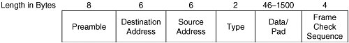
The 8B/10B encoding scheme generates 10-bit characters from 8-bit characters. Each 10-bit character is categorized as data or control. Control characters are used to indicate the start of control frames. Control frames can be fixed or variable length. Control frames can contain control and data characters. The set of characters in each control frame must be in a specific order to convey a specific meaning. Thus, control frames are called ordered sets. Fiber-based implementations of GE use the 8B/10B encoding scheme. GE uses only five of the control characters defined by the 8B/10B encoding scheme. These control characters are denoted as K23.7, K27.7, K28.5, K29.7, and K30.7. GE uses variable-length ordered sets consisting of one, two, or four characters. GE defines eight ordered sets. Two ordered sets are used for auto-negotiation of link parameters between adjacent devices. These are called Configuration ordered sets and are denoted as /C1/ and /C2/. Each is four characters in length consisting of one specified control character followed by one specified data character followed by two variable data characters. The last two data characters represent device configuration parameters. Two ordered sets are used as fillers when no data frames are being transmitted. These are called Idle ordered sets. They are denoted as /I1/ and /I2/, and each is two characters in length. Idles are transmitted in the absence of data traffic to maintain clock synchronization. The remaining four ordered sets are each one character in length and are used to delimit data frames, maintain inter-frame spacing, and propagate error information. These include the start_of_packet delimiter (SPD) denoted as /S/, end_of_packet delimiter (EPD) denoted as /T/, carrier_extend denoted as /R/, and error_propagation denoted as /V/. Copper-based implementations of GE use the 8B1Q4 encoding scheme. The 8B1Q4 encoding scheme is more complex than the 8B/10B encoding scheme. Eight data bits are converted to a set of four symbols, which are transmitted simultaneously using a quinary electrical signal. The individual symbols are not categorized as data or control, but each four-symbol set is. There are 31 four-symbol sets designated as control sets. These are used to delimit data frames, maintain inter-frame spacing, and propagate error information. Like 8B/10B implementations of GE, 8B1Q4 implementations support auto-negotiation of link parameters between adjacent devices. This is accomplished via the fast link pulse (FLP). The FLP is not a four-symbol set, but it is defined at OSI Layer 1, and it does have ordered bit positions. The FLP consists of 33 bit positions containing alternating clock and data bits: 17 clock bits and 16 data bits. The FLP data bits convey device capabilities. Some 10GE implementations use 8B/10B encoding but do so differently than GE. The following definitions and rules apply to CWDM and parallel implementations. 10GE uses seven control characters denoted as K27.7, K28.0, K28.3, K28.4, K28.5, K29.7, and K30.7. With the exception of K30.7, these are used to identify ordered sets. The K30.7 control character is used for error control and may be transmitted independently. 10GE implementations based on 8B/10B use 10 fixed-length ordered sets consisting of four characters. Three ordered sets are defined to maintain clock synchronization, maintain inter-frame spacing, and align parallel lanes. These are collectively classified as Idle and include Sync Column denoted as ||K||, Skip Column denoted as ||R||, and Align Column denoted as ||A||. Five ordered sets are defined to delimit data frames. These are collectively classified as Encapsulation and include Start Column denoted as ||S||, Terminate Column in Lane 0 denoted as ||T0||, Terminate Column in Lane 1 denoted as ||T1||, Terminate Column in Lane 2 denoted as ||T2||, and Terminate Column in Lane 3 denoted as ||T3||. Two ordered sets are defined to communicate link-status information. These include Local Fault denoted as ||LF|| and Remote Fault denoted as ||RF||. Serial implementations of 10GE use the 64B/66B encoding scheme. The 64B/66B encoding scheme generates a 64-bit block from two 32-bit words received from the 10-Gigabit Media Independent Interface (XGMII). Two bits are prepended to each 64-bit block to indicate whether the block is a data block or a control block. Data blocks contain only data characters. Control blocks can contain control and data characters. There are 15 formats for control blocks. The first byte of each control block indicates the format of the block and is called the block type field. The remaining seven bytes of each control block are filled with a combination of 8-bit data characters, 7-bit control characters, 4-bit control characters, and single-bit null character fields. There are two 7-bit control characters: Idle and Error. These are used to maintain inter-frame spacing, maintain clock synchronization, adapt clock rates, and propagate error information. There is one four-bit control character: the Sequence ordered set character denoted as /Q/. 10GE ordered sets are embedded in control blocks. Each ordered set is fixed length and consists of a single 4-bit control character followed or preceded by three 8-bit data characters. The Sequence ordered set is used to adapt clock rates. One other ordered set is defined, but it is not used. The null character fields are interpreted as Start or Terminate control characters, which delimit data frames. The value of the block type field implies that a frame delimiter is present and conveys the position of the null character fields. This eliminates the need for explicit coding of information in the actual Start and Terminate control characters. In fact, these control characters are completely omitted from some frame-delimiting control blocks. Further details of each encoding scheme are outside the scope of this book. The 8B/10B encoding scheme is well documented in clause 36 of the IEEE 802.3-2002 specification and clause 48 of the IEEE 802.3ae-2002 specification. The 8B1Q4 encoding scheme is well documented in clause 40 of the IEEE 802.3-2002 specification. The 64B/66B encoding scheme is well documented in clause 49 of the IEEE 802.3ae-2002 specification. Ethernet Addressing SchemeEthernet does not implement any equivalent to SAM device or port names. However, Ethernet does implement an equivalent to SAM port identifiers. Ethernet devices use MAC-48 addresses to forward frames. Use of the MAC-48 address format in all Ethernet implementations simplifies communication between Ethernet devices operating at different speeds and preserves the legacy Ethernet frame formats. In the context of Ethernet, a MAC-48 address is often called a MAC address. In this book, the terms MAC-48 address and MAC address are used interchangeably. Ethernet Name Assignment and ResolutionEthernet does not implement SAM names, so name assignment and resolution mechanisms are not required. Ethernet Address Assignment and ResolutionEach Ethernet interface has a single MAC address "burned in" during the interface manufacturing process. If a NIC has more than one port, each port is assigned its own MAC address during the interface manufacturing process. This eliminates the need for network administrators to manage the Ethernet address space. A NIC's MAC address is used as the source address in all frames (unicast, multicast, and broadcast) transmitted from that NIC and as the destination address in all unicast frames sent to that NIC. Ethernet multicast addressing is currently outside the scope of this book. Broadcast traffic is sent to the reserved MAC address FF-FF-FF-FF-FF-FF. All Ethernet devices that receive a frame sent to the broadcast address process the frame to determine the ULP. If the ULP carried within the frame is active within the receiving node, the payload of frame is passed to the specified ULP for further processing. Otherwise, the frame is discarded. Because the MAC-48 addressing scheme provides global uniqueness, VLANs can be merged without risk of address conflicts. Note that some host operating system vendors subscribe to the philosophy that a multihomed host (that is, a host with multiple network interfaces) should be uniquely identified across all its Ethernet interfaces. By using and advertising a single MAC address (taken from one of the installed Ethernet interfaces) on all installed Ethernet interfaces, the host assumes a single Ethernet identity as viewed by all other attached network devices. This requires network administrators to take extra steps to ensure that network communication occurs as desired between the attached networks. In IP networks, Ethernet address resolution can occur in two ways: dynamically or statically. As discussed in chapter 3, "Overview of Network Operating Principles," ARP facilitates dynamic resolution of an Ethernet address when the IP address of the destination node is known. To dynamically discover the Ethernet address of another node, the IP stack in the source node invokes ARP to broadcast a frame containing its own IP address, its own Ethernet MAC address, the IP address of the destination node, and an empty field for the Ethernet MAC address of the destination node. All nodes attached to the Ethernet network receive and process this frame by updating their ARP tables with a new entry that maps the IP address of the source node to the Ethernet MAC address of the source node. In addition, the destination node replies to the originator of the ARP request. The unicast reply contains all the information from the original request frame, and the missing Ethernet MAC address. Upon receipt, the originator of the ARP request updates its ARP table with a new entry that maps the IP address of the destination node to the Ethernet MAC address of the destination node. Alternately, system administrators can create static mappings in the ARP table on each host. Static mappings typically are used only in special situations to accomplish a particular goal. Ethernet Media AccessAs stated in chapter 3, "Overview of Network Operating Principles," Ethernet uses CSMA/CD to arbitrate access to shared media. In switched implementations, arbitration is not required because full-duplex communication is employed on "private" media accessed by only one pair of devices. It is possible for a node to negotiate half-duplex mode when connected to a switch, but this suboptimal condition typically is corrected by the network administrator as soon as it is discovered. Collision-free line-rate performance is achievable if a switched Ethernet network is designed as such. This book does not discuss CSMA/CD in depth because modern storage networks built on Ethernet are switched. Ethernet Network BoundariesAn Ethernet network can be physically or logically bounded. Physical boundaries are delimited by media terminations (for example, unused switch ports) and end node interfaces (for example, NICs). No control information or user data can be transmitted between Ethernet networks across physical boundaries. Logical boundaries are delimited by OSI Layer 3 entities (for example, logical router interfaces within a multilayer switch). No OSI Layer 2 control information is transmitted between Ethernet networks across logical boundaries. User data is transmitted between Ethernet networks across logical boundaries by removing the Ethernet header and trailer, processing the packet at OSI Layer 3, and then generating a new Ethernet header and trailer. In the process, the source and destination Ethernet addresses are changed. Figure 5-5 illustrates the physical boundaries of an Ethernet network. Figure 5-5. Ethernet Network Boundaries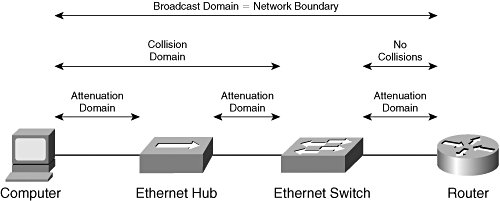 An Ethernet network also can have virtual boundaries. The IEEE 802.1Q-2003 specification defines a method for implementing multiple VLANs within a single physical LAN. In the simplest scenario, each switch port is statically assigned to a single VLAN by the network administrator. As frames enter a switch from an end node, the switch prepends a tag to indicate the VLAN membership of the ingress port (known as the Port VLAN Identifier (PVID)). The tag remains intact until the frame reaches the egress switch port that connects the destination end node. The switch removes the tag and transmits the frame to the destination end node. Ethernet switches use PVIDs to ensure that no frames are forwarded between VLANs. Thus, VLAN boundaries mimic physical LAN boundaries. User data can be forwarded between VLANs only via OSI Layer 3 entities. Note that the PVID can be assigned dynamically via the Generic Attribute Registration Protocol (GARP) VLAN Registration Protocol (GVRP). When GVRP is used, the PVID is typically determined by the MAC address of the end node attached to the switch port, but other classifiers are permitted. GVRP allows end nodes to be mobile while ensuring that each end node is always assigned to the same VLAN regardless of where the end node attaches to the network. Note also that a switch port can belong to multiple VLANs if the switch supports VLAN trunking as specified in IEEE 802.1Q-2003. This is most commonly used on ISLs, but some NICs support VLAN trunking. An end node using an 802.1Q-enabled NIC may use a single MAC address in all VLANs or a unique MAC address in each VLAN. In the interest of MAC address conservation, some 802.1Q-enabled NICs use a single MAC address in all VLANs. This method allows NIC vendors to allocate only one MAC address to each 802.1Q-enabled NIC. For these end nodes, GVRP cannot be configured to use the MAC address as the PVID classifier. Also, switch vendors must take special measures to forward frames correctly in the presence of this type of end node. These are the same measures required in environments where a host operating system advertises a single MAC address on all NICs installed in a multihomed host. An end node using an 802.1Q-enabled NIC may not forward frames between VLANs except via an OSI Layer 3 process. Ethernet Frame FormatsThe basic Ethernet frame format has changed little since the early days of Ethernet. Today, there are two variations of the basic frame format. These differ from each other only slightly. However, two other frame formats are defined, which build upon the basic format by including one or two additional subheaders. Figure 5-6 illustrates the IEEE 802.3-2002 frame format, which is one of the two variations of the basic frame format. Figure 5-6. IEEE 802.3-2002 Frame Format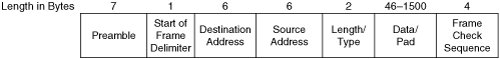 The Preamble and Start of Frame Delimiter are not considered part of the actual frame. These fields are discussed in this section for the sake of completeness. A brief description of each field follows:
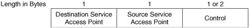
The other variation of the basic frame format is the Ethernet II frame format. Most Ethernet networks continue to use the Ethernet II frame format. The only differences between the Ethernet II format and the 802.3-2002 format are the SFD field and the Length/Type field. In the Ethernet II format, the recurring preamble bit pattern continues for eight bytes and is immediately followed by the DA field. The Ethernet II format does not support the length interpretation of the Length/Type field, so the field is called Type. Figure 5-7 illustrates the Ethernet II frame format. Figure 5-7. Ethernet II Frame Format When the IEEE first standardized Ethernet, the Length/Type field could only be interpreted as length. A mechanism was needed to facilitate ULP multiplexing to maintain backward compatibility with Ethernet II. So, an optional subheader was defined. The current version is specified in IEEE 802.2-1998. This subheader embodies the data component of the Logical Link Control (LLC) sublayer. This subheader is required only when the 802.3-2002 frame format is used and the Length/Type field specifies the length of the data field. When present, this subheader occupies the first three or four bytes of the Data/Pad field and therefore reduces the maximum amount of ULP data that the frame can transport. Figure 5-8 illustrates the IEEE 802.2-1998 subheader format. Figure 5-8. IEEE 802.2-1998 Subheader Format A brief description of each field follows:
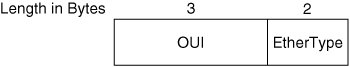
Like Ethertypes, service access points (SAPs) are administered by the IEEE to ensure global uniqueness. Because the Type field in the Ethernet II header is 16 bits, the 8-bit DSAP field in the LLC subheader cannot accommodate as many ULPs. So, another optional subheader was defined by the IETF via RFC 1042 and was later incorporated into the IEEE 802 Overview and Architecture specification. Referred to as the Sub-Network Access Protocol (SNAP), this subheader is required only when the 802.3-2002 frame format is used, the Length/Type field specifies the length of the data field, the 802.2-1998 subheader is present, and the ULP is not an IEEE registered SAP. When present, this subheader follows a 3-byte LLC subheader and occupies an additional 5 bytes of the Data/Pad field. Thus, the maximum amount of ULP data that the frame can transport is further reduced. The DSAP and SSAP fields of the LLC subheader each must contain the value 0xAA or 0xAB, and the CTL field must contain the value 0x03 to indicate that the SNAP subheader follows. The two fields of the SNAP subheader are sometimes collectively called the Protocol Identifier (PID) field. Figure 5-9 illustrates the IEEE 802-2001 subheader format. Figure 5-9. IEEE 802-2001 Subheader Format A brief description of each field follows:
In shared media environments, frames of different formats can traverse a shared link. However, each Ethernet interface is normally configured to use only one frame format. All devices using a given frame format can communicate, but they are isolated from all devices using other frame formats. When a device receives a frame of a different format, the frame is not understood and is dropped. One notable exception is a protocol analyzer that can support promiscuous mode. Promiscuous mode enables a device to transmit and receive all frame formats simultaneously. In switched environments, a similar phenomenon of isolation occurs. Each switch port must be configured to use only one frame format. Each end node must use the same frame format as the switch port to which it is attached. When a switch forwards multicast and broadcast traffic, only those switch ports using the same frame format as the source node can transmit the frame without translation. All other switch ports must translate the frame format or drop the frame. Translation of every frame can impose unacceptable performance penalties on a switch, and translation is not always possible. For example, some Ethernet II frames cannot be translated to LLC format in the absence of the SNAP subheader. So, Ethernet switches do not translate frame formats. (VLAN trunking ports are a special case.) Thus, Ethernet switches drop frames when the frame format of the egress port does not match the frame format of the source node. This prevents ARP and other protocols from working properly and results in groups of devices becoming isolated. For this reason, most Ethernet networks employ a single frame format on all switch ports and attached devices. As previously stated, VLANs require each frame sent between switches to be tagged to indicate the VLAN ID of the transmitting node. This prevents frames from being improperly delivered across VLAN boundaries. There are two frame formats for Ethernet trunking: the IEEE's 802.1Q-2003 format and Cisco Systems' proprietary ISL format. Today, most Ethernet networks use the 802.1Q-2003 frame format, which was first standardized in 1998. So, Cisco Systems' proprietary frame format is not discussed herein. Figure 5-10 illustrates the IEEE 802.1Q-2003 frame format. Figure 5-10. IEEE 802.1Q-2003 Frame Format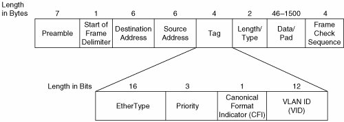 A brief description of each Tag sub-field follows:
The brief field descriptions provided in this section do not encompass all the functionality provided by each of the fields. For more information, readers are encouraged to consult the IEEE 802.3-2002, 802.2-1998, 802-2001, and 802.1Q-2003 specifications. Ethernet Delivery MechanismsEthernet is often mistakenly considered to be a connectionless technology. In fact, Ethernet provides three types of service via the LLC sublayer. These include the following:
Most Ethernet switches provide only unacknowledged, connectionless service (Type 1), which contributes to the public's misunderstanding of Ethernet's full capabilities. Because the other two service types are rarely used, the delivery mechanisms employed by the LLC sublayer to provide those types of service are outside the scope of this book. Ethernet networks that provide Type 1 service implement the following delivery mechanisms:
Ethernet Link AggregationClause 43 of IEEE 802.3-2002 defines a method for aggregation of multiple Ethernet links into a single logical link called a Link Aggregation Group. Link Aggregation Groups are commonly called Ethernet port channels or EtherChannels. Despite the fact that the term EtherChannel is copyrighted by Cisco Systems, the term is sometimes used generically to describe Ethernet port channels implemented on other vendors' equipment. Automation of link aggregation is supported via the IEEE's Link Aggregation Control Protocol (LACP). With LACP, links that can be aggregated will be aggregated without the need for administrative intervention. The LACP frame format contains 31 fields totaling 128 bytes. Because of the complexity of this protocol, granular description of its operation is currently outside the scope of this book. Before standardization of LACP in 2000, Cisco Systems introduced automated link aggregation via the Port Aggregation Protocol (PAgP). The details of PAgP have not been published by Cisco Systems. Thus, further disclosure of PAgP within this book is not possible. Both link aggregation protocols are in use today. The protocols are quite similar in operation, but they are not interoperable. Automated link aggregation lowers (but does not eliminate) administrative overhead. Network administrators must be wary of several operational requirements. The following restrictions apply to Ethernet port channels:
Some of these restrictions are not specified in 802.3-2002, but they are required for proper operation. Similarly, there is no de jure limit on the maximum number of links that may be grouped into a single port channel or the maximum number of port channels that may be configured on a single switch. However, product design considerations may impose practical limits that vary from vendor to vendor. The 802.3-2002 specification seeks to minimize the probability of duplicate and out-of-order frame delivery across an Ethernet port channel. However, it is possible for these outcomes to occur during reconfiguration or recovery from a link failure. Ethernet Link InitializationEthernet link initialization procedures are the same for node-to-node, node-to-switch, and switch-to-switch connections. However, different procedures are observed for different types of media. FE and GE links may be configured manually or configured dynamically via auto-negotiation. 10GE does not currently support auto-negotiation. Most NICs, router interfaces, and switch ports default to auto-negotiation mode. Ethernet auto-negotiation is implemented in a peer-to-peer fashion. Clause 37 of IEEE 802.3-2002 defines auto-negotiation for 1000BASE-X. As previously stated, auto-negotiation is accomplished via ordered sets in 1000BASE-X implementations. Therefore, 1000BASE-X implementations do not support auto-negotiation of the transmission rate because bit-level synchronization must occur before ordered sets can be recognized. So, if a 1000BASE-X device is connected to a 100BASE-FX (fiber-based FE) device, the link will not come up. When two 1000BASE-X devices are connected, operating parameters other than transmission rate are negotiated via the Configuration ordered sets /C1/ and /C2/ (collectively denoted as /C/). All capabilities are advertised to the peer device by default, but it is possible to mask some capabilities. If more than one set of operating parameters is common to a pair of connected devices, a predefined priority policy determines which parameter set will be used. The highest common capabilities are always selected. As previously stated, each /C/ ordered set carries two bytes of operating parameter information representing the transmitter's 16-bit configuration register (Config_Reg). Immediately following link power-on, alternating /C1/ and /C2/ ordered sets containing zeroes in place of the Config_Reg are transmitted by each device. This allows the other device to achieve bit-level synchronization. Upon achieving bit-level synchronization, the receiving device begins searching the incoming bit stream for the Comma bit pattern (contained within the /K28.5/ control character) and begins transmitting alternating /C1/ and /C2/ ordered sets containing the Config_Reg. Upon recognition of the Comma bit pattern in three consecutive /C/ ordered sets without error, the receiving device achieves word alignment and begins searching the incoming bit stream for the Config_Reg. Upon recognition of three consecutive, matching Config_Regs without error, the receiving device sets the Acknowledge bit to one in its Config_Reg, continues transmitting until the Link_Timer expires (10ms by default) and begins resolving a common parameter set. If a matching configuration is resolved, normal communication ensues upon expiration of the Link_Timer. If successful negotiation cannot be accomplished for any reason, the network administrator must intervene. Figure 5-11 illustrates the 1000BASE-X Configuration ordered sets. Figure 5-11. 1000BASE-X Configuration Ordered Sets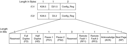 A brief description of each field follows:
The preceding description of the 1000BASE-X link initialization procedure is simplified for the sake of clarity. For more detail about /C/ ordered set usage, Next Page formats, field interpretations, and auto-negotiation states, readers are encouraged to consult clause 37 and all associated annexes of IEEE 802.3-2002. Clause 28 of IEEE 802.3-2002 defines auto-negotiation for all Ethernet implementations that use twisted-pair cabling. As previously stated, auto-negotiation is accomplished via the FLP in twisted-pair based GE implementations. The FLP mechanism is also used for auto-negotiation in 100-Mbps twisted-pair based Ethernet implementations (100BASE-TX, 100BASE-T2, and 100BASE-T4). A special mechanism is defined for 10BASE-T implementations because 10BASE-T does not support the FLP. Because 10BASE-T is irrelevant to modern storage networks, only the FLP mechanism is discussed in this section. The 16 data bits in the FLP are collectively called the link code word (LCW). The LCW represents the transmitter's 16-bit advertisement register (Register 4), which is equivalent to the 1000BASE-X Config_Reg. Like 1000BASE-X, all capabilities are advertised to the peer device by default, but it is possible to mask some capabilities. If more than one set of operating parameters is common to a pair of connected devices, a predefined priority policy determines which parameter set will be used. The highest common capabilities are always selected. Unlike 1000BASE-X, the FLP is independent of the bit-level encoding scheme used during normal communication. That independence enables twisted-pair based Ethernet implementations to auto-negotiate the transmission rate. Of course, it also means that all operating parameters must be negotiated prior to bit-level synchronization. So, the FLP is well defined to allow receivers to achieve temporary bit-level synchronization on a per-FLP basis. The FLP is transmitted immediately following link power-on and is repeated at a specific time interval. In contrast to the 1000BASE-X procedure, wherein /C/ ordered sets are initially transmitted without conveying the Config_Reg, twisted-pair based implementations convey Register 4 via the LCW in every FLP transmitted. Upon recognition of three consecutive matching LCWs without error, the receiving device sets the Acknowledge bit to one in its LCW, transmits another six to eight FLPs, and begins resolving a common parameter set. If a matching configuration is resolved, transmission of the Idle symbol begins after the final FLP is transmitted. Transmission of Idles continues until bit-level synchronization is achieved followed by symbol alignment. Normal communication then ensues. If successful negotiation cannot be accomplished for any reason, the network administrator must intervene. Figure 5-12 illustrates the Ethernet FLP LCW. Figure 5-12. Ethernet FLP Link Code Word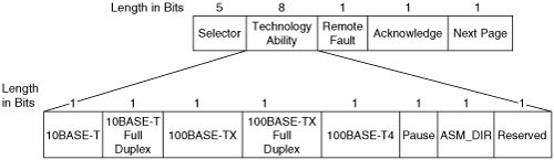 A brief description of each field follows:
The preceding description of the twisted-pair based Ethernet link initialization procedure is simplified for the sake of clarity. For more detail about FLP usage, Next Page formats, field interpretations, and auto-negotiation states, readers are encouraged to consult clause 28 and all associated annexes of IEEE 802.3-2002. The IEEE 802.3-2002 specification recommends that manual configuration be achieved not by disabling auto-negotiation, but by masking selected capabilities when advertising to the peer device. This choice is vendor dependent. The remainder of this paragraph describes the procedures followed when auto-negotiation is disabled. When manually configuring an interface, the network administrator typically is allowed to specify the transmission rate and duplex mode of each twisted-pair interface. For fiber interfaces, the transmission rate is fixed and cannot be altered, but the duplex mode can be specified. Some products allow additional granularity in manual configuration mode. In the absence of additional granularity, network administrators must consult the product documentation to determine the default values of operating parameters that cannot be explicitly configured. As previously stated, the order of events following power-on depends on the media type. For 1000BASE-X, bit level synchronization is achieved followed by word alignment. Normal communication is then attempted. If compatible operating parameters are configured, successful communication ensues. Otherwise, the link might come up, but frequent errors occur. For twisted-pair interfaces, bit-level synchronization is attempted. If successful, symbol alignment occurs. Otherwise, the link does not come online. Once symbol alignment is achieved, normal communication is attempted. If compatible operating parameters are configured, successful communication ensues. Otherwise, the link might come up, but frequent errors occur. If a manually configured link cannot come up or experiences frequent errors because of operating parameter mismatch, the network administrator must intervene. |
EAN: 2147483647
Pages: 196