| In Chapter 2, you learned how to switch from Wireframe to Shaded mode (hotkeys: 4 and 5) and how to change the detail level of NURBS objects (hotkeys: 1, 2, or 3). Some other display options can help you see your object more clearly or speed up interaction. If you choose Shading | Shade Options in the panel's menu, you'll find options to display Wireframe on Shaded Objects and X-Ray mode. These options can be helpful when you need special, slower rendering display modes in Shaded mode to help solve a problem. Wireframe on Shaded Objects can help you visualize curvatures better and see the effects of editing an object's shape more clearly. X-Ray mode makes the shaded objects in the 3D view semi-transparent. You can see through all objects without giving up the three-dimensional look of Shaded mode. Other options speed the interactivity of shaded views. Under Shading | Interactive Shading on the panel menu, you'll find four options for degrading the display update when you are moving scene elements. As soon as you stop transforming objects or changing the view, the full shaded view returns. Often, complex scenes bog down the 3D shaded views so badly that you cannot easily move objects; the shaded view stops the movements constantly to refresh the display. That mode is called Normal in the Interactive Shading options. The other options Wireframe, Bounding Box, and Points switch the display to view the scene in those visual styles during viewport or object changes. Another interactivity speedup is under Display | Fast Interaction. When it's enabled, the shaded views simplify objects and textures under certain conditions to speed up the display. This option is popular and saves time without being too intrusive in its degradation of the displayed image during changes. Tutorial: Create, Select, Transform, Duplicate! Now, you can apply some of what you've learned to a brief, simple tutorial. You'll use a little bit from each of this chapter's sections to build a car object with wheels and a door. On the DVD  Chapter_03\movies\ch03tut01.wmv |
Start with a blank, empty workspace in Maya. Confirm that your history is on by making sure the Construction History button in the Status Line is activated. Choose Create | Polygon Primitives | Cube to create a cube object at the origin point that will be your car. In the Channel Box, set Translate Y to 1, Scale X to 6, and Scale Z to 3. At the top of the Channel Box, click on the name PolyCube and rename it as body. Next, add some divisions along the car: Click the word PolyCube under INPUTS (your object might have different numbers after the word PolyCube). Set Subdivisions Width to 5. On the DVD  Chapter_03\ch03tut01.mb |
Switch the Front view to full screen by tapping the spacebar over that view. Press F8 to enter Component mode editing. Now, you can select the points and move them to shape the car. Select groups of vertices by dragging a marquee, so that you select the vertices in front and back. Start by selecting the columns of vertices and adjusting them left and right, as shown in Figure 3.12. Then select the top sets of vertices and adjust their height to make the shape of a car. After you finish, press F8 to exit Component mode. The purple vertices should disappear, and the object should return to green wireframe lines. Figure 3.12. Adjusting vertices to form a car. The bottom copy is the original box, the middle is after adjusting the vertices horizontally, and the top shows the finished shape. 
Now, you create the wheels. Choose Create | Polygon Primitives | Cylinder to create the starting shape. In the Channel Box, click on the name PolyCylinder and rename it as tire1. Set its Rotate X to 90 in the Channel Box to turn it on its side. Next, set Scale Y to .2 to make it narrower. Farther down the Channel Box, click the PolyCylinder listing under INPUTS to see the creation settings for this cylinder. Set Radius to .6 to make the wheel smaller. Next, set Translate Y to 0.6 to put it on the ground plane. Now, you can position the tire correctly on the car by moving it in the Top view, or you can simply set Translate X to 2 and Translate Z to 1.5. Choose Edit | Duplicate to copy this wheel. To be safe, use the Duplicate Options dialog box, reset its settings, and then click Apply. The new copied tire is directly on top of the original. Set its Translate X to 2.0, and the duplicate moves to the back of the car. Now, Shift-click to select the original tire, and use the hotkey Ctrl+d to duplicate both. With both copies still selected, enter 1.5 for Translate Z, and the two duplicated tires jump to the other side of the car. In the Front view, drag a marquee around the bottom of the four tires. This selects all four tires, but not the body. Now, Shift-click to select the body. Next, choose Edit | Parent to make the wheels children of the car body. Now that the car body is the parent, when you move the car body, the wheels follow. Test this by switching to Move mode (hotkey: w) and move the car around. If you select a tire, you can move it without moving the car body. Also, with a tire selected, pressing the up arrow moves up the hierarchy and selects the car body and its children. Try this to see how it works. Next, you'll explore a problem with parents that have nonuniform scaling. Select a tire and rotate it in the Top view, in the Y (blue) axis. The tire warps as it rotates, as shown in Figure 3.13. That's because you made the car body by scaling a cube, and the car's children inherit this scaling factor. To fix it, you must first unparent the tires from the car. Do this by selecting the four tires (as you did in step 5), and then choose Edit | Unparent (hotkey: Shift+P). Figure 3.13. When the tire is rotated, it skews in an unexpected way. 
To get rid of the car body's nonuniform scale, "freeze" its transform that is, set its current state to a scale of 1/1/1. Do this by selecting the car body and choosing Modify | Freeze Transformations. Note: In the Channel Box, the car body values are set back to 0 for Transform and Rotate and to 1 for Scale. Reparent the tires to the car body by selecting the tires with a marquee, Shift-clicking to select the body (to make sure it's the last thing selected), and pressing p. Rotate the tires, and you can see the skew is no longer there. Now, create a door for the side of the car. Create a polygon cube, as in step 1, and name it door. Set its Subdivisions Width and Height to 2. Set its Translate Y to 1, Translate Z to 1.5, and Scale Z to 0.1. These settings get the door in place. Switch to the Front view and tap the spacebar to go to full screen. With the car door still selected, press F8 to enter Component mode. As you did earlier with the car body, adjust the door's vertices to make it fit the car body (see Figure 3.14). Make sure to select vertices by dragging a marquee so that both front and back vertices of the box object are selected. After you finish, press F8 to exit Component mode. Figure 3.14. Adjusting the door's vertices to fit the side of the car. 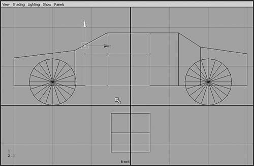
Try to rotate the door in the Y axis (the green line in the rotate manipulator). The door does not rotate at the point where you would expect the hinge the front edge of the door. To see the door rotating into the car, switch to the Perspective view and set the panel controls Shading | Shade Options to X-Ray and Wireframe on Shaded. If needed, you can adjust the Perspective view so that the entire car is shown at a more convenient angle. Move the door's pivot point, using snapping to place it precisely. With the door still selected, enter Pivot Editing mode by pressing Insert (or the Home key on a Macintosh). You see the manipulator change to a different icon. Next, hold down the c key to force the movement to be curve-snapped. Finally, MMB-click (make sure you use the MMB) on the edge of the door, where the hinge should be aligned. As you MMB-drag, the pivot should jump to this line for easy placement (see Figure 3.15). Press Insert (or Home for Macintosh) again to exit Pivot Editing mode. Test your new pivot point by rotating the door again. Be sure to undo any test rotations by pressing Ctrl+z. Figure 3.15. Aligning the pivot point for the door. 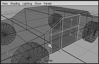
Parent the door to the car: Select the door, Shift-click to select the car, and then press p to parent. Test this by switching to Move mode (hotkey: w) and moving the car body object. All its tires and the door should follow. Add a handle to the door: Create a polygon cube and set its Scale X to 0.3, Scale Y to 0.1, and Scale Z to 0.05. Set its Translate X to 0.3, Translate Y to 1.2, Translate Z to 1.58. These settings should place the handle in an appropriate spot on the outer surface of the car door. Name it handle. Use the same technique as in step 12 to move the handle's pivot point to the upper inside edge: Press Insert (or Home), hold down c for the Snap to Curve option, and MMB-drag along the edge you want (see Figure 3.16). Exit Pivot Editing mode. Now, you can rotate the handle. Figure 3.16. Adjusting the pivot point for the door handle. 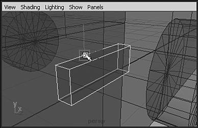
To connect the handle to the car, you need to parent it to the door. The door has scale factors applied, however. So first, freeze the door's transform by selecting it and choosing Modify | Freeze Transformations. Then, you can parent the handle to the door by selecting the handle, Shift-clicking to select the door, and then pressing p. Now that the car is all set up, you can enjoy the ease of animating it with this hierarchy. To create a little animation, first set the Time Slider to cover the full range 48 frames. Select the car body. (All the other parts will be selected, too, but you can confirm that you have only the car body selected by checking the Channel Box.) Press the s key to set a position key. A thin red line appears in the Time Slider to indicate this key. Set the Time Slider to 36 by LMB-dragging in it. Then, move the car a little to the left in the Top view. Press the s key to set a key here. LMB-drag through the Time Slider to view the animation you just made. tip As always, make sure your Caps Lock key is off. All Maya's hotkeys are case sensitive! Drag the Time Slider to 36. Select the door, and press s to set a key. Drag the Time Slider to 48. Switch to Rotate mode (hotkey: e), and rotate the door out in Y (the green handle in the manipulator). Or you can enter 60 in the Channel Box. Press s to set this key. Keep in mind that the s hotkey works only if you aren't typing in the Channel Box, so if you entered the value manually, press Enter or right-click in a 3D panel. Now, you can test-view this animation by dragging in the Time Slider or clicking the play button in the time controls at the lower right of the interface. Switch to the Perspective view, and you can adjust your viewing angle while the animation plays back to see it from different sides and judge your animation (see Figure 3.17). Figure 3.17. Adjusting your view angle while the animation plays back in the Perspective view. 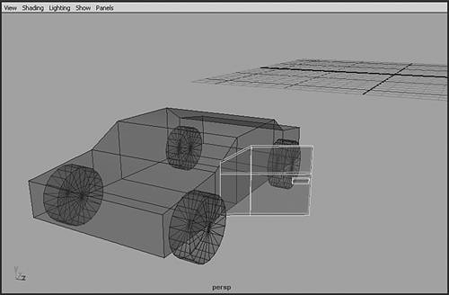
On the DVD Chapter_03\ch03tut01end.mb |
Going Further Create an animation for the door handle by making it rotate out just before the door begins to open and rotate back just after the door begins to open. Animate the car's tires turning while the car is moving. Also, explore all Maya's display modes to see the advantages of each one. Test the interactive speedup options to learn what they do to the Shaded view and to recognize the look. You might also want to test the duplication options to learn some of the possibilities they offer. As you advance in your skill level, try the concepts of grouping and movement in a car's tires with a higher-resolution model of a real car. The company 3d02 (http://www.3d02.com) specializes in building high-detail photorealistic car models. 3d02 has graciously contributed its model of the Ford Mustang (see Figure 3.18), which you can find on the DVD in the "goodies" folder along with other great free content. Figure 3.18. This Ford Mustang model was modeled by Elvis Blazencic and contributed to the book by 3d02. Lighting and rendering in Maya by Garry Lewis. 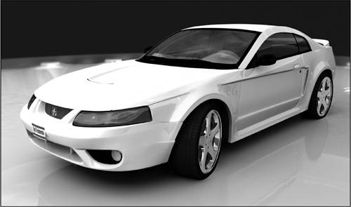
|
|