Chapter 7 - Building a TCPIP Router-Based Network

Chapter 7: Building a TCP/IP Router-Based Network  
  Objectives  
  In this chapter we will:  
    Examine various options for building your internetwork in a scalable, robust, manageable, and cost-effective manner.  
    Give some general guidelines and some options for each category, so you can choose which is most appropriate for your situation.  
    Apply selected technology options to construct a sample internetwork.
The Base Internetwork  
  Here we will outline the sample internetwork we will build at the end of this chapter. This internetwork will form the basis for discussion of implementation, security, backup, and management issues as we progress through the chapter. First, let's define what we want to connect together.  
  We will assume a data center in Chicago, where the head office also is located, and approximately 100 branch offices clustered around major cities, such as New York, Atlanta, Dallas, San Francisco, and Los Angeles. A typical branch office has 20 PCs that need access to hosts located in the Chicago data center, local applications, e-mail, and the Internet. There also is a growing need to support staff working from home and roving users with dial access.  
  The issues that need to be resolved are as follows:  
    Do I use InterNIC/IANA-assigned IP addresses, or make up my own?  
    What topology will be used?  
    What IP addressing scheme and routing protocol will I use?  
    What options are available for providing backup links in the event of line failure?  
    How do I minimize the manual-support burden for IP address and name resolution?  
    What reasonable security measures should I enforce?  
    How can I reduce support costs by making this internetwork easily manageable from one location?  
  These issues will form the basis of discussion for the following sections. With internetwork design, as with many other aspects of networked computing, many options are available, and each will be appropriate for one application and inappropriate for another. I hope to be fairly unbiased in my presentation of each option, but I will favor those solutions with which I have had the most success. The bulk of this chapter will discuss the options available to you for internetwork configuration. At the end of this chapter we will return to the aforementioned requirements and select appropriate configuration options to service them.
IANA or Not IANA?  
  IANA stands for the Internet Assigned Numbers Authority, which is essentially an independent body responsible for assigning Internet addresses, well-known port numbers, autonomous system numbers, and other centrally administered Internet resources. The people who actually assign IP addresses for use on the Internet in the United States are those at InterNIC. If you have to apply directly for Internet addresses (that is, if you do not want to go through an Internet service provider, or ISP), the documentation you have to fill out states that the InterNIC assigns Internet addresses under the authority of IANA. In Europe, address assignment is handled by the Resaux IP Europeans (RIPE), and the Asia Pacific Network Information Center (APNIC) assigns addresses in Asia.  
  The question is, do you use on your internetwork IP addresses that are globally valid on the Internet, or do you make up your own numbers to suit your particular internetwork's needs? Let's take a few moments to consider the benefits and pitfalls of each approach.  
  Assuming that a firewall of some kind is in place to separate your internetwork from the Internet (firewalls will be considered in more depth later in this chapter), the question boils down to: Should I use network address translation or a firewall's proxy server function to allow me the freedom of assigning my own addressing scheme, or do I want to get InterNIC addresses and be part of the global Internet addressing scheme?  
  We first should discuss the benefits of using a proxy server. If you have any concerns regarding security, it is appropriate to use a proxy server firewall machine as a single connection point from your internetwork to the Internet. A proxy server separates two networks from each other, but allows only prespecified communication between the two to occur. A proxy server has two sides, the inside (your internetwork) and the outside (the Internet), and is configured to allow only certain types of communication to take place.  
  This means that if you decide to allow outgoing Telnet sessions, and if a client PC on the inside of a proxy server wants to establish a Telnet session with a host on the outside of the proxy server (the Internet side), a direct Telnet session between the two machines will not be made. What does happen is that the client PC will establish a Telnet session with the proxy server, the proxy server will establish a separate session with the host on the Internet, and the proxy server will pass information between the two. As far as the client PC and the Internet host are concerned, they are talking to each other directly; in reality, however, the client PC is talking to the client side of the proxy server, and the Internet host is talking to the Internet side of the proxy server. The proxy server passes any traffic that we have previously determined is allowable onto the other side, and, optionally, logs all communications that have taken place.  
  As a side benefit, this type of server shields the internal network numbering scheme from the external network. This means that an Internet proxy firewall server will have a set of InterNIC-assigned addresses on the Internet side and some user-defined addressing scheme on the internal side. To enable communication between the two, the proxy server maps internal to external addresses.  
  If you choose to implement your own addressing, this proxy server feature gives you a lot of freedom to design an appropriate networking scheme for the internal network. Addresses assigned by the InterNIC are typically Class C addresses, which might not fit the internal network's needs. Also, the application process to get addresses directly from the InterNIC is arduous, to say the least.  
  The same benefits of shielding the internal network numbering scheme can be delivered by a network address translation server. An address translation server changes the addresses in packet headers, as packets pass through it. This type of server does not run any application software and does not require hosts to run proxy-aware applications.  
  There are, however, some potential issues related to implementing your own IP addressing scheme that are avoided when addresses are obtained from the InterNIC. The most obvious is that if you assign to your internal network a network number that already is in use on the Internet, you will not be able to communicate with the Internet sites using that address. The problem is that the routing table on the proxy server directs all packets destined for that network number back to the internal network.  
  The Internet Assigned Numbers Authority (IANA) foresaw this problem and reserved some Class A, B, and C network numbers for use by internal networks that were isolated from the Internet by a proxy server. These reserved addresses are as follows:  
  10.0.0.0  
  172.16.0.0 to 172.31.0.0  
  192.168.xxx.0  (where xxx is any value 0 255)  
  This means that any number of organizations can use these addresses for their internal networks and still be assured of reaching all Internet sites. This solution creates another problem, however, because firewalls are not used only to connect to the Internet. Corporations in increasing numbers are connecting their networks to each other and need to secure communications between the two. This is particularly true for information service companies that deliver their information to a client's network. If two organizations use 172.16.0.0 as their internal network, they cannot connect their networks together unless one of them renumbers. The only alternative to renumbering would be for the two corporations to go through a double address translation stage, which would be difficult to manage. There are some benefits to having InterNIC-assigned addresses on your internal network. You have the peace of mind of knowing that your network can be safely hidden from the Internet, yet you still have the ability to access every Internet site out there. In addition, if you need to connect to another company's network, you should be okay. The chances of any given organization implementing network address translation and choosing your assigned address for their internal network are small.  
  On the downside, using InterNIC addresses can be restrictive and can necessitate implementation of a very complex network numbering scheme. If you have only 200 hosts that need addresses, you are likely to get only one Class C address. If you are particularly unlucky during the appli-cation process, you will not even be assigned Class C addresses. Some applicants now are expected to use only portions of a Class C network address, which requires a routing protocol that supports discontinuous subnets. This may cause restrictions to network design, or at the very least, a complex numbering scheme that will prove difficult to troubleshoot.  
  I recommend that unless you already have adequate addresses assigned by the InterNIC, you do not use InterNIC-assigned numbers for your internal internetwork. Most people who implement network address translation will use the IANA-reserved addresses, typically the Class A network number 10. If you are concerned that you might need to connect your internetwork to another company that has implemented network number 10 for its internal network, use network number 4 or 5. These class A numbers are reserved for the military and are not present on the Internet.  
  The rest of this chapter will assume that we have decided to hide the internal network numbering scheme and are free to assign a network numbering scheme that makes things easy to administer.
Internetwork Topology  
  In general, we can identify three classes of service within an internetwork: backbone, distribution, and local services. These three levels of service define a hierarchical design. The backbone services are at the center of the hierarchy, and handle routing of traffic between distribution centers. The distribution centers are responsible for interfacing the backbone to the local services, which are located in each site. At each site, the local services connect individual hosts (multiuser machines and PC workstations) to the distribution network.  
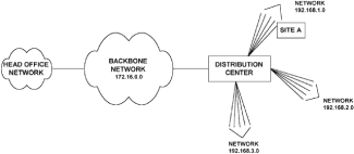
  In the requirement we have specified above, each major location, such as New York, Atlanta, and Los Angeles, becomes a distribution center, as illustrated in Fig. 7-1. The distribution center concept is a simple one in that it can be used to associate a specific range of IP addresses with one geographic location. This simplifies matters when troubleshooting, can reduce the size of routing tables, and hence can reduce the size of routing updates.  
   
  Figure 7-1: Distribution centers connected via a backbone network  
  This topology gives you the flexibility to implement either a distance vector or link state routing protocol. We shall now look at alternatives for interconnecting sites on the backbone.  
  Backbone Topologies  
  The following discussions are based on connecting the main centers together. The goals for this part of the hierarchy are high availability, higher levels of throughput, and the ability to add new distribution centers with a minimum of disruption of service to the internetwork as a whole.  
  Star Topology.     The star network topology is illustrated in Fig. 7-2, which shows Chicago in the center, with all lines emanating from there to the main locations. This topology is a simple one to understand and troubleshoot. It does, however, place a greater processing burden on the central router located in Chicago, because all traffic passing between distribution centers must pass through that router. In addition, only one full-time connection goes to each location. That means that if one of the main lines from a distribution center to the central site fails, all communication to or from that center stops until some dial backup mechanism reestablishes the link.  
   
  Figure 7-2: A backbone network utilizing a star topology  
  If the bandwidth necessary to provide full communications between a distribution center and the central site is greater than 128 kbps (what is achievable with a single ISDN connection), there are no simple and inexpensive ways to establish a dial backup connection. Multilink PPP is just becoming available, and there are some proprietary ways to perform what is termed inverse multiplexing, the combining of several ISDN connections and making them appear as one line. This could be an option for the star topology if you decide to implement it.  
  Ring Topology.    The ring topology, as its name suggests, forms a ring around all the main distribution centers (Fig. 7-3). The advantage is that each site has two permanent connections to it, so in the event of a single line failure, an alternate path is available to deliver traffic.  
   
  Figure 7-3: A backbone network utilizing a ring topology  
  The downside is that traffic destined for Dallas from Chicago has to pass along the link from Chicago to New York, then to Atlanta, and finally to Dallas. This places a higher bandwidth utilization on the Chicago-to-New-York link than is necessary, because that link is carrying traffic destined for Dallas. Also, since it uses more lines than the star topology, there is less likely to be money for a dial backup system, which is okay since there are two lines feeding each location. If any two lines fail, however, the network is down hard until one of them comes back.  
  Fully Meshed Topology.    This is the ultimate in resiliency, minimizing the number of intermediate routers through which traffic must pass, and reducing the amount of traffic on each link. The obvious drawback is the cost of all the leased lines. There are very few situations that justify a fully meshed network, because just adding one more distribution center to the backbone takes up significant resources in terms of router ports at each location. A fully meshed network is shown in Fig. 7-4.  
   
  Figure 7-4: A backbone network utilizing a fully meshed topology  
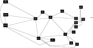
  Partially Meshed Topology.     The concept behind the partially meshed network should be familiar to all those who have been involved in internetwork design, and that concept is compromise. The partially meshed network, as illustrated in Fig. 7-5, adds a few cross- connect lines to the ring topology, but not quite as many as would a fully meshed network. This is the most popular form of internetwork backbone because it can be adjusted to suit the requirements of the organization. Typically, the more important locations will receive the most connections feeding it. Also, network redundancy can be added as required, without the need to redesign the whole topology.  
   
  Figure 7-5: A backbone network utilizing a partially meshed topology  
  A backbone of this design does not rely on dial backup of its links; rather, it assumes that at least one of the main lines feeding each distribution center will be up at all times. Having alternate paths available in case of line failure complicates the process of deciding what size link to install between distribution centers. Let's say it is estimated that a 128 kbps line will adequately handle the traffic requirements between New York and Atlanta under normal conditions in the internetwork illustrated in Fig. 7-5.  
  Now suppose the link between Dallas and Atlanta fails. Assuming that a dynamic routing protocol of some kind is in operation, traffic between Dallas and Atlanta will be routed through Chicago, New York, and on to Atlanta. The link between New York and Atlanta is now carrying its normal load, plus whatever normally flows between Dallas and Atlanta. If the combined level of this traffic is significantly above 128 kbps, the effects could be disastrous for the inter-network. If the combined traffic is, say, in the region of 160 kbps, backbone routers will begin to drop packets as soon as buffers start to overflow.  
  If this traffic is based on a connectionless protocol (like UDP), the data is merely missed, but if the traffic utilizes a connection-oriented protocol (such as TCP), even more traffic will be sent as retransmissions occur. This effect causes the New-York-to-Atlanta link to be overutilized and thus virtually unusable.  
  In this scenario, having an alternate path has made things even worse. Instead of the line failure affecting communication only between Dallas and Atlanta, it now adversely affects New-York-to-Atlanta traffic, and potentially Dallas-to-Chicago traffic, and Chicago-to-New-York traffic as well. As a general guideline, if you are going to rely on alternate paths to provide backup in the event of a link failure, backbone links should be no more than 50 percent utilized under normal conditions.  
  The Public Network Concept.     The public network concept means that you delegate to a network vendor the management of the backbone and distribution center internetworking issues. Typically you will provide a single link (with optional dial backup, or duplicate leased line) from each remote site to the network vendor's cloud, and leave it up to the vendor to deliver the traffic to the main office location.  
  This type of approach has become popular with frame relay networks, as discussed more fully in Chap. 6. A frame relay solution even can be used to eliminate the need for distribution centers, as each office location could be linked directly to the frame relay service. Frame relay services became popular when frame relay vendors were trying to introduce the technology. Often a company could buy a very low CIR, and hence pay very little for the connectivity in relative terms, yet still get acceptable throughput. The reason for this was that the frame relay networks had surplus capacity.  
  This was not a frame relay vendor's idea of a good deal. From a vendor's perspective, the goal is to oversubscribe the shared network and thus lower costs, resulting in higher profits for the vendor and lowered prices for customers. This may seem a harsh judgment, but I know of many companies that bought a very cheap 4 kbps or so CIR and were very happy with its performance to begin with (often they were able to get burst rates of throughput of over 100 kbps), but became unhappy when the frame relay service became more popular and their allowable throughput diminished to much nearer 4 kbps, which made the network useless from their perspective.  
  The simple solution is to increase the CIR and pay the network vendor more money. I believe, however, that internetworks are there to provide users with reliable and responsive service to applications. If you need 64 kbps to do that, you need a 64 kbps CIR, which might start to approach the costs of having your own dedicated bandwidth. The bottom line is that with your own dedicated bandwidth, you are master of your own destiny and have a degree of certainty over how your internetwork will perform. It all depends on the nature of the traffic you have to transport; if all you need to get to users is Internet, e-mail, and occasional file transfer capabilities, frame relay or some other shared network solution might meet your needs. If you have to deliver mission-critical applications and therefore need guaranteed uptimes and response times, you need your own bandwidth.  
  Distribution Center Topologies  
  Conceptually, anything that was done with the backbone could be repeated for the distribution centers to interconnect individual sites to the internetwork. However, the distribution centers have a different function to perform than the backbone links and routers, which makes the star topology with dial backup by far the most common choice.  
  The link between a distribution center and a particular office where users are located has to carry traffic only for that office and therefore has a lower bandwidth requirement than does a backbone link. This makes dial backup utilizing technologies such as ISDN more attractive, as the dial-up link in this situation is more likely to be able to handle the traffic. The other network topologies are feasible, but the cost is rarely justified.  
  Assuming that at the distribution level we have individual links going from the distribution center to each site, we have a choice to make regarding dial backup. We can provide no dial backup if the network connection is not mission-critical, provide dial backup to the distribution center, or provide a central dial backup solution at the head office.  
  Deciding whether to provide one central pool of dial ports or distributed ports at each distribution point depends on what the users at each site ultimately need to access. Given that the remote sites need access to head office hosts, we have to consider where other servers, such as e-mail and office automation servers, will be located. The options for locations for these types of servers are the head office, the distribution center, and the remote site.  
  The most efficient design from the perspective of dial-up port utilization is to provide one central pool of ports. This enables you to provide the least number of ports and still provide sufficient backup capability for realistic network outages. If separate pools of ports are made available at each distribution center, more ports overall are necessary to provide adequate cover.  
  If all services to which users need access over the internetwork are located at the head office, it makes sense to go with one pool of ports located at the head office. If the user sites need access to servers located at the distribution centers as well as at the head office, it makes more sense to provide individual dial-up pools at the distribution centers.  
  There is one additional benefit to providing a central dial-up pool at the head office, and that is if a major outage that affects the whole internetwork, the dial-up pool can be used to bypass the internetwork. That option is not available with distributed dial-up pools in the distribution centers. There might be a slim chance that something will happen to bring down the entire internetwork, but it is not unheard of. More than one well-known long-distance telephone company has had problems on its network that have affected regional and even national data services.  
  All of this seems quite simple and is basically common sense; the decision of where to locate the dial-up ports, however, is inexorably linked to the IP addressing scheme used and the routing protocol implemented. Route summarization is a feature of IP networking using distance vector routing protocols such as IGRP. Let's discuss what this means with reference to Fig. 7-6.  
   
  Figure 7-6: IP addressing scheme that requires sites to use dial backup located in thedistribution center  
  This figure shows an internetwork utilizing the addresses reserved by the InterNIC for companies using network address translation to connect to the Internet. The backbone uses the Class B network number and the distribution centers use Class C addresses implemented with a 255.255.255.224 subnet mask. This gives six subnets, each supporting a maximum of 30 hosts. Assuming that a distance vector routing protocol is in use, route summarization means that the distribution center shown will only advertise each Class C network back to the backbone, as the backbone is a different network number. Under normal conditions this is okay, because traffic traveling from the head office network to a Class C subnet will take the same path through the backbone until it reaches the distribution center. If, however, site A in Fig. 7-6 loses its link to the distribution center and dials in to a central pool of dial-up ports, we have a problem. We now have two physical connections between the 172.16.0.0 network and the 192.168.1.0 network.  
  In this situation, routers at the head office will have to choose between a route to the 192.168.1.0 network via the dial-up port, or through the backbone. This is because the routing tables in the head office routers will accept only whole network number for networks that are not directly connected. What ends up happening is that whichever of the two routes to 193.168.1.0 has the lowest metric is the one that gets entered in the head office routing tables, and the other route to the 193.168.1.0 network will never get traffic.  
  If this network numbering scheme is chosen, distributed dial-up port pools are the only option. If the whole internetwork was based on the one Class A or Class B network, appropriately subnetted, either central or distributed dial-up port pools would work. This is because all sites are on the same major network number and subnet mask information is utilized throughout the internetwork to identify where individual subnets are physically attached.  
  Head Office and Remote Site Topologies  
  At a user site, such as site A in Fig. 7-6, the on-site router connects the site LAN to the distribution center and initiates dial backup when needed. A host machine such as a user PC typically will be configured for one router address as the default router, sometimes referred to as the default gateway. This means that if the PC has to send traffic to a network address that is not on the directly connected segment, it will send the traffic to the default router, which will be expected to handle routing of traffic through the distribution and backbone networks. This becomes a problem only if the site router fails, but this is a rare occurrence and should be easily and quickly fixed by a hardware swap-out.  
  This type of routing is fine for a user site that services up to 20 or so single-user PCs, but it might not serve the needs of the central site with multiuser hosts that are accessed by more than 100 remote offices. To eliminate the central router as a single point of failure, Cisco has developed the Hot Standby Router Protocol (HSRP), a proprietary mechanism for providing the functionality of the IETF's Router Discovery Protocol (IRDP).  
  The functionality these protocols provide can best be explained with reference to Fig. 7-7, which shows how the WAN interconnections illustrated in Fig. 7-5 may be implemented with physical hardware for the Chicago head office.  
   
  Figure 7-7: A potential network configuration for the Chicago head office  
  If hosts 1 through 3 are configured using default gateways, each host will send all traffic destined for remote network numbers to its default gateway. What happens if this router fails? All the router devices on the network (assuming that a routing protocol such as IGRP is in use) will adjust their routing tables to reflect this change in network topology and will recalculate new paths to route around the failure. The hosts, however, do not run IGRP and cannot participate in this process. The hosts will continue sending traffic destined for remote networks to the failed router and remote access to the hosts will not be restored.  
  IRDP is a mechanism that requires a host TCP/IP stack that is IRDP-aware. A host that uses IRDP to get around this problem listens for hello packets from the router it is using to get to remote networks. If the hello packets stop arriving, the host will start using another router to get to remote networks. Unfortunately not all hosts support IRDP, and to support these non-IRDP hosts, Cisco developed HSRP.  
  To implement HSRP, you manually configure each host to use a default gateway IP address of a router that does not physically exist, in essence a "ghost" router, which is referred to in the Cisco documentation as a phantom. In Fig. 7-7, router 1 and router 2 will be configured to provide HSRP functionality to hosts 1 through 3. To achieve this, we enable HSRP on router 1 and router 2 and configure them to respond to hosts sending traffic to the phantom router MAC address. Note that you do not configure the phantom's MAC address anywhere; you just assign an IP address for the phantom in the configuration of routers 1 and 2 that matches the default gateway IP address configured in the hosts. Whichever of router 1 or router 2 gets elected as the active router will respond to ARP requests for the phantom's MAC address with a MAC address allocated from a pool of Cisco MAC addresses reserved for phantoms.  
  Using the addressing scheme of Fig. 7-7, we could define the default gateway for all hosts as 193.1.1.6. The process by which one of these hosts delivers a packet to a remote client PC, e.g., 200.1.1.1, would be like this:  
    The destination network is not 193.1.1.0, therefore the host will send the packet to the default gateway.  
    The ARP table will be referenced to determine the MAC address of the default gateway.  
    A packet will be formed with the destination IP address of 200.1.1.1 and with destination MAC address as that of the default gateway.  
  Routers 1 and 2 will be configured to run HSRP, which at boot time elects one of the routers as the active HSRP router. This active router will respond to all traffic sent to the MAC address of the device numbered 193.1.1.6. Routers 1 and 2 will continually exchange hello packets and in the event the active router becomes unavailable, the standby router will take over routing packets addressed to the MAC address of the phantom router.  
  To enable HSRP on routers 1 and 2, the following configuration commands need to be entered for both routers:  
  Router(config)#interface Ethernet 0  
  Router(config-int)#standby ip 193.1.1.6  
  Any host ARP requests for the MAC address of 193.1.1.6 will be answered by the active router. As long as the active router is up, it will handle all packets sent to the phantom router, and if the active router fails, the standby router takes over routing responsibility for the phantom router with no change in configuration or ARP tables of the hosts.  
  Designing Physical Network Layout  
  Each networking technology has its own physical restrictions and requirements within its own specifications. There are, however, some generic guidelines that are useful when designing an internetwork that has to provide a high degree of availability.  
  Communication Vendor Issues.     The first thing to consider if you are going to install ISDN links as dial backups to the main communication lines is that the leased lines and ISDN lines likely will be provided by different vendors and delivered to a site by separate networks. If the ISDN and main link are provided by one vendor service to one of your remote locations which, then experiences a lack of service due to problems at one of your communication vendor's central offices, going to dial backup is unlikely to help, as the ISDN connection most likely will be routed through the same central office that is experiencing problems.  
  There are additional issues to consider for a central site. Typically at a central site that is housing the multiuser hosts accessed by the remote branches, you should seek to have two points of access to your communication vendor's facilities. In most major metropolitan areas, high-speed communication links are being delivered on fiber optic SONET (can also be referred to as SDH) rings. The idea behind this is that placing a central site on a SONET ring enables the communication vendor to have two physical routes to your central site, and if one side of the ring is broken, the vendor can always get traffic to you by using the other side.  
  This works only if the two fiber cables being used to deliver the service to your central site never use the same physical path. This means there must be two points of access to your building so that the fibers can be diversely routed into your premises. I have seen several organizations that had hoped to reap the reliability benefits of being on a SONET ring but were unable to do so because both fibers were pulled through the same access point to the building. In this case, if one fiber gets broken, for example, if road workers break all cables going into one side of your building, both fibers will be broken, thus taking away part of the benefit of being on a SONET ring.  
  In metropolitan areas, many sites will be serviced with fiber links directly to the building. In less densely populated areas, communication vendors typically have to extend service to a building using a direct copper link of some kind. Typically it is not cost-justified for a communication vendor to extend a SONET ring to a remote area. In the main, this is something you just have to live with. The issue you face is that copper connections are more susceptible to interference than fiber cables, and you should expect more problems getting a copper-connected site operating at full throughput than you would with a fiber-connected site.
Reducing Manual Configuration  
  So far we have discussed issues related to internetwork design and configuration that have assumed all devices have an IP address configured. Manually configuring IP addresses for each host router and PC implemented on a large internetwork can be a time-consuming task. There are, however, some mechanisms such as RARP, BOOTP, and DHCP that can reduce this burden.  
  RARP: Reverse Address Resolution Protocol  
  Reverse Address Resolution Protocol (RARP) converts MAC addresses into IP addresses, which is the reverse of what the regular ARP protocol does. RARP originally was designed for supplying IP addresses to diskless workstations in an Ethernet environment. A diskless workstation has no hard drive on which to locate its IP address; it does, however, have a unique MAC address on its network card. When the diskless workstation boots up, it sends out a layer 2 broadcast (all 1s in the destination MAC address). When a server running RARP receives one of these broadcasts, it looks up a table (in a Unix machine, this table is usually located in the /etc/ethers file) and supplies the IP address that the table associates with the MAC address back to the machine originating the broadcast.  
  The functionality of RARP was enhanced by the bootstrap protocol BOOTP, and later the Dynamic Host Configuration Protocol. DHCP is a superset of what BOOTP does. BOOTP and DHCP are implemented with both client and server software, the former to request IP configuration information, and the latter to assign it. Because DHCP was developed after BOOTP, DHCP servers will service IP configuration information to BOOTP clients.  
  DHCP: Dynamic Host Configuration Protocol  
  Assuming that a DHCP server exists on the same local segment as a client machine needing to find its IP configuration via DHCP, the client machine will issue a broadcast on startup of the IP protocol stack. This broadcast will contain the source MAC address of the workstation, which will be examined by the DHCP server.  
  A DHCP server can operate in one of three modes, the first of which is automatic assignment, which permanently assigns the one IP address to a given workstation. This is appropriate for environments with plenty of available addresses for the number of hosts on the network, typically one that is connecting to the Internet via a Network Address Translation machine of some kind.  
  The second mode, dynamic addressing, allocates IP addresses to hosts for a predetermined amount of time. In this configuration, IP addresses are returned to a pool of addresses that can be reassigned as new hosts become available and old hosts are retired. Dynamic addressing is most appropriate for sites that have a limited address space and need to reallocate addresses as soon as a host is retired. Typically, these sites are using InterNIC-assigned addresses and are connected directly to the Internet.  
  The third mode for DHCP, manual mode, uses DHCP merely as a transport mechanism for a network administrator to manually assign IP configuration information to a workstation. Manual mode is rarely used for DHCP implementations.  
  DHCP is the most popular method of automatically assigning IP addresses, and is the default method used by Microsoft products. DHCP has been put forward by many as a method to simplify renumbering of an internetwork, should that become necessary for any reason. It would be much simpler to change the IP information on a few dozen DHCP servers than on hundreds or thousands of hosts. The downside is that there is no built-in cooperation between DHCP and DNS (discussed in the next section). Obviously the DNS information will become useless if a host is using an IP address different from the one listed in the DNS database.  
  Next we'll discuss how to centrally manage host names, then cover a Cisco product that can co-ordinate DHCP and DNS activities.  
  Centrally Managing Host Names  
  So far, we have only discussed translation of host names to IP addresses via reference to a host table. On a large internetwork, distributed host files on numerous hosts become burdensome to manage. Imagine moving a host from one subnet to another and having to manually alter hundreds of host files located around the internetwork to reflect that change.  
  Fortunately, there is a service called Domain Name Service (DNS) that enables you to centrally manage the mapping of host names to IP addresses. DNS does not rely on one large table, but is a distributed database that guarantees new host information will be disseminated across the internetwork as needed. The major drawback of DNS is that there is no way for a new host to advertise itself to DNS when it comes online. Although DNS will distribute information throughout an internetwork, a host initially must be manually configured into a central DNS machine when the host first comes online.  
  You have to configure each host to use DNS in preference to a host file for name resolution, and supply the IP address of the DNS server that must be referenced. When a DNS server receives a request for information regarding a host it does not currently know about, the request is passed on to what is known as an authoritative server. Typically each domain has an authoritative server that supplies answers to several DNS servers that each have a manageable number of hosts to service. A previous version of DNS was called nameservice. Nameservice and DNS are differentiated by the port numbers they use; nameservice uses port number 42 and DNS uses 53.  
  If your internetwork is going to accommodate more than a dozen or so hosts, it is worth implementing DNS. In the following discussion, we will examine in overview how DNS is implemented on the Internet. It is a good model for illustrating how DNS can be scaled to very large internetworks.  
  A DNS hierarchy is similar to the hierarchy of a computer s file system. At the top is the root domain consisting of a group of root servers, which service the top-level domains. These top-level domains are broken into organizational and geographic domains. For example, geographic domains include .uk for the United Kingdom, .de for Germany, and .jp for Japan. Normally no country-specific domain is associated with the United States. The U.S. top-level domain is split into organizational groups, such as .com for commercial enterprises, .gov for government agencies, and so forth. Some of the top-level domains for the United States are shown in Fig. 7-8.  
   
  Figure 7-8: Top-level domains for the Internet  
  Just as you can locate files in a file system by following a path from the root, you can locate hosts or particular DNS servers by following their paths through the DNS hierarchy. For example, a host called elvis in the domain stars within the commercial organization oldies is locatable by the name elvis.stars.oldies.com.  
  In some ways the operation of DNS can be thought of as similar to the way routing tables work for routing packets through an internetwork. No single DNS server has a complete picture of the whole hierarchy; it just knows what is the next DNS server in the chain to which it is to pass the request. A particular domain is reachable when pointers for that domain exist in the domain above it. Computers in the .edu domain cannot access computers in the .work.com domain until a pointer to the DNS server of the .work subdomain is placed in the servers of the .com domain. A DNS database in the .com DNS servers contains name server records that identify the names of the DNS servers for each domain directly under the .com domain.  
  Let's clarify this by considering an example. Supposing a domain under .edu has been created called .univ and a domain under .com has been created called .work (illustrated in Fig. 7-8). Now, a computer in the .univ domain (let's say it is named vax) needs to contact a machine in the .work.com domain (which is called sun). The task to accomplish here is to provide to the machine vax.univ.edu, the IP address of sun.work.com. The process to complete this task is as follows:  
    The vax.univ.edu host is configured to have its DNS server as the machine with IP address 201.1.2.3, so it sends a DNS request to that IP address. This computer must be reachable by vax.univ.edu.  
    Host vax.univ.edu receives a reply stating that a machine named overtime.work.com has all DNS information for the .work.com domain, and the IP address of overtime.work.com is included in the reply.  
    Host vax.univ.edu will then send a query to the IP address of overtime.work.com for the IP address of sun.work.com.  
    The computer overtime.work.com replies with the requested IP address, so vax.univ.edu can now contact sun.work.com.  
  DNS is normally implemented on a Unix machine via the Berkeley Internet Name Domain (BIND) programs. BIND has two elements, the Name Server and the Resolver. The Resolver forms queries that are sent to DNS servers. Under BIND, all computers run the Resolver code (accessed through libraries). The Name Server answers queries, but only computers supplying DNS information need to run the Name Server.  
  On a Unix machine running BIND, the named.hosts file contains most of the domain information, converting host names to IP addresses and also containing information about the mail servers for that particular domain. DNS and BIND are subjects that justify a complete book in their own right. The preceding discussion is intended to give a very brief overview of how DNS can simplify administration of a large TCP/IP-based internetwork. If you want to set up DNS on your network (I recommend that you do), refer to the publication DNS and BIND by Cricket Liu and Paul Albitz, published by O'Reilly and Associates.  
  If you can configure DNS and either BOOTP or DHCP, your life as administrator of a large TCP/IP-based internetwork will be much simpler.  
  Integrating the Operation of DNS and DHCP  
  Cisco have released a product called the Cisco DNS/DHCP Manager, known as the CDDM for short. What we'll look at in this section is an overview of the system components, how DNS and DHCP are coordinated by the CDDM, coping with multiple logical networks on the same physical wire, and creating a new domain.  
  CDDM System Components.     The key to understanding how this integration works is to realize that DHCP is the primary tool that allocates IP addresses and updates DNS database entries with new IP address information. DNS is the passive receiver in this integrated product. The CDDM consists of a Domain Name Manager, which is a graphical DNS management tool that runs on the usual platforms of Solaris, HP/UX and AIX, and a DHCP server that does the dynamic updating of DNS with IP addresses assigned to DHCP clients.  
  Using a graphical tool like the DNM to update your DNS configuration, rather than manually editing ASCII zone transfer files has many benefits. Notably, the Domain Name Manager browser reduces common configuration errors by checking the syntax of each new entry. The Cisco DHCP server automatically updates the Domain Name Manager with the IP address and domain name of the new nodes on the network. The Domain Name Manager then propagates this information to DNS servers on the network. As such, the Domain Name Manager replaces an organization's existing primary DNS server and becomes the source of DNS information for the entire network.  
  Many hosts that are accessed via the World Wide Web use information in DNS to verify that incoming connections are from a legitimate computer. If both an A record and a PTR record are registered for the incoming client, the server assumes that a responsible network administrator has assigned this name and address. If the information in the DNS is incomplete or missing, many servers will reject connections from the client.  
  To simplify the process of bringing a new host on-line, the Cisco Domain Name Manager automatically adds the PTR record into the DNS configuration. The PTR record is the mapping between an IP address and a DNS name and is also known as reverse mapping. Omitting the PTR record is one of the most common mistakes when managing a DNS server.  
  For networks that use NT extensively as the applications and file/print services server, the CDDM provides enhanced TCP/IP services for NT that are sorely lacking in the base product. These include NTP for time synchronization, TFTP to load binary images and configuration files to network devices including routers and a syslog server to log error messages from network devices over the network.  
  More frequently these days, organizations are deploying Ethernet switches that allow a reduction in network segment traffic, along with a flattening of the IP addressing scheme. The main benefit of this is to use fewer router ports in an internetwork, which produces a cost saving. Problems have occurred with traditional devices when DHCP is to be implemented on a segment that has more than 254 hosts and class C addressing is in use. This is becoming more common, as address depletion of registered Internet addresses results in blocks of class C addresses being the only ones available.  
  It is feasible to have multiple class C networks assigned to the same physical segment, however, this does cause difficulties for many DHCP servers. These DHCP servers expect one physical segment to be associated with only one network number. By contrast, the Cisco DHCP server supports address pools that contain multiple logical networks on the same physical network. Additionally, the Cisco DHCP server can combine pools of IP addresses from multiple networks into a single large pool of addresses. The DHCP server also supports BOOTP to enable you to manage BOOTP and DHCP from one server.  
  The Specifics of CDDM Operation.     Having overviewed the operation of CDDM, let's look in more detail at how it is set up. As previously stated, the cornerstone of the CDDM is the Domain Name Manager (DNM) Server, which lets you manage zone data, specifically, host names and addresses from across a network.  
  The zone data originates in ASCII text files called "zone files," which primary name servers read on start-up and propagate to "secondary" name servers via zone transfers.  
  Many network managers choose to advertise only their secondary name servers, and dedicate their primary name servers to perform zone transfers. The CDDM supports this approach by assigning zone transfer and name resolution to separate servers.  
  The DNM server takes over the role of zone transfers but leaves the role of name resolution to DNS servers. DNS servers configured as "secondary" name servers can obtain zone transfers from a DNM, but the DNM server must not be advertised as a name server with NS (name server) records because it does not resolve names.  
  Every time you modify the DNM server's database, the DNM server increments the appropriate zone serial numbers so that the corresponding secondary name servers can detect a change in the zones for which they are authoritative and request zone transfers.  
  Normally, you could not run a DNM server and a DNS server on the same host because both servers listen on port 53 for zone transfer requests. The CDDM, however, includes an enhanced DNS server that can request zone transfers over any port. The Cisco DNS server is based on BIND 4.9.5, so you can both use existing zone files and receive new zone data from your DNM server. Cisco's on-line documentation uses an example of port 705 to receive data from a DNM server.  
  The DNM operates as a client server application on a network. The DNM server maintains a single database instead of multiple zone files and communicates updates to clients via a proprietary protocol independent layer, enabling you to manage any DNM server from any host running a DNM client.  
  A special DNM client is called the DNM Browser which simplifies everyday DNS management tasks such as adding new hosts or changing host addresses and lets you configure DNM servers from remote hosts. The DNM Browser presents a view of the domain name space in an outline-style layout that makes it easy to browse through domains.  
  The DNM Browser communicates with DNM servers over TCP/IP, so you can manage DNS names from remote hosts. On UNIX platforms, the DNM Browser is an X client. On Windows NT and Windows 95, the DNM Browser is a native Windows application.  
  As you grow your network, the DNM browser will automatically:  
    Modify inverse mappings when you add new hosts, and propagates name server records appropriately when you create new subdomains  
    Check for domain name conflicts  
    Finds available IP addresses on specified networks  
    Import existing DNS zone files and export zone files and UNIX-style host tables  
  To manage a DNM server's database from a DNM client, you must have a DNM server account. When you connect to a DNM server you must supply a valid user name and password. If you use the DNM Browser, you enter your account information when prompted. You can use the DHCP/BootP server to manage the DNM server, however, you must configure the DHCP/BootP server with valid account information to do so.  
  The previously mentioned Cisco DHCP/BootP server can be configured to behave as a DNM client, which allows you to automatically coordinate names in DNS with names in the DHCP/BootP server's database.  
  Note the DHCP/BootP server can only update the DNM server with information from its DHCP database. The DHCP/BootP server does not propagate information from its BootP database to the DNM server.  
  Traditionally, DHCP and BootP databases have been managed independently of the DNS. With most DHCP and BootP servers, every time you add a host entry to the DHCP database, you must also add corresponding domain names for the host: one in the parent domain and another in the in-addr.arpa domain.  
  The Cisco DHCP/BootP server and DNM server eliminate the need to manually coordinate the DNS with your DHCP or BootP databases by dynamically updating zones dedicated to your DHCP clients.  
  One point to be wary of if you are thinking of implementing this technology in a very large network is that the DHCP/BootP server only accommodates a single DNM server, even if it manages hosts in multiple domains. If your network requires multiple DNM servers, you must configure a unique DHCP/BootP server for each DNM server. Make sure that the DNM server is authoritative for both your dynamic host names and the corresponding addresses via the inverse domains under the in-addr.arpa domain. Of course if your network requires more than one DHCP/BootP server, make sure they each use a separate, unique domain.  
  One implementation recommendation is to define a dynamic domain for DHCP clients. The DHCP/BootP server lets you choose the name of a domain to which it will add domain names for DHCP clients. For example, if your domain is best-company.com, you might reserve the domain, dhcp.best-company.com, for DHCP clients. All clients then acquire host names such as machine1.dhcp.best-company.com when they accept DHCP leases from your DHCP/BootP server.  
  The DHCP/BootP server can support only one dynamic domain, but the DNM server can accommodate multiple DHCP/BootP servers if they are configured for different dynamic domains.  
  If you do implement a dynamic domain, you should avoid adding names to this domain by any means other than by the DHCP/BootP server. If you manually add names to a dynamic domain, the DHCP server may delete them, depending on how you configure it.  
  There are two methods of specifying how the DHCP/BootP server chooses names for DHCP clients.  
  The first method is to create a fixed set of host names based on the DHCP database entry name for each IP address pool and propagate those names to the DNM server every time the DHCP/BootP server starts. If a host already has the entry name (for example, test), subsequent hosts are assigned the entry name with a number appended to it (for example, test1 or test2). Each time you start the DHCP/BootP server, it checks its list of outstanding leases and, if necessary, it updates the DNM server to rebuild the dynamic domain, even if you did not change any of the corresponding DHCP entries.  
  The second method will let the DHCP client request a host name, and add a new domain name to the DNM server when the client accepts the DHCP server's offer. If the client does not request a name, the DHCP/BootP server assigns a name based on the DHCP database entry much the same as method 1. The DHCP/BootP server only adds a name to the dynamic domain when a client accepts a lease. Similarly, the DHCP/BootP server only deletes a name from the dynamic domain when the corresponding lease expires.  
  Supporting Multiple Logical Networks on the Same Physical Network.     The DHCP/BootP server lets you create a pool of IP addresses that spans multiple logical subnets, using the sc (subnet continuation) option tag, a functional extension of DHCP. This option tag is useful when you need to pool addresses from different networks, such as two Class C networks or a Class B and a Class C network.  
  For example, suppose you need to offer a pool of 400 addresses and your network is composed of two Class C networks. The sc option tag lets you combine the two subnets and put all 400 addresses in the pool.  
  Most IP routers let you forward DHCP/BootP requests received on a local interface to a specific host. This forwarding feature is often called BootP helper or BootP forwarder. On Cisco routers, you can control BootP forwarding with the Cisco IOS commands ip helper-address and set dhcp relay. The action of these commands is to pick up a UDP broadcast on a local segment and direct them to the IP address specified in the ip helper-address command.  
  When routers forward DHCP/BootP requests, they place their own IP addresses in the DHCP/BootP packet in a field called "GIADDR." The router inserts the IP address of the interface (called the "primary" interface) on which it received the original DHCP/BootP request. The DHCP/BootP server uses the address in the GIADDR field to determine the IP subnet from which the request originated so it can determine which pool of addresses to use before allocating an IP address to the DHCP/BootP client.  
  When you run multiple IP network numbers on the same physical network, you typically assign multiple IP addresses to a router interface by use of the secondary IP address interface configuration command. Because the DHCP/BootP server only allocates addresses based on the GIADDR field, and because it only receives the router's primary address in the GIADDR field, you must configure the DHCP/BootP server to associate the other network addresses with the primary subnet using the Subnet Continuation parameter (sc option tag). You can specify an arbitrary number of secondary address pools in the DHCP configuration, to make all addresses in the primary and secondary entries available to DHCP clients on the corresponding network segments. DHCP entries that contain sc option tags must appear after the entry for the subnet they specify in the DHCP configuration editor's entry list.  
  Creating a New Domain.     To complete our discussion of the CDDM and its components, we'll look at the specifics of creating a new domain. Clearly as new revisions of the CDDM these steps will change, but the following procedure should give you a good feel for what it takes to operate the CDDM.  
  First we'll create a test domain using the DNM Browser, then we'll configure the DNS server as a secondary name server for the test domain. Next we'll configure the Syslog service for troubleshooting DHCP and BootP service, and look at how to manage the DNM server via the DHCP server and finally how to configure the BootP service.  
  So, let's get started by using the DNM Browser to create and propagate the best-company.com domain.  
  Using a Windows NT system as an example, double-click the DNM Browser icon in the directory in which you installed CDDM, and choose DNM Browser from the Windows Start menu.  
  Next, in the Authentication for local host dialog box, enter admin in both the Username and in the Password fields, and click OK.  
  Next, choose Add from the Edit menu in the DNM Browser main window and enter best-company.com in the Fully Qualified Name field. Check that the Modify records box is enabled, and click OK. When the Modify Resource Records window appears, select the Authority tab. Click Reset to Suggested Values, at which point the DNM Browser inserts a set of suggested SOA values. You can then change the Primary Name Server field to name1.best-company.com. Once this is completed, change the Responsible Person Mailbox field to my_e-mail@best-company.com (insert an appropriate e-mail address for my_e-mail).  
  Now, click the Name servers "+" button in the Name Server Records group, type name1.best-company.com in the Name servers field, and click OK. The best-company.com domain should now appear in the DNM Browser.  
  Next choose Add from the Browser's Edit menu, and in the Fully Qualified Name field of the Add dialog box, type name1.best-company.com, then make sure that the Modify records box is enabled, and click OK.  
  In the Basic tab of the Modify Resource Records window, click the "+" button in the Address Records group. In the Add IP Address dialog box, type 172.45.1.1 (or whatever IP address is appropriate) in the Starting IP Address field, and click OK. When the Modify Resource Records dialog box is active again, click OK, name1 now appears in the DNM Browser.  
  You can add a host (called for example host.best-company.com) by repeating the above. To refresh the DNM Browser's display, choose Reload from the Edit menu. The address 172.45.1.2 should be automatically assigned.  
  Note that although the DNM server automatically creates the "reverse" pointer records, it does not create a Start of Authority (SOA) record. To add the SOA records for the 1.1.10.in-addr.arpa domain, make sure 1.1.10.in-addr.arpa is selected in the DNM browser window, then choose Modify from the Edit menu.  
  Once the Modify Resource Records dialog box appears, select Authority in the Modify Resource Records window, and click Reset to Suggested Values. The DNM Browser inserts a set of suggested SOA values.  
  Next you must change the Primary Name Server field to name1.best-company.com, change the Responsible Person Mailbox field to an appropriate e-mail address and click the Name servers "+" button in the Name Server Records group to enter name1.best-company.com, then click OK. The icon for 1.1.10.in-addr.arpa in the DNM Browser now indicates the new SOA record with a red triangle.  
  There are lots of other tasks associated with the CDDM that you can complete, like setting up a secondary system. As you gain familiarity with this very useful tool, you can expand the scope of the CDDM activities to largely automate the assigning of hostnames and IP addresses on your network.
Securing a TCP/IP Internetwork  
  Security is a concern to all network mangers and administrators, but the level of security that is appropriate for any given internetwork can be determined only by those responsible for that internetwork. Obviously, an internetwork servicing financial transactions between banks justifies more security measures than an internetwork providing access to public-domain technical articles. When implementing security measures, there often is a tradeoff between security and user-friendliness. The risk of a security breach, along with its likely occurrence and its impact on the internetwork owner, must be judged on a case-by-case basis.  
  Broadly, there are three areas to be considered when security is designed into an internetwork: physical, network, and application layer issues.  
  Application Layer Measures  
  At the Application layer, features such as Application level usernames and passwords can be implemented, and parameters such as the number of concurrent logins for each username, frequency at which a password will be forced to change, and minimum length of passwords can be enforced. Typically, all traditional multiuser systems (such as mini- or mainframe hosts, and PC servers like Novell or Windows NT) support these type of features as standard. For further information on the Application-level security features of any network operating system, refer to the supplier's documentation.  
  As more and more information is made available via the World Wide Web technologies such as HyperText Markup Language (HTML) and HyperText Transport Protocol (HTTP), new Application layer security issues have arisen. We will highlight some of the issues associated with implementing security measures at the Application level for the newer Web-based technologies that utilize browsers and Web servers. These issues are relevant to securing communications on either an internal intranet or the public Internet. It should be noted that the following discussion is intended only to introduce the concepts of Application level security, because the focus of this book is on the Network and lower layers and how Cisco implements the features of these layers.  
  Traditional servers (NetWare, NT, etc.) authenticate users based on the use of stateful protocols. This means that a user establishes a connection  
  to the server and that connection is maintained for the duration of the user's session. At any one time, the server will know who is logged on and from where. HTTP servers were designed for the rapid and efficient delivery of hypertext documents and therefore use a stateless protocol. An HTTP connection has four distinct stages:  
  1.   The client contacts the server at the Internet address specified in the URL.  
  2.   The client requests service, and delivers information about what it can and cannot support.  
  3.   The server sends the state of the transaction and, if successful, the data requested; if unsuccessful, it transmits a failure code.  
  4.   Ultimately the connection is closed and the server does not maintain any memory of the transaction that just took place.  
  Because the server does not maintain a connection, it does not know if multiple people are using the same username and password, or from what protocol address they are connecting. This is a concern, as users could share usernames and passwords with unauthorized individuals without any loss of service to themselves. What is needed is a mechanism that restores the functionality of allowing only one username and password to be used from one location at a time.  
  Cookies can help in this situation. In HTTP terms, a cookie is a type of license with a unique ID number. Cookies give you the ability to force a user to log in again if he or she uses the same username and password from a different workstation. Cookies work like this:  
    A user logs in for the first time, in this case his/her browser has no cookie to present. The server either issues a cookie associated with this user if the user has logged in before, or issues a new cookie number if the user has not.  
    If a request from another workstation using the same username and password comes along, the server issues a new cookie to that connection, making the original cookie invalid.  
    The user at the original workstation makes another request, with the cookie number originally received. The server sees that a new cookie number already has been issued and returns an "unauthorized" header, prompting the user for the username/password pair.  
  This mechanism ensures that each username and password pair can be used only from one location at a time. Cookies don't answer all  
  security issues, but they are a piece of the puzzle for providing security features in an environment using Web-based technologies.  
  Overview of Cryptography.     Having illustrated the conceptual difference between the traditional stateful protocols and the Web-based stateless protocols, we will discuss what technologies can address the following concerns:  
  1.   How do I authenticate users so that I can be assured users are who they claim to be?  
  2.   How can I authorize users for some network services and not others?  
  3.   How can I ensure that store-and-forward (e-mail) applications, as well as direct browser-to-server communications, are conducted privately?  
  4.   How do I ensure that messages have not been altered during transmission?  
  The foundation for supplying answers to these questions is based on  cryptography, which is a set of technologies that provides the following capabilities:  
    Authentication to identify a user, particular computer, or organization on the internetwork.  
    Digital signatures and signature verification to associate a verified signature with a particular user.  
    Encryption and decryption to ensure that unauthorized users cannot intercept and read a message before it reaches its destination.  
    Authorization, using access control lists to restrict users to accessing specified resources.  
  There are two types of cryptography that use a key system to encrypt and decrypt messages, symmetric-key and public-key. The following explanations are simplifications of what actually takes place; the implementations use sophisticated mathematical techniques to ensure their integrity. Symmetric-key cryptography uses the same key to encrypt and decrypt a message. The problem with this method is the need to securely coordinate the same key to be in use at both ends of the communication. If it is transmitted between sender and receiver, it is open to being captured and used by a malicious third party.  
  Public-key cryptography uses a different approach, wherein each user has a public key and a private key. When user 1 wants to send a message to user 2, user 1 uses the public key of user 2 to encrypt the message before it is sent. The public key of user 2 is freely available to any other user. When user 2 receives the message, it is decrypted using the private key of user 2. Sophisticated mathematical techniques ensure that a message encrypted using the public key can be decrypted only by using the proper private key. This enables messages to be securely exchanged without the sender and receiver having to share secret information before they communicate.  
  In addition to public-key cryptography, public-key certificates, which are also called digital IDs, can be used to authenticate users to ensure they are who they claim to be. Certificates are small files containing user-specific information. Defined in an ITU standard (X.509), certificates include the following information:  
    A name uniquely identifying the owner of the certificate. This name includes the username, company, or organization with which the user is associated, and the user's country of residence.  
    The name and digital signature of the device that issued the certificate to the user.  
    The owner's public key.  
    The period during which the certificate is valid.  
  Public-Key Technologies.     Public-key technology is implemented in industry-standard protocols such as the Secure Sockets Layer (SSL) and the Secure Multipurpose Internet Mail Extensions (S/MIME) protocols. These protocols address the issues raised at the beginning of the section as follows:  
    Authentication of users is by digital certificates.  
    Authorization, to grant users access to specific resources, is provided by binding users listed in access control lists to certificates and checking of digital signatures.  
    Ensuring privacy of communication between two computers is enabled by the use of public-key technologies.  
    Ensuring that messages have not been altered during transmission is covered by the implementation of Digest algorithms, such as Message Digest 5 (MD5) as used by Cisco's implementation of CHAP. CHAP will be discussed more fully in the section on Network layer security.  
  Typically, browser-to-Webserver communications are based on HTTP, which uses a default port number of 80 for communications. SSL uses port 443, so you can force all connections to use SSL and therefore be subject to SSL security features by allowing connections to a Web server only using port 443. This is easily achieved by using Cisco access lists, as shown in Fig. 7-9.  
   
  Figure 7-9: Implementing a router to force LAN systems to use a Secure Sockets layer connection (port 443)  
  Packet-Level Security  
  In this section we cover issues related to Cisco router configuration that affect the overall security of your internetwork. This comprises Data Link (encryption) as well as Network layer (routing restriction) functions. As with Application layer security, there is a trade-off between providing a user-friendly system and one that is highly secure. A balance must be struck that provides reasonable ease of access to authorized users and restricts access to unauthorized persons.  
  It must be understood that users can undermine security measures if these measures do not fit with work practices. Many times I have seen usernames and passwords written on pieces of paper that have been stuck to a screen. Users resorted to this kind of behavior because the passwords were changed too frequently and were obscure. To implement security measures fully, you must have the backing of senior management, must educate users about security issues, and must have agreed-upon procedures known to everyone in the organization.  
  Having said this, there are many security measures a network administrator can implement without user knowledge that will significantly improve the security of the internetwork. Let's talk first about controlling access to Cisco routers.  
  Password Access to Cisco Routers.     First let's see what can be done to restrict unauthorized users from attaching an ASCII terminal to the console port and determining information about the internetwork by using well-known show commands. There is no default password assigned to the console port; simply by attaching the appropriately configured terminal and pressing the Enter key, you get the router prompt echoed to the screen. You can add a console password with the following commands:  
  Router1(config)#line console 0  
  Router1(config-line)#login  
  Router1(config-line)#password gr8scot  
  Now each time a terminal is connected to the console port, a password prompt rather than the router prompt is presented to the user trying to get access. On Cisco 2500-series routers, the auxiliary port can be used the same way as a console port to attach an ASCII terminal for displaying the router prompt. It is a good idea to password-protect the auxiliary port by using the following commands:  
  Router1(config)#line aux 0  
  Router1(config-line)#login  
  Router1(config-line)#password gr8scot  
  It is always best to make the nonprivileged-mode password a relatively easy-to-remember combination of alphanumeric characters. The password shown here is an abbreviation of the statement, "Great Scott!"  
  A similar situation is true for Telnet access, and it is a good idea to prompt users with Telnet access to the router for a nonprivileged-mode password before allowing them to see the router prompt. Each  
  Telnet session is identified by the router as a virtual terminal. Many simultaneous virtual terminal accesses can be supported, but a typical configuration puts a five-session limit on Telnet access. It does this by identifying terminals 0 through 4, which is implemented with the following commands:  
  Router1(config)#line vty 0 4  
  Router1(config)#login  
  Router1(config)#password you8it  
  This discussion covers what can be done to secure access to nonprivileged mode on a Cisco router. Restricting access to privileged mode is even more crucial than restricting access to nonprivileged mode. Once nonprivileged mode has been gained to the router, only the security of the Enable password or secret stops an unauthorized user from getting full control of the router. Only the network administration staff needs to know the Enable password or secret that allows a user into privileged mode, and it therefore should be obscure and changed frequently. It is part of a network administrator's job to keep track of such things.  
  The Enable secret is always encrypted in the router configuration. If privileged mode access to a router is given through an Enable password, it should be encrypted in the configuration as follows:  
  Router1(config)#service password-encryption  
  This command is followed by no arguments and encrypts all password displays.  
  Centralizing Router Access.     It generally is good practice to limit any type of remote access to routers on your internetwork to a limited set of network numbers. It's typical for one network number to be dedicated for use by network administrative staff only. It is then possible to configure a router to accept network connections that can be used for router management functions only if they originate with this particular network.  
  It is possible to restrict this type of access to just one service, such as Telnet, from a central location. Ping, SNMP, and TFTP are useful utilities when managing remote devices; however, so restricting access to just one network number usually is sufficient. This can be achieved by implementing a simple access list on all routers. Access list 13, shown next, (defined in global configuration mode) identifies the network used by administration staff to get to the routers, which is the 200.1.1.0 network.  
  Router1(config)#Access-list 13 permit 200.1.1.0 0.0.0.255  
  Once this list has been defined, it must be applied to an interface. If this list is applied to the virtual terminal lines, because the only connections coming into these ports are Telnet sessions, the only Telnet sessions accepted will be those that originate from the 200.1.1.0 network. Applying this access list to the virtual terminal lines is done via the access-class command as shown:  
  Router1(config)#line vty 0 4  
  The TACACS Security System.     The discussion so far has centered around defining access configurations on each individual router. It is possible to centralize password administration for a large number of remote routers by using the TACACS system. TACACS stands for the Terminal Access Controller Access Control System. Though TACACS usually is deployed to centralize management of CHAP usernames and passwords, which are defined on a per-interface basis, it also can be used to authenticate users seeking Telnet (and hence Enable) access to a router. TACACS provides the freedom to authenticate individual users and log their activity, whereas an Enable password defined on a router is a global configuration and its use cannot be traced to a specific user.  
  To configure this type of access checking, you need to set up the TACACS daemon on a Unix machine, configure all routers to reference that Unix machine for TACACS authorization, and configure the virtual terminals to use TACACS to check login requests. Assuming that a Unix machine is appropriately configured for TACACS, with the address 210.1.1.1, the configuration for each remote router to will be as follows:  
  tacacs-server host 200.1.1.1  
  tacacs-server last-resort password  
  !  
  line vty 0 4  
  login tacacs  
  The first line identifies as a global configuration the IP address of the TACACS host machine. The next entry configures the router to prompt the user trying to get access to use the standard login password defined with the Enable password command. This command comes into play if the router cannot gain access to the TACACS server defined in the first configuration entry. The entry login tacacs refers all requests for connections coming in over the virtual terminals to the TACACS server for authentication.  
  With this configuration, access to the nonprivileged mode is authenticated by the TACACS server. Access to Enable mode can be similarly checked by TACACS if the following configuration commands are added:  
  !  
  tacacs-server extended  
  enable use-tacacs  
  tacacs-server authenticate enable  
  enable last-resort password  
  !  
  Here's what these commands do:  
    Command tacacs-server extended initializes the router to use extended TACACS mode.  
    Command enable use-tacacs tells the router to use TACACS to decide whether a user should be allowed to enter privileged mode.  
    Command tacacs-server authenticate enable is necessary, and if it is not in the configuration, you will be locked out of the router. In this example, it may appear redundant, as this command defines the Enable form of authentication, but it can be used to authenticate protocol connections and more sophisticated options using access lists.  
    Command enable last-resort password allows use of the Enable password in the router's configuration if the TACACS server is unavailable.  
  The TACACS server authenticates users against those listed in its configuration. Usernames and passwords are simply listed in the TACACS server as shown here:  
  username user1 password aaa12  
  username user2 password bbb34  
  Extensions to the Cisco-supplied TACACS system allow for the use of a token card that is synchronized with the TACACS server software, which changes the password for users every three minutes. To successfully log in to such a system, the user must carry a token card that displays the new password every three minutes. This makes a system very secure; however, the user must keep the token card in a safe place, separate from the computer where the login takes place. Leaving the token card next to the computer being used for login is as ineffective in terms of providing the intended level of security as posting the password on the screen.  
  Securing Intercomputer Communication.     In the previous section we looked at using passwords and TACACS to restrict access to privileged and nonprivileged mode on the router. Here we will look at using CHAP and TACACS for the authenticating, authorizing, and accounting of computers attempting to make connections to the internetwork and participate in the routing of packets. CHAP is preferred over PAP as a method for authenticating users because it is not susceptible to the modem playback issues discussed in Chap. 6. CHAP is available only on a point-to-point link; in Cisco router terms, this means serial interfaces, async interfaces, or ISDN interfaces. You cannot implement CHAP on a LAN interface.  
  The basic idea behind the operation of CHAP is that the router receiving a request for a connection will have a list of usernames and associated passwords. The computer wanting to connect will have to supply one of these valid username and password pairs in order to gain access. Implementing CHAP on serial interfaces connecting routers together uses the same configuration as defined for the ISDN connections using CHAP as illustrated in Chap. 6. Here we will discuss how TACACS, can enhance the security features of CHAP.  
  Many of the configuration commands for using TACACS to provide security on network connections begin with the letters AAA, which stand for Authentication, Authorization, and Accounting. Authentication is used to identify valid users and allow them access, and to disallow access for intruders. Authorization determines what services on the internetwork the user can access. Accounting tracks which user did what and when, which can be used for audit-trail purposes.  
  We now will examine the commands that you put into a router or access server to enable TACACS when using AAA security on network connections. Let's list a typical configuration that would be input on a router to configure it for centralized TACACS+ management, and then discuss each command in turn. Figure 7-10 shows the configuration; command explanations follow.  
   
  Figure 7-10: Typical router configuration for centralized TACACS+ management  
  Command aaa new-model enables TACACS+, as the Cisco implementation of TACACS is known. This can be done either by the tacacs-serverextended command shown earlier, or by the aaa new-model command, which enables the AAA access control mechanism and TACACS+.  
  Command tacacs-server host 210.5.5.1 identifies the IP address of the TACACS+ host that should be referenced. This command appears twice in the configuration, allowing the router to search for more than one TACACS+ server on the internetwork in case one is unavailable.  
  Command aaa authentication login default tacacs+ line sets AAA authentication at login, which in the case of a serial line connection is when both ends of the point-to-point connection are physically connected and the routers attempt to bring up the lineprotocol.  
  The preceding command is used to create an authentication list called default, which specifies up to four methods of authentication that may be used. At this stage, we have just created the list, but it has not yet been applied to a line or connection. Further down in this configuration, these access methods have been applied to lines 1 to 16 and the Serial 0 interface. In this command, we have specified a single option for authenticating any computer that belongs to the default group for authentication. Authentication for this group can be achieved only by using TACACS+ authentication. This command covers authenticating users for nonprivileged mode access.  
  Command aaa authentication enable default tacacs+ enable defines how privileged mode (Enable mode) access is authenticated. In the same way that the previous command defined tacacs+ as the method of authenticating access to nonprivileged mode for the default group, this command defines tacacs+ and the Enable password as methods for authenticating users belonging to the list default for privileged-mode access.  
  In the command aaa authorization network tacacs+, the word network specifies that authorization is required for all network functions, including all PPP connections, and that TACACS+ authentication will be used to verify service provision. The stem of this command is aaa authorization, which can be followed by one of the words network, connection, or exec to specify which function will be subject to the authorization methods that follow (in this case tacacs+).  
  Command aaa authentication ppp default tacacs+ enable defines TACACS+ followed by the Enable password as the authentication methods available for serial interfaces that belong to the default list. This command specifies a list name default that is used for the interface command ppp authentication chap default.  
  In this configuration we have looked at three configuration options for the aaa authentication command; AAA authentication will invoke authorization for nonprivileged (login), privileged (Enable), and PPP access.  
  Command aaa accounting connection start-stop tacacs+ sets up the accounting function, now that authentication and authorization configurations have been defined. Within this command we specify what events will trigger accounting, which in this case is the starting or stopping of any outbound Telnet or Rlogin session as defined by the argument connection. Logging of the specified events is sent only to the TACACS+ server.  
  Command line 1 16 specifies the line range number we are about to configure.  
  Command login authentication default sets the methods to be used to authenticate connections on lines 1 through 16 as those specified by the default list. These methods for the default list are specified in the aaa authentication login default command.  
  Command interface serial 0 identifies the serial interface we are going to configure for authentication.  
  Command ppp authentication chap default uses the default list specified in the aaa authentication ppp default command to authorize PPP connections on this interface.  
  In summary, there are global authorization commands for login, enable, and PPP access, with each command defining a list name and the authorization methods that will be used on the line or interface the list name is applied to. The configuration shown uses the default list (as defined in the global aaa authentication login command) to authenticate login requests on line 1 through 16, and the default list (as defined in the aaa authentication ppp command) for authenticating PPP connections on interface Serial 0.  
  SNMP Security Issues.     We will discuss the Simple Network Management Protocol (SNMP) as a way of simplifying the management of a large internetwork of routers later in this chapter. If you enable SNMP on your routers, you are opening the door for potential security loopholes. SNMP can be used to gather statistics, obtain configuration information, or change the configuration of the router.  
  An SNMP command issued to an SNMP-enabled router is accompanied by what is known as a community string, which has either read-only or read/write access to the router. The community string is used to identify an SNMP server station to the SNMP agent enabled on the router. Only when the correct community string is supplied will the router agent act upon the SNMP command. With SNMP version 1, this community string is passed over the network in clear text, so anyone who is capable of capturing a packet on the network can obtain the community strings. With SNMP version 2, which is supported on Cisco IOS version 10.3 and later, communication between an SNMP agent and server uses the MD5 algorithm for authentication to prevent unauthorized users from gaining the SNMP community strings.  
  If you are using SNMP version 2, there is a further precaution to take to ensure that unauthorized individuals cannot obtain the SNMP community strings, and that is to change the read/write community string to something known only to authorized personnel. If SNMP is enabled without a specified community string, the default of public is assumed. With this knowledge, unauthorized personnel can gain full SNMP access to any router with an SNMP agent enabled that does not specify an R/W community string.  
  Before we look at the commands to enable the SNMP agent on a router, we need to explore one further concept. Access lists are useful for defining which IP addresses can be used by stations issuing SNMP commands to routers. This feature restricts those workstations eligible to issue SNMP commands to the one or two management stations you have on the internetwork.  
  The following router configuration defines station 200.1.1.1 as able to issue read-only commands, and station 200.1.1.2 as able to issue read and write commands.  
  !  
  access-list 1 permit 200.1.1.1  
  access-list 2 permit 200.1.1.2  
  snmp-server community 1view RO 1  
  snmp-server community power1 RW 2  
  The router will grant read-only access to the station with source address 200.1.1.1 only if it supplies the community string 1view, and the station with source address 200.1.1.2 will have read/write access if it supplies the community string power1.  
  Once a workstation is authenticated to issue SNMP commands, the router's Management Information Base, or MIB, can be queried and manipulated. The MIB contains configuration, statistical, and status information about the router. SNMP commands can issue "get" strings to obtain information from the MIB about the status of interfaces, passwords, and so forth, and then can set new values with "set" strings.  
  The Router as a Basic Firewall.     Many computer configurations could be considered a firewall of some description. The role of a firewall is to keep unwanted traffic out of our internetwork, typically to prevent an unauthorized user from accessing computers on our internetwork, or finding out information about the internetwork.  
  The simplest form of firewall is a router configured with appropriate access lists that restrict traffic based on source, destination, or service type. Beyond this, features such as application wrappers and proxies should be evaluated, depending on the connectivity and security needs of your internetwork.  
  A wrapper is a Unix host application that takes the place of regular host daemons such as Telnet and FTP, and provides extra functionality beyond the regular daemon. When an inbound request for one of the wrapper services arrives at the host, the source requesting the service is checked by the wrapper to see if it is authorized to make the request. If the wrapper decides the request is from an approved source, the request is granted.  
  A proxy provides tighter security features. Proxy servers completely separate the internal and external traffic, passing information between the two in a controlled fashion. There are two types of proxy, circuit-level and application-level. A circuit-level proxy works on a low level, forwarding traffic without regard to the data content of a packet. An application-level proxy unbundles, repackages, and forwards packets, understanding the nature of the communication taking place. For in-depth discussion of constructing application-level firewalls, refer to Firewalls and Internet Security, by Cheswick and Bellovin, published by Addison-Wesley.  
  We will discuss in more depth here the use of a Cisco router to provide some firewall capability when connecting to an external network. A typical setup for using a Cisco router as the most basic type of firewall is illustrated in Fig. 7-11.  
   
  Figure 7-11: Connections for a basic firewall implementation  
  The Information Server provides DNS, Webserver, or e-mail services that both the internal and external networks need to utilize. The external network generally is the Internet (which is what I will assume throughout the rest of this discussion), but the same considerations apply when you are connecting your internetwork to any external network.  
  The goals of implementing restrictions on the traffic passing through this router are as follows:  
  1.   Allow the hosts on the internal network to contact the computers they need to contact in the external network.  
  2.   Allow users on the external network access only to the information server, and to use only the services we want them to use.  
  We achieve these goals by implementing an access list on the router. Since a router can read source address, destination address, protocol type, and port number, it is possible to tell the router what it should or should not allow, with a high degree of customization.  
  Before we examine access list construction, let's review TCP and UDP communications. With TCP connections, it is easy to identify which machine is initiating communication because there is a specific call setup sequence starting with a SYN packet. This enables a router to allow TCP connections that originate from one interface but not those from another. This enables you to configure the router to do things such as allowing Telnet sessions to the external network, but deny any sessions originating from the external network.  
  It's a different story with UDP connections. UDP conversations have no discernible beginning, end, or acknowledgment, making it impossible for a router that uses only protocol information to determine whether a UDP packet is originating a conversation, or part of an existing conversation. What we can do is restrict traffic on the basis of its source and destination. For example, we can restrict all traffic coming into our network from the external network, allowing it only to connect to the information server.  
  Securing a Router by Access Lists.     Before we start building the configuration for this elementary firewall router, let s review the construction of a Cisco access list. IP access lists are either regular if numbered between 1 and 99, or extended if numbered between 100 and 199. A regular access list enables you to permit or deny traffic based on the source node or network address. An extended list is much more sophisticated, and enables you to restrict traffic based on protocol, source, and destination, and to allow established connections.  
  Allowing established connections is useful, for example, if you want hosts on the internal side of the router to be able to establish a Telnet session to a host on the external side, but do not want an external host to have the ability to establish a Telnet session with an internal host. When configured for established connections, a router will allow a TCP connection into the internal network only if it is part of a conversation initiated by a host on the internal network.  
  An access list will execute each line in order, until either a match for the packet type is found, or the end of a list is reached and the packet is discarded. With this type of processing, the sequence of access list entries is important. To keep things simple, all permit statements should be entered first, followed by deny statements. At the end of every access list is an unseen, implicit deny statement that denies everything. This makes sense, as typically you will want to allow a certain type of access through an interface and deny all others. The implicit deny saves you the bother of having to end all your access lists with a deny-everything statement.  
  Let's consider what we want to do with the access list for the router in Fig. 7-11. Assuming that the external network is the Internet, we want to allow external users to establish TCP connections to the information server for HTTP access to Web pages, Telnet, and SMTP sessions for mail, and allow UDP packets to pass for DNS traffic. Let's look at how each connection is established and how we will code these restrictions into the router's access list.  
  HTTP, Telnet, and SMTP all use TCP as the Transport layer protocol, with port numbers 80, 23, and 25, respectively. The port numbers listed are the port numbers that the host daemon program listens to for requests. When a client PC wants to establish an HTTP session with a Web server, for example, it will send a TCP request destined for port 80 addressed to the IP number of the Web server. The source port number used by the client PC is a random number in the range of 1024 to 65,535. Each end of the communication will be identified with an IP address/port pair. In this configuration, we are not concerned with restricting packets going out onto the Internet; we are interested only in restricting what comes in. To do that, we create an accesslist that permits connections using TCP ports 80, 23, and 25 to the IP address of the information server only, and apply that access list to packets inbound on the Serial 0 port of router 1. The access list is created in global configuration mode as follows:  
  access-list 101 permit tcp 0.0.0.0 255.255.255.255 200.1.1.3 0.0.0.0 eq 80  
  access-list 101 permit tcp 0.0.0.0 255.255.255.255 200.1.1.3 0.0.0.0 eq 23  
  access-list 101 permit tcp 0.0.0.0 255.255.255.255 200.1.1.3 0.0.0.0 eq 25  
  The 0.0.0.0 255.255.255.255 in each line allows any source address. The 200.1.1.3 0.0.0.0 allows only packets destined for IP address 200.1.1.3. Had the mask been set to 0.0.0.255, that would have allowed through any packets destined for the 200.1.1.0 Class C network.  
  All access lists are created in the same manner, and it is when they are applied in the router configuration that the syntax changes. When applied to an interface, the access list is applied as an access group, and when applied to a line, the access list is applied as an access class. When applied to routing updates, an access list is applied as a distribute list.  
  Access list 101 is applied to interface Serial 0 as follows:  
  Router1(config)#interface serial 0  
  Router1(config-int)#ip access-group 101 in  
  Next we allow remote machines to issue DNS queries to our information server. To enable hosts on the Internet to query our information server, we must allow in packets destined for UDP port 53. In addition, we need to allow TCP port 53 packets into our network for Zone Transfers (this will be from a machine specified by the ISP). We can let Zone Transfers and DNS queries through by specifying the following additions to our access list:  
  access-list 101 permit tcp 210.7.6.5 0.0.0.0 200.1.1.3 0.0.0.0 eq 53  
  access-list 101 permit udp 0.0.0.0 255.255.255.255 200.1.1.3 0.0.0.0 eq 53  
  The 210.7.6.5 is the server address specified by the ISP. We can finally add the entry to allow incoming packets addressed to high-numbered ports, for replies to connections originated from within our network, by the following:  
  access-list 101 permit tcp 0.0.0.0 255.255.255.255 200.1.1.3 0.0.0.0 gt 1023  
  access-list 101 permit udp 0.0.0.0 255.255.255.255 200.1.1.3 0.0.0.0 gt 1023  
  We now have entries in the router configuration that allow packets destined for TCP ports 80, 23, 25, 53, and those greater than 1023, as well as UDP port 53 and those greater than 1023. There are two more restrictions on the access list that we should implement to improve the security on this system. The first is to deny packets using the loopback source address (127.0.0.1). It is possible for a malicious intruder to fool our information server into thinking that the loopback address can be reached via the firewall router, and thus the intruder can capture packets not meant for the outside world. This can be restricted by the following access list entry:  
  access-list 101 deny ip 127.0.0.1 0.0.0.0 0.0.0.0 255.255.255.255  
  The same situation arises if an intruder uses the local network number as a source address, enabling him or her to get packets destined for local hosts sent out the firewall. This can be negated by another entry in the access list as follows:  
  access-list 101 ip deny 200.1.1.0 0.0.0.255 0.0.0.0 255.255.255.255  
  Global and Interface Security Commands.     In addition to the access list restrictions already implemented, there are other configuration changes that we can make to improve the security of the firewall. The first is to deny any ICMP redirect messages from the external network. Intruders can use ICMP redirects to tell routers to redirect traffic to them instead of sending it to its legitimate destination, and thus gain access to information they should not have. ICMP redirects are useful for an internal internetwork, but are a security problem when you allow them through from external or untrusted networks. ICMP redirects can be denied on a per-interface basis. In this example, we want to prevent ICMP redirects from entering the router on interface Serial 0, which is implemented as follows:  
  Router1(config)#interface serial 0  
  Router1(config)#no ip redirects  
  The next potential security risk we want to eliminate is the use of source routing. Source routing, as described in Chap. 5, uses layer 2 (Data Link layer) information to route a packet through the internetwork. This technique overrides the layer 3 routing information; by doing so, it could allow an intruder to specify incorrect route selections for packets on the local network. The intruder could instruct packets that would be delivered locally to be delivered to his or her workstation on the external network. Source routing can be disabled with the following global command:  
  Router1(config)#no ip source-route  
  Problems with a One-Router Firewall.     Although it might seem that we have tied things up pretty tight, this solution has a number of areas that many will find unacceptable for most business environments. The main two issues are that internal network topology can be determined from the outside, and that you are allowing external users direct access to an information server that has complete information on your network.  
  Although we have restricted access to the information server to well-known applications such as Telnet and SMTP, obscure security loopholes do surface from time to time. The greatest risk is that by allowing anyone on the Internet direct access to your information server, an intruder will be able to place a program on the information server and launch an attack on your network from your own information server. There is an organization that lists the applications that you should deny because they are known to have security loopholes in them. This organization, the Computer Emergency Response Team (CERT), recommends that you do not allow the services listed in Table 7.1.  
  CERT recommends that DNS zone transfers not be allowed, yet we have configured them. The relationship you have with the external network vendor (in this case an ISP) determines whether you are going to allow this service or not.  
  Table 7.1 : CERT Advisory Service Listing  
 
 
  Service  
  Port Type  
 
  Port Number  


  DNS Zone Transfers  
  TCP  
 
  53  
 
  TFTP daemon  
  UDP  
 
  69  
 
  link  
  TCP  
 
  87  
 
  Sun RPC  
  TCP and UDP  
 
  111  
 
  NFS  
  UDP  
 
  2049  
 
  BSD Unix r commands  
  TCP  
 
  512 514  
 
  line print daemon  
  TCP  
 
  515  
 
  UUCP daemon  
  TCP  
 
  540  
 
  Open Windows  
  TCP and UDP  
 
  2000  
 
  X Window  
  TCP and UDP  
 
  6000  


  A Better Router Firewall.     The previous router configuration allowed incoming queries only to the information server. The problem, as previously mentioned, is that a competent intruder could get access to the information server from somewhere on the Internet and launch an attack on other computers in our network from the information server. We have made openings in our firewall configuration to allow the intruder to get in on port numbers 80, 21, 25, 53, or any port higher than 1023.  
  To improve security, we can implement a router that has three configured interfaces, allowing us to reduce the traffic permitted into our internal network. The one interface that is connected to our internal network only allows outgoing connections for TCP. Of course, for any communication to take place, packets must travel in both directions. By specifying that an interface will support only outgoing connections, we mean that incoming packets are allowed, if they are in response to a request initiated by a computer on our internal network. The connections to support this type of configuration are shown in Fig. 7-12.  
   
  Figure 7-12: Connections for a three-interface router firewall  
  With this configuration, there is no harm in leaving the previously constructed access list for the Serial 0 interface intact and implementing another access list for the Ethernet 0 interface. The access list for this interface is simple and is given as follows:  
  access list 102 permit tcp any any established  
  This access list is applied as follows to the Ethernet 0 interface:  
  Router1(config)#interface ethernet 0  
  Router1(config-int)#access-group 102 out  
  The problem with this configuration is that we still have to allow responses to DNS queries back in. Let's say a host on the internal LAN wants to retrieve a document from the Web, for example, address http://www.intel.com. The first thing that needs to happen is for that name to be resolved to an IP address. The information server on the internal network (which is providing local DNS service) needs to get information from the an external DNS server to obtain the IP address for intel.com. The reply with the required information will come back on UDP, aimed at the port number on which the information server initiated the request (a port greater than 1023).  
  To minimize our exposure, we probably will have DNS on the internal LAN set with a pointer to the information server on the sacrificial LAN. So when a host needs to resolve the IP address of intel.com, it will request the information from the local DNS server, which will request the information of the server on the sacrificial LAN. The sacrificial LAN server will get the information from the Internet root servers and pass it back to the internal DNS server, which finally gives the IP address to the host. We can get the information we need to the internal DNS server with the following addition to access list 102.  
  access-list 102 permit udp 210.1.2.2 255.255.255.255 200.1.1.3 255.255.255.255 gt 1023  
  We must be clear about why we are applying this access list out, rather than in, for this situation. As access list 102 stands, there are no restrictions on packets into the Ethernet interface. This means our internal LAN can send anything it likes into the router for forwarding onto the external network. The only restriction applies if a machine on the external network or the sacrificial LAN wants to send a packet to our nternal network. In this case, the packet comes into the router and attempts to go out from the router onto our internal network. These are the packets we want to stop, so the access list is applied on the Ethernet 0 port for packets outbound from the router.  
  The only exception to this is if a computer on the external network tries to respond to a TCP connection request that originated from a computer on our internal network. In that case, the ACK bit will be set on the packet coming from the external network, indicating that it is a reply, and the router will pass it on to the internal LAN.  
  You might think that a devious attacker could set the ACK bit on a packet to get it through our firewall. An attacker might do this, but it will not help establish a connection to anything on our internal LAN, for a connection can be established only with a SYN packet, rather than an ACK. To break this security, the attacker would have to inject packets in to an existing TCP stream, which is a complex procedure. (There are programs of this type available on the Internet.) Of course, we still have the issue of an intruder launching an attack from the server on the sacrificial LAN using UDP port numbers greater than 1023.  
  At this stage, the only packets that can originate from outside our internal network and be passed through the router to our internal network are packets from the sacrificial LAN server to a UDP port greater than 1023. Given that SMTP uses TCP port 25, you may wonder how mail gets from the external network to the internal LAN. Mail systems use the concept of the post office, which is used as a distribution center for mail messages. Messages are stored in the post office and forwarded to their destination when new messages are requested by a user, typically at user login time.  
  The server on the sacrificial LAN is set up to accept mail messages from the Internet, and a post office machine on the internal LAN can be set up to retrieve mail messages on a regular basis. This maintains security by allowing TCP packets into our internal network only if they are a response to a TCP request that originated from within our internal network, and allows us to retrieve mail messages from the Internet. By using a three-interface router, we have reduced the number of potential security loopholes through which an intruder could gain access to our internal network. We can, however, further improve the situation.  
  Cisco's PIX Firewall  
  To provide the type of security that most organizations require these days requires implementation of a dedicated firewall computer. Router firewalls are only filters at best, and they do not hide the structure of your internal network from an inquisitive intruder. As long as you allow a machine on an external network (in our example, either the Internet or the sacrificial LAN) direct access to a machine on your internal network, the possibility exists that an attacker will compromise the security of the machine on your internal LAN and be able to host attacks onto other machines from there.  
  Most dedicated firewall machines that offer proxy services are based on Unix systems, which have their own security flaws. Cisco offers the PIX (Private Internet eXchange) firewall that runs its own custom operating system and so far has proved to be resilient to attacks aimed at compromising its security. Let's have a quick review of how a proxy system works, before we discuss in more detail the stateful network address translation operation of the PIX firewall.  
  Overview of Proxy Server Operation.     Proxy servers are a popular form of Application level firewall technology. In concept, one side of the proxy is connected to the external network, and one side of the proxy is connected to the internal network. So far, this is no different from our firewall router. Let's consider an example of establishing a Telnet session through a proxy server to illustrate how it provides additional levels of security.  
  If a machine on the external network seeks to establish a Telnet session with a machine on the internal LAN, the proxy will run two instances of Telnet, one to communicate with the external LAN, and another to communicate with the internal LAN. The job of the proxy is to pass information between the two Telnet connections. The benefit is that nothing from the external network can establish a direct session with a machine on the internal network.  
  A malicious user from the external network is prevented from gaining direct access to the internal LAN information server and cannot launch an attack from that server to other machines on the internal LAN. The attacker will never know the real IP address of the information server, because only the IP address used by the proxy server to communicate with the outside world will be available. A significant benefit to this type of operation is that the addressing scheme of the internal LAN is completely hidden from users on the outside of the proxy server.  
  Because a proxy server has a pool of external addresses to map to internal addresses, when internal computers request external connections, no computer on the outside can establish a connection with a machine on the inside. That's so because an external machine will never know which external address maps to computers on the inside of the proxy.  
  With this setup, you still have to worry about how a client PC on the internal LAN resolves hostnames to addresses for hosts out on the Internet.  
  Most configurations of this type run DNS on the proxy machine. DNS on the proxy machine will then know about computers on both the internal and external networks and can service locally generated DNS queries directly. The drawback is that an external user is able to find out some information regarding the internal topology through the proxy server. The proxy does, however, stop a malicious external user from actually getting to those computers.  
  All the good stuff a proxy gives you is dependent on the security of the operating system on which it runs. In most cases this is Unix, a complex system to set up securely. Additionally, running two instances of Telnet, FTP, WWW services, etc., requires an expensive and powerful processor. The PIX firewall provides the same benefits without these two drawbacks. The PIX runs its own secure operating system and delivers proxy-type benefits by directly manipulating the header information of packets without the need to run two versions of service programs.  
  Implementation of PIX poses one significant problem. To enable hosts on an internal LAN to access the network numbers on the Internet, the PIX must advertise a default route through itself to internal LAN routers. This means that all internal LAN hosts will send all packets destined for networks not listed in their routing tables to the PIX. This is fine for normal operation. If a network failure eliminates an internal network number from host routing tables, however, traffic destined for that network number will now be sent to the PIX. This may overwhelm the PIX connection to the Internet and take it out of service.  
  PIX Operation.     The Private Internet eXchange (PIX) machine requires a router to connect to an external network. However, Cisco is planning to deliver PIX functionality within the Cisco IOS in the near future. A typical configuration to connect an internal LAN to the Internet via a PIX is given in Fig. 7-13.  
   
  Figure 7-13: Using a PIX for securely connecting an internal LAN to the Internet  
  The PIX has two Ethernet interfaces, one for connection to the internal LAN, and one for connection to the router that interfaces to the Internet or other external network. The external interface has a range of addresses that it can use to communicate with the external network. The internal interface is configured with an IP address appropriate for the internal network numbering scheme. The main job of the PIX is to map internal to external addresses whenever internal computers need to communicate with the external network.  
  This makes internal computers appear to the external world as if they are directly connected to the external interface of the PIX. Because the external interface of the PIX is Ethernet, MAC addresses are needed to deliver packets to hosts. To make the internal hosts appear as if they are on the external interface at the Data Link as well as the Network layer, the PIX runs Proxy ARP. Proxy ARP assigns Data Link MAC addresses to the external Network layer IP addresses, making internal computers look as if they are on the external interface to the Data Link layer protocols.  
  In most cases, the communication with the external network originates from within the internal network. As the PIX operates on the packet rather than application level (the way proxy servers do), the PIX can keep track of UDP conversations as well as TCP connections. When an internal computer wants to communicate with an external computer, the PIX logs the internal source address and dynamically allocates an address from the external pool of addresses and logs the translation. This is known as stateful NAT, as the PIX remembers to whom it is talking, and which computer originated the conversation. Packets coming into the internal network from the external network are permitted only if they belong to an already identified conversation.  
  The source address of the internal computer is compared to a table of existing translations, and if an existing translation exists, the external address already assigned is used. If an existing entry is not present, a new external address is allocated. Entries in this translation time out with a preconfigured timeout value.  
  This mechanism is efficient for most normal implementations. In this fashion, a small number of assigned Internet numbers can service a large community of internal computers, as not all internal computers will want to connect to the Internet at the same time.  
  There are instances, however, when you need to allow external computers to initiate a conversation with selected internal computers. Typically these include services such as e-mail, WWW servers, and FTP hosts. The PIX allows you to hard-code an external address to an internal address that does not time out. In this case, the usual filtering on destination address and port numbers can be applied. An external user still cannot gain any knowledge of the internal network without cracking into the PIX itself. Without knowledge of the internal network, a malicious user cannot stage attacks on the internal network from internal hosts.  
  With the PIX protecting your internal LAN, you might want to locate e-mail, WWW servers, and FTP hosts on the outside network. The PIX then can give secure access to these machines for internal users, and external users have access to these services without having to traverse the internal LAN.  
  Another key security feature of the PIX is that it randomizes the sequence numbers of TCP packets. Since IP address spoofing was documented in 1985, it has been possible for intruders to take control of an existing TCP connection and, using that, send their own data to computers on an internal LAN. To do this, the intruder has to guess the correct sequence number. With normal TCP/IP implementations this is easy, because most start a conversation with the same number each time a connection is initiated. The PIX, however, uses an algorithm to randomize the generation of sequence numbers, making it virtually impossible for an attacker to guess the sequence numbers in use for existing connections.  
  A Simple PIX Configuration.     Configuring the PIX is a relatively straightforward task. It is much simpler than setting up a proxy server and multiple DNS machines to provide an equivalent level of security. In concept, what you need to do is assign an IP address and pool of addresses to use for access on the outside, and an IP address and netmask for the internal connection, RIP, timeout, and additional security information. Figure 7-14 shows a sample configuration.  
   
  Figure 7-14: A simple PIX configuration  
    Command ifconfig outside 200.119.33.70 netmask 255.255.255.240 link rj up assigns the IP address and netmask to the outside LAN card, specifies the link type as RJ-45 for twisted-pair cabling, and enables the interface with the up keyword.  
    Command ifconfig inside 1.1.1.2 netmask 255.255.255.0 link rj up performs the same configuration options for the inside LAN card.  
    Command global -a 200.119.33.171-200.119.33.174 configures the pool of global Internet addresses that will be used  
    to communicate with computers on the Internet. At least two addresses must be assigned with this command.  
    Command route outside 200.119.33.161 specifies the machine with this IP address as the default gateway for the network on the outside.  
    Command route inside 1.1.1.1 specifies the machine with this IP address as the default gateway for the internal network.  
    Command timeout xlate 24:00:00 conn 12:00:00 sets the translate and connection idle timeout values. The values shown here are the defaults of 24 and 12 hours, respectively.  
    Command rip inside nodefault nopassive modifies RIP behavior for the inside interface. The nodefault means that a default route is not advertised to the internal network, and nopassive disables passive RIP on the inside interface.  
    Command rip outside nopassive configures the PIX to not listen to RIP updates coming from the outside network.  
    Command loghost 0.0.0.0 disables logging. If you want to log events to a Unix syslog machine, you must specify its IP address with this command.  
    Command telnet 200.119.33.161 allows Telnet session to be established with the PIX only from the machine using this source address.  
    Command arp -t 600 changes the ARP persistence timer to 600 seconds. With this command entered, the PIX will keep entries in its ARP table for 600 seconds after the last packet was received from a given computer.  
  This simple configuration is appropriate for connecting to the Internet an internal LAN that does not have any WWW or FTP hosts that external computers need in order to initiate connections. You can add a static translation that makes an inside host contactable from the outside by using the static and conduit commands. An example of this addition is given as follows:  
  static -a 200.119.33.175 1.1.1.5 secure  
  conduit 200.119.33.175 tcp:11.1.1.5/32-25  
  The first command adds a static map and defines that the external address 200.119.33.175 will be mapped permanently to the internal address 1.1.1.5 in a secure fashion. This means that very few services will be allowed through on this static map, e.g., no SMTP or DNS.  
  If we want to receive mail on the internal machine, for example, we need to create an exception to this security for the specified service. The conduit command creates the exception for us. The conduit command specifies that the external host with address 11.1.1.5 will be able to connect on TCP port 25 to the external address 200.119.33.175 (which is statically mapped to the internal machine 1.1.1.5). The 32 near the end of the conduit command specifies that all 32 bits of the source address will be used for comparison to decide if the connection is allowed. A value of 24 would allow any host from the 11.1.1.0 subnet to establish a connection.  
  Once you have the PIX up and running, you have delivered a secure Internet connection for your internal LAN. Outside hosts typically will be able to ping only the external interface, and internal hosts ping only the internal interface. An attacker on the outside of the PIX will not be able to find open ports on the outside connection to which to attach, or to determine the IP addresses of any of the machines on the inside. Even if told the IP address of machines on the inside, pinging or attaching to them directly will beimpossible.  
  One other application for which the PIX is useful is the connection of two sites via an untrusted network such as the Internet. The PIX has a private link feature that encrypts data sent between two PIX machines. This could be  a cost-effective solution for connecting two remote sites together via the Internet, while being assured that an intruder could neither gain unauthorized access, nor passively read the data sent between the two sites.  
  Physical Layer Security  
  Physical layer security is concerned with securing physical access to internetwork devices. A subsequent section in this chapter will show you how to determine the Enable password, or see the router's entire configuration, if physical access can be gained to the device. The simple rule is that all live routers on an internetwork should be kept in a safe place, with only authorized individuals able to gain access to the rooms in which they are located. Once data is routed out of one of your routers and onto a telephone company's network, you no longer can guarantee the physical security of the data you are transporting. Although rare, it is possible for intruders to passively listen to the traffic transmitted on selected cables in the phone company system. This is a minimal risk, as there are generally more fruitful ways to get physical access to interesting data.  
  Generally the greatest security risks come from Internet and dial-in connections. If you follow the PIX guidelines for Internet connections and the CHAP and TACACS guidelines for dial-in connections, you will be protected.
IP Unnumbered and Data Compression  
  This section illustrates the use of two configuration options for Cisco routers that do not fall neatly in to any other section. Both IP unnumbered and data compression, useful when building an internetwork, are explained fully here.  
  IP Unnumbered  
  IP unnumbered has been explained in overview previously. The first benefit of IP unnumbered is that it allows you to save on IP address space. This is particularly important if you are using InterNIC-assigned addresses on your internetwork. The second benefit is that any interface configured as IP unnumbered can communicate with any other interface configured as IP unnumbered, and we need not worry about either interface being on the same subnet as the interface to which it is connected. This will be important when we design a dial backup solution.  
  The concept behind IP unnumbered is that you do not have to assign a whole subnet to a point-to-point connection. Serial ports on a router can "borrow" an IP address from another interface for communication over point-to-point links. This concept is best explored by using the three-router lab we put together earlier. The only change to the router setup is that router 1 and router 2 now are connected via their serial ports, as shown in Fig. 7-15.  
   
  Figure 7-15: Lab configuration of IP unnumbered investigation with working route updates  
  With the IP addressing scheme shown in Fig. 7-15, effectively one major network number with two subnets, the route information about subnets is maintained, as we can see by looking at the routing table on router 2 and router 3.  
  Router2>show ip route  
  120.0.0.0 255.255.255.224 is subnetted, 2 subnets  
  I120.1.1.32 [100/8576] via 120.1.1.33, 00:00:42, serial1  
  C120.1.1.0 is directly connected, serial 0  
  Router3>show ip route  
  120.0.0.0 255.255.255.224 is subnetted, 2 subnets  
  C120.1.1.32 is directly connected, ethernet 0  
  I120.1.1.0 [100/10476] via 120.1.1.2 00:00:19, serial1  
  This routing table shows us that router 3 has successfully learned about the 120.1.1.0 subnet from Serial 1, which is being announced from router 2 with the source address 120.1.1.2. This is as we would expect, as the Serial 1 interface on router 2 is borrowing the address from its Serial 0 interface. If the Serial 1 interfaces on both routers had their own addressing, we would expect the routing table in router 3 to indicate that it had learned of the 120.1.1.0 subnet from the address of the Serial 1 interface on router 2, not the borrowed one.  
  IP unnumbered is easy to break: Just change the address of the Ethernet interface on router 3 to 193.1.1.33 and see what happens, as illustrated in Fig. 7-16.  
   
  Figure 7-16: Lab configuration for IP unnumbered investigation with nonworking route updates  
  To speed the process of the routing table in router 2 adapting to the change in topology, issue the reload command when in privileged mode. After router 2 has completed its reload, try to ping 120.1.1.2 from router 3. The ping fails, so let's look at the routing table of router 3.  
  Router3>show ip route  
  120.0.0.0 255.255.255.224 is subnetted, 1 subnets  
  I120.1.1.0 [100/10476] via 120.1.1.2, 00:00:18, serial 1  
  193.1.1.0 255.255.255.224 is subnetted, 1 subnets  
  C193.1.1.32 is directly connected, Ethernet 0  
  Everything here appears to be fine, so let's examine the routing table of router 2 to see if we can determine the problem.  
  Router2>show ip route  
  120.0.0.0 255.255.255.224 is subnetted, 1 subnets  
  C120.1.1.0 is directly connected, serial 0  
  193.1.1.0 is variably subnetted, 2 subnets, 2 masks  
  I193.1.1.0 255.255.255.0 [100/8576] via 193.1.1.33 00:01:15, serial 1  
  I193.1.1.32 255.255.255.255 [100/8576] via 193.1.1.33 00:01:15, serial 1  
  Straight away, the words variably subnetted should make you aware that something is wrong. From the discussion on IGRP in Chap. 4, we know that IGRP does not handle variable-length subnet masks properly, so any variable-length subnetting is likely to cause us problems. Looking more closely, we see that router 2 is treating 193.1.1.32 as a host address, because it assigned a netmask of 255.255.255.255 to that address. Treating 193.1.1.32 this way means that there is no entry for the 193.1.1.32 subnet, and therefore no way to reach 193.1.1.33.  
  The reason behind all this is that subnet information is not transported across major network number boundaries and an IP unnumbered link is treated in a similar way to a boundary between two major network numbers. So router 3 will advertise the 193.1.1.32 subnet to router 2, which is not expecting subnet information; it is expecting only major network information, so it treats 193.1.1.32 as a host.  
  A simple rule by which to remember this is that the network numbers on either side of an IP unnumbered link can use netmasks only if they belong to the same major network number.  
  Data Compression  
  Once you have optimized the traffic over your internetwork by applying access lists to all appropriate types of traffic and periodic updates, you can further improve the efficiency of WAN links by data compression, a cost-effective way to improve the throughput available on a given link. If you have a 64 kbps link that is approaching saturation point, your choices are to upgrade to a 128 kbps link or to see if you can get more out of the existing link by data compression.  
  All data compression schemes work on the basis of two devices connected on one link, both running the same algorithm that compresses the data on the transmitting device and decompresses the data on the receiving device. Conceptually, two types of data compression can be applied, depending on the type of data being transported. These two types of data are lossy and lossless.  
  At first, a method called lossy a name that implies it will lose data might not seem particularly attractive. There are types of data, however, such as voice or video transmission, that are still usable despite a certain amount of lost data. Allowing some lost data significantly increases the factor by which data can be compressed. JPEG and MPEG are examples of lossy data compression. In our case, though, we are building networks that need to deliver data to computers that typically do not accept any significant data loss. Lossless data compression comes either as statistical or dictionary form. The statistical method is not particularly applicable here, as it relies on the traffic that is being compressed to be consistent and predictable, when internetwork traffic tends to be neither. Cisco s data compression methods, STAC and Predictor, are based on the dictionary style of compression. These methods rely on the two communicating devices sharing a common dictionary that maps special codes to actual traffic patterns. STAC is based on the Lempel-Ziv algorithm that identifies commonly transmitted sequences and replaces those sequences in the data stream with a smaller code. This code is then recognized at the receiving end, extracted from the data stream, and the original sequence inserted in the data stream. In this manner, less data is sent over the WAN link even as transmission of the same raw data is permitted.  
  Predictor tries to predict the next sequence of characters, based upon a statistical analysis of what was transmitted previously. My experience has led me to use the STAC algorithm, which, although it is more CPU-intensive than Predictor, requires less memory to operate. No matter which method you choose, you can expect an increase in latency. Compression algorithms delay the passage of data through an internetwork. While typically this is not very significant, some client/server applications that are sensitive to timing issues may be disrupted by the operation of data compression algorithms.  
  One of the great marketing hypes of the networking world has been the advertisement of impressive compression rates from vendors offering data compression technology. To its credit, Cisco has always advertised the limitations of compression technology as well as its potential benefits. First of all, there is no such thing as a definitive value for the compression rate you will get on your internetwork. Compression rates are totally dependent on the type of traffic being transmitted. If your traffic is mainly ASCII text with 70 to 80 percent data redundancy, you may get a compression ratio near 4:1. A typical target for internetworks that carry a mix of traffic is more realistically 2:1. When you implement data compression, you must keep a close eye on the processor and memory utilization. The commands to monitor these statistics are show proc and show proc mem, respectively.  
  Implementing Data Compression.     The first data compression technique to which most people are introduced is header compression, as implemented by the Van Jacobson algorithm. This type of compression can deliver benefits when the traffic transported consists of many small packets, such as Telnet traffic. The processing requirements for this type of compression are high, and it is therefore rarely implemented on links with greater throughput than 64 kbps. The most popular implementation of Van Jacobson header compression is for asynchronous links, where it is implemented on a per-interface basis. Many popular PC PPP stacks that drive asynchronous communication implement this type of header compression as default.  
  The following enables Van Jacobson header compression on interface Async 1, where the passive keyword suppresses compression until a compressed header has been received from the computer connecting to this port.  
  Router1(config)#interface async 1  
  Router1(config-int)#ip tcp header-compression passive  
  Clearly, Van Jacobson header compression works only for IP traffic. Better overall compression ratios can be achieved by compressing the whole data stream coming out of an interface by using per-interface compression, which is protocol-independent. You can use STAC or Predictor to compress the entire data stream, which then is encapsulated again in another Data Link level protocol such as PPP or LAPB to ensure error correction and packet sequencing. It is necessary to re-encapsulate the compressed data, as the original header will have been compressed along with the actual user data and therefore will not be readable by the router receiving the compressed data stream.  
  A clear disadvantage to this type of compression is that, if traffic has to traverse many routers from source to destination, potentially significant increases in latency may occur. That can happen because traffic is compressed and decompressed at every router through which the traffic passes. This is necessary for the receiving router to read the uncompressed header information and decide where to forward the packet.  
  Per-interface compression delivers typical compression rates of 2:1 and is therefore worth serious consideration for internetworks with fewer than 10 routers between any source and destination. This type of compression can be implemented for point- to-point protocols such as PPP or the default Cisco HDLC. The following example shows implementation for PPP on the Serial 0 interface. For this method to work, both serial ports connected on the point-to-point link must be similarly configured for compression.  
  Router1(config)#interface serial 0  
  Router1(config-int)#encapsulation ppp  
  Router1(config-int)#compress stac  
  The per-interface type of compression that requires each router to decompress the received packet before it can be forwarded is not applicable for use on a public network such as frame relay or X.25. The devices within the public network probably will not be configured to decompress the packets in order to determine the header information needed to forward packets within the public network. For connection to public networks, Cisco supports compression on a per-virtual-circuit basis. This type of compression leaves the header information intact and compresses only the user data being sent. An example of implementing this type of configuration for an X.25 network is shown as follows. As with per-interface compression, both serial ports that are connected (this time via a public network), must be similarly configured.  
  Router1(config)#interface serial 0  
  Router1(config-int)#x25 map compressedtcp 193.1.1.1 1234567879 compress  
  This command implements TCP header compression with the compressedtcp keyword. Per-virtual-circuit compression is implemented via the compress keyword at the end of the command. Great care should be taken when you are considering implementing compression on a per-virtual-circuit basis. Each virtual circuit needs its own dictionary, which quickly uses up most of the available memory in a router. My happiest experiences with compression have been with per-interface compression on networks with a maximum hop count of around 6 or 7 from any source to any destination.
Overview of Managing an Internetwork  
  Network management is one of the hot topics of the internetworking world. The idea of being able to control, optimize, and fix anything on a large, geographically dispersed internetwork from one central location is very appealing. Applications that enabled a network manager to monitor, troubleshoot, and reconfigure remote network devices tended to be vendor-specific until the Simple Network Management Protocol (SNMP) came along.  
  We should not forget that many of the functions of network management can be accomplished without SNMP. For example, we can use TFTP for configuration management, and Telnet for show and debug commands. (Common commands of this type are covered in the Chap. 8 section on "Troubleshooting.") The fact that documentation of a particular device states that it supports SNMP does not mean that it will fit nicely into the network management system you are putting together. We'll examine why in the next section on the components of an SNMP system.  
  SNMP System Components  
  SNMP version 1 is the most widely implemented version today. Network management applications that fully support SNMP version 2 features are only now becoming available. The basic subsystems of an SNMP v1 system are shown in Fig. 7-17.  
   
  Figure 7-17: SNMP system components  
  Let's start our discussion with the Management Information Base. The MIB is a database of objects arranged in hierarchical form, similar to that shown in Fig. 7-18. The exact numbering of leaves in the MIB tree shown in Fig. 7-18 is not important, because it is a fictitious tree; the issue is how the database stores, retrieves, and modifies values. Each level in the hierarchy has containers numbered from 1 onward. SNMP messages coming from a management station are of either the get type or set type. If a management station needs to determine the status of the device's Serial 0 port, it will issue a get command followed by the string 1.2.1.1. This period-separated value identifies the value in the MIB hierarchy to be retrieved. A management station can be used to set certain variables, such as setting a port from being administratively shut down to up by a similar mechanism of identifying the correct period-separated string for the variable that needs to be changed in the MIB hierarchy.  
   
  Figure 7-18: An example of a MIB hierarchy  
  If the documentation for a device tells you that it can be managed by SNMP, it may well mean that it has a MIB and a device agent (shown as the SNMP agent in Fig. 7-17) to interpret SNMP strings. Unless you want to spend hours writing programs to generate appropriate set, get, and other commands with the appropriate strings to follow the commands, you should check on whether the network management station application you intend to use has a management entity for the device in question. A management entity is software that resides on the management station and provides a friendly interface for the user to request information or set variables on the remote device. Cisco provides management entities for Cisco devices as part of CiscoWorks, its SNMP-based network management system.  
  Systems Management Objectives  
  There are many models for network management, and here I'll present the short list of what you can reasonably be expected to achieve with current network management tools.  
    Centralized distribution of Cisco operating system software.  
    Centralized configuration management.  
    Event management for notifying an operator or other network administrator of the following: faults, attempted security breaches, performance failures (such as buffer overflow, overutilization of available bandwidth, excessive dropped packets, etc.).  
    Log generation for audit and review purposes.  
  The big question when you're setting up a systems management system is: Do you collect information from remote devices by traps or by polling them? A trap is generated when a device agent becomes aware that a monitored event, such as an interface going down, has occurred. Collecting data via traps is risky, since it relies on the device and its line of communication to you being up and operational. Polls, on the other hand, are initiated by the network management station and proactively request information from remote devices. If the device does not respond, you have a pretty clear indication that something is wrong. The problem with polling every device on the network for status of all its monitored variables is that the traffic generated can become too high for the internetwork to support. This is a bigger problem the larger the network becomes.  
  Deciding how to split what you monitor via traps and what you monitor via polls is more of an art than a science, and it depends on the size of your internetwork, the interconnections in place, and the criticality of the various variables you wish to monitor. A reasonable starting point might be to poll key devices on a fairly infrequent basis, say once every 10 minutes, to check that they are functioning and accessible, then set traps for more detailed alerts, such as individual links to remote sites going up or down. If you really need to monitor specific MIB variables, such as dropped packets or bandwidth utilization, you have to poll the remote device for those particular values. This can place an unacceptable burden on the bandwidth available for user traffic on a large and growing internetwork.  
  We ll revisit these issues in the section on the CiscoWorks management station. For now, let s look at what we need to do on each router out in the field to bring it under the control of a centralized management system.  
  Sample Router Configuration for SNMP Management  
  The following commands taken from a router configuration file define the basics for enabling a router to be monitored from an SNMP management station.  
  access-list 2 permit 193.1.1.0 0.0.0.255  
  snmp-server community hagar RW 2  
  snmp-server packetsize 4096  
  snmp-server trap-authentication  
  snmp-server host 193.1.1.1 public  
  Let's explore these commands one by one, then look at some additional SNMP commands.  
  Command snmp-server community hagar RW 2 allows read and write access to hosts presenting the SNMP community string hagar if access list 2 permits it. The community string is like a password; a device wanting SNMP read and write access to the router will need to supply the correct community string. Access list 2 only permits packets from the 193.1.1.0 network. (It is assumed that your network management station is on this network number.) It is a good security measure to restrict SNMP access to hosts on your network management LAN.  
  Command snmp-serverpacketsize4096 raises the maximum packet size, which for SNMP communications defaults to 484 bytes very small. It is more efficient in terms of network resource utilization to send a smaller number of larger packets than to send many small packets.  
  Command snmp-server trap-authentication works hand-in-hand with the snmp-serverhost command. By enabling trap authentication, you are telling the router to send an SNMP trap to the host address specified in the snmp-server host command. The trap is sent when the router becomes aware of any entity sending SNMP commands with an incorrect community string (i.e., one that is failing authentication).  
  Command snmp-serverhost193.1.1.1 public identifies the host address to send traps back to. If you want to send traps to multiple hosts, they must each have their own snmp-server host entries. The community string sent along with the trap is public, a default community string name. As it stands, this command sends traps of all types; optional keywords can limit the traps sent to specific types, such as tty (for when a TCP connection closes) or snmp (for traps defined in RFC 1157).  
  Some additional snmp commands you may wish to consider to expand the functionality of an SNMP monitoring system are as follows:  
  Command snmp-server queue-length can help handle situations where a router does not have an entry in its routing table to reach the management station, or is in a state where traps are being constantly generated, and a queue of messages to be sent out is building up. This command specifies the maximum number of messages that will be outstanding at one time; the default is 10.  
  Command snmp-servertrap-source specifies the interface, and by implication the IP address, to use for the source address when sending traps back to the management station. This could be useful if you know that all the serial ports on your internetwork routers belong to one major network number. You then can accept only those traps coming from this major network number and add some security to the process of trap collection.  
  The use of SNMP generally has been a good thing for people charged with managing internetworks. I recommend you use caution, however, when deciding which management station software to use, and be careful about deciding what you monitor via polling devices. Ideally, what you should look for in implementing a network management system is a minimum amount of traffic overhead placed on the internetwork, combined with operators being notified of monitored events on the internetwork as they happen. A network management station generally utilizes a graphical display of some kind, and uses visual prompts to notify operators of events on the internetwork. In most cases these events can trigger such things as e-mail and beeper notification.  
  I stated earlier that the optimal way to monitor an internetwork was to poll the most significant devices and set traps for all the ancillary devices and variable thresholds in which you are interested. With the management systems available today, achieving this is not always straightforward. Some management stations will not allow the status of a monitored device to be set when a trap is received. These management stations accept the trap, then poll the device to determine the exact nature of the trap sent. In other cases, the SNMP-managed device is a problem because some device agents do not allow traps to be generated for all the MIB variables that you want to monitor. In this situation, the only way to determine if a MIB variable that you have interest in has exceeded a given value is to poll the device and retrieve the MIB variable directly.  
  All this makes optimal management of an internetwork via SNMP a significant challenge. The key points to consider when purchasing a management system are summarized as follows:  
  1.   Will the management station respond appropriately to traps sent by monitored devices and not require a separate poll to be sent to the monitored device?  
  2.   Can you obtain device agents that will send traps for all the variables you wish to monitor?  
  3.   Can you set traps and threshold limits for all the variables you want to monitor simply by using a graphical user interface, without having to resort to programming arcane strings?  
  4.   If the management system suffers a catastrophic failure, can you use a text interface to manage device operation over modem lines?  
  Overview of Managing an Internetwork with CiscoWorks  
  CiscoWorks is Cisco's network management station software, which is supported on Sun Net Manager, IBM's NetView for AIX, and HP Openview platforms. CiscoWorks provides facilities for managing router configurations, notifying operators when specific events occur, and writing logs for audit purposes. CiscoWorks also has functions to help with performance and fault management. We will focus on the performance and fault management functions provided within the IOS user interface when we cover troubleshooting in Chap. 8.  
  The goal of this book is to introduce Cisco router technology to those with responsibility for, or interest in, internetworked environments. It is possible to effectively run and manage a Cisco router internetwork without a system such as CiscoWorks. When your internetwork grows to more than 60 or 70 routers, however, simple administrative tasks like changing the Enable password, or implementing a new configuration command on all routers, become onerous. This section provides a brief overview of CiscoWorks and how it can help monitor events and manage router configurations. The next section will cover loading IOS software on remote routers.  
     
   
  Figure 7-19: Top-level map display on HP-Openview  
  The foundation of the CW system is a Sybase database that keeps track of your internetwork's IP devices, their configuration, and selected status data. This database is presented graphically as maps on the management station display. Figure 7-19 shows a top-level map display for a sample internetwork. Typically, this top-level display will allow you to select a Point Of Presence (POP) location and display the detail of connections in that area via another map display.  
  Usually there will be several users of the CW system, which allows different usernames to be assigned their own passwords and appropriate user privileges. To set up the CW system, the internetwork either is searched automatically or devices are added manually. If devices are found automatically, it is done by IP address and you will want to modify the device type to be the specific Cisco router in use. Once you are satisfied that you have collected all the information, you will synchronize the CW Sybase database with the management system's database that you have installed.  
  The main benefits of CW are the ability to poll devices and receive traps to generate alerts for operators, and to simplify configuration changes through the Snap-In Manager tool, which allows you to set configuration changes for multiple routers on your network. The CW station can be used as the TFTP server for auto-install procedures and to retrieve remote router configurations on a regular basis for backup purposes.  
  CW notifies an operator of a network event such as a polled device becoming unreachable, or an interface going down on a router enabled to send traps by the color of the device's display changing from green to red. An alert box appears on the screen and, optionally, audio alarms can be set off.  
  It must be noted that running a CW system efficiently is not a trivial task; it requires substantial knowledge of the underlying management platform and the operating system on which it is running.  
  Router Software Management with CiscoWorks.     We have discussed using a TFTP server to store and download router configuration files, particularly for the auto-install procedure. Using plain TFTP will simplify things for you; some CiscoWorks applications will assist you even further. CW comes as a set of applications, the most useful of which we will overview here.  
  The CW Configuration Management application allows you to edit, upload, and download Cisco router configuration files. In general, the process involves creating a file by using a text editor, then executing the filetodatabase command in the configuration management window, followed by the databasetodevice command. This ensures that the Sybase database on the CW computer holds the most recent copy of the device's configuration.  
  The Configuration Management application has another feature that is sometimes useful in troubleshooting because it allows you to compare two configuration files and identify differences between the two. This can help in determining whether configuration changes made to a router have caused an internetwork problem. This is of value only if you have configurations for both before and after the internetwork problem started. Some users of CW systems perform an overnight backup of all router configurations, just for this purpose.  
  The Device Software Manager application simplifies the procedure for upgrading IOS or microcode remotely. This application actually consists of three applications: the Software Library Manager, to maintain and list the sources of software available; the Software Inventory Manager, to list current software status and sort device information according to platform and software image; and the Device Software Manager, to automatically upgrade the system software on a selected router. This software automatically performs all the tasks detailed in the section on remotely upgrading IOS from a TFTP server, which is covered in detail in the next section.  
  Global Command Manager allows you to automate the running CW applications such as upgrading devices or sending common configuration changes to routers. The application's concept is the same as that of the Unix cron utility. Any Unix or CW command that you can specify manually can be automated to execute at a specified time. The Global Command Manager can be used to schedule database tasks such as backups and purge of log files, device polling to retrieve MIB variable information, and use of the Configuration Snap-In Manager. For a command to be executed by this application, it must be created as a global command, which will add it to a log file of commands to be executed at the specified time.  
  The Configuration Snap-In Manager allows a common set of configuration commands to be sent to a set of devices. To use this application, define a set of commands as a snap-in, which can be applied to a defined set of devices. Snap-in commands must be of the same type; for example, you can send three snmp-server commands in one set, but you can't send an snmp-server and a logging buffered command in one set. The most useful things you can do with this application are to globally change the Enable password on your router configuration, and change security management station configurations such as access lists or source addresses.  
  Remotely Upgrading Router IOS from a TFTP Server  
  Different routers in the Cisco product line have different capabilities regarding the loading of IOS from a remote location. Some of the higher-end routers, such as the 7000- and 7500-series, have enough memory facilities to allow a new version of IOS to be loaded remotely, and the new IOS to take effect when the router is next booted or when a reload is issued. These routers also allow you to keep more than one version of IOS held in memory, in case you need to fall back to a prior version because of a problem with the new version.  
  In all probability, the most common router implemented in a Cisco internetwork is the 2500-series, because it is the cheapest and provides the functionality needed to bring a small remote office online to the corporate internetwork. One of the compromises in delivering a product like the 2500 is that it is limited in available memory. A 2500 router runs its IOS from flash memory rather than ROM. To upgrade the IOS in this type of router, the flash memory must first be erased, so that the new version of IOS can become the first file in flash memory and hence be the one from which the router is running.  
  To safely erase the contents of flash memory, you must be running at least a small operating system from somewhere other than flash; otherwise the router will stop running. This is where the Cisco Rxboot image comes into play. This boot image is a small operating system that runs from ROM chips on the router motherboard, and provides just enough functionality to boot the router with empty flash memory and load a new version of the IOS into flash.  
  Because the 2500-series is the most complex to upgrade remotely, and probably the most common device we need to upgrade remotely, we will examine its upgrade process in detail here.  
  The Rxboot ROM Program.     Rxboot supports Telnet and TFTP operations, but does not support routing, SNMP, routers with more than one interface enabled, TACACS, or IP unnumbered. These limitations have implications when you want to remotely upgrade router configuration.  
  The first step is to shut down all interfaces except for the serial port on which the router is to receive the new version of IOS. In addition, if the serial port normally uses IP unnumbered, it must be given a specific IP address prior to the upgrade process. Finally, the ipdefault-gateway command must be entered into the configuration of the router in global configuration mode, prior to the upgrade.  
  To execute an upgrade process, you must have a computer to use for Telnet access to the remote 2500, and a TFTP server somewhere on the internetwork that has loaded onto it a copy of the new version of the IOS. We covered TFTP server configuration in Chap. 3 when we discussed loading configuration files over a LAN. The same TFTP server configuration can be used for this purpose.  
  Preview of the Upgrade Process.     We will discuss each step in detail, but it is useful here to check a summary view of what we are about to do.  
  1.   Check that the TFTP server can ping the remote router to be upgraded, and configure the remote router to use a default gateway once its routing functionality has been disabled.  
  2.   Load the new version of IOS on to the TFTP server, ready for loading onto the remote router.  
  3.   Play it safe by completing a backup of the remote router's IOS and configuration file, should things go wrong.  
  4.   Reboot the router to use the Rxboot image, by loading its operating system from the ROM chips.  
  5.   Copy the new version of IOS to the remote router's flash memory and check that the checksum is the same as the file on the TFTP server, to ensure that nothing happened to the new version of IOS in transit.  
  6.   Boot the router from flash memory and check to make sure everything is functional before moving on to the next router.  
  Executing a Remote Upgrade.     Let's consider a situation in which a remote 2501 needs to have its IOS upgraded, as shown in Fig. 7-20.  
   
  Figure 7-20: Internetwork configuration for remotely upgrading a 2500 router  
  First, Telnet to the 2501 router and issue the following command:  
  2501>ping 193.1.1.1  
  Unless you get success at the ping level, you are not going to get very far, so it's worth checking this before we go any further.  
  Next, all serial ports other than the one we will use for the upgrade must be shut down and the ipdefault-gateway command entered, as follows:  
  2501(config)#interface serial 1  
  2501(config-int)#shutdown  
  2501(config-int)#exit  
  2501(config)#ip default-gateway 210.18.1.5  
  2501(config)#<Ctrl-Z>  
  2501#write memory  
  No change will be seen to the routing table of the 2501 router at this stage. The ip default-gateway command does not take effect until the routing process is disabled.  
  Loading the new version of IOS onto the TFTP server can be done many ways, from a software distribution disk, from Cisco's Internet site, or loading onto the TFTP server from a router already running the new IOS version. Whichever method you choose, you need to know the filename used. Let's look at saving the existing IOS to the TFTP server as a fallback consideration.  
  To save the IOS image file to the TFTP server, you must know the image filename, which can be determined by issuing the show flash all command. A sample screen output shown in Fig. 7-21 displays the router's IOS image filename, which in is 10_3_7.ip in this case.  
   
  Figure 7-21: Screen output of the show flash all command  
  The commands, subsequent router prompts, and responses to save this filename to the TFTP server are seen in Fig. 7-22.  
   
  Figure 7-22: Screen output of the copy flash TFTP command to save a router's IOS to a TFTP server  
  Now we start the real work. The 2501 router must be booted from ROM to use the Rxboot program as its operating system. To achieve this, the configuration register on the 2501 must be changed from 102 in hex, to 101 in hex, which is achieved as follows:  
  2501#conf t  
  2501(config)#config-reg 0x101  
  2501(config)#<Ctrl-Z>  
  2501#reload  
  At this stage, the Telnet session you have established to the router will be terminated while it reloads its operating system from boot ROM. For many, this is nerve-wracking the first time they attempt the process. Don't worry. Everybody has to do this for the first time once, and the process does work well.  
  After you give the router a few minutes to reload, you should be able to Telnet back in to it, and instead of the familiar login prompt, you will see the following prompt:  
  2501(boot)>.  
  To get into Enable mode, you will have to type the Enable password, and not the Enable secret. The Rxboot program does not recognize the Enable secret.  
  Next we want to load the new IOS from the TFTP server. Let's again play it safe by checking that the 2501 router can ping the TFTP server. Assuming that all is okay, we can proceed. If something has happened on the internetwork to prevent IP connectivity from the 2501 to the TFTP server, that must be resolved before we can continue. The new IOS is downloaded with the copy tftp flash command as shown next.  
  2501(boot)#copy tftp flash  
  IP address or name of remote host [255.255.255.255]?193.1.1.1  
  Name of file to copy? "New IOS filename"  
  Copy "new IOS filename" from 193.1.1.1 into flash address space? [confirm] <Enter>  
  Erase flash address space before writing? [confirm] <Enter>  
  loading from 193.1.1.1 !!!!!!!!!!!!!!!!!!!!!!!!!!!!!!!!!!!!!!!!!!!!!!!!!!  
  The exclamation points indicate that a data transfer is in progress. The next stage is to verify that the file was transmitted successfully without alteration from the source. You can check this by verifying that the checksum shown at the end of the display from the copy tftp flash command matches that of the new IOS image as reported on the software distribution materials (either a disk, or as stated on the Cisco Internet site). If the checksum values don't match, again execute the copy tftp flash command. If after several attempts the checksums still don't match, try to reload the original file before executing yet again. If noisy line is introducing errors into the new IOS image as it is downloaded (remember TFTP uses UDP and not TCP, so there is no error correction), you should not boot the router from flash until the noise problem has been fixed and a good IOS version has been loaded into flash.  
  Assuming that the new IOS image is loaded successfully, you can return the router to normal operation as follows:  
  2501(boot)#conf t  
  2501(config)#config-reg 0x102  
  2501(config)#no ip default-gateway 210.18.1.5  
  2501(config)#<Ctrl-Z>  
  2501#reload  
  Once the reload has executed and you can Telnet back in to the router, you can remove the shutdown command from the Serial 1 port and the 2501 should be functioning with a new version of IOS.
Overview of Cisco Router Password Recovery Procedures  
  It should never happen, but it is possible that the router Enable password or secret may get lost, thus denying configuration or many troubleshooting options. There is a way to break into the router if you can operate an ASCII terminal directly connected to the console port. The process in overview is as follows.  
    Power cycle the router and break out of the bootstrap program.  
    Change the configuration register, to allow you either to get into Enable mode without a password (if the flash image is intact), or to view the current configuration. Then initialize the router so that the router will boot from the ROM system image.  
    Either enter the show configuration command to display the router configuration file and read the Enable password, or change the Enable password directly.  
    Change the configuration register back to its initial setting, and power cycle the router.  
  A few words of caution are in order here. Suppose that the image of IOS in flash memory is not intact and you elect to change the configuration register so that you can read only the configuration. As you saw in the original configuration file, knowing the Enable password will not help you if there is an Enable secret set. The Enable secret always appears encrypted in the configuration file. If an Enable secret is set, all this process will allow you to do is write down the configuration, or save it to a TFTP server, so that you can issue the write erase command and then recreate the router configuration with a password you know. If an Enable secret is not set, but the Enable password is encrypted, you are in the same situation.  
  The exact process for each of the routers in Cisco's product line varies slightly. Here is a step-by-step guide of what to do for all the Cisco 2500, 680x0-based 4000- and 7000-series routers. The 4700-series routers are based on a different processor and have a different procedure, which can be obtained directly from Cisco.  
  First, type the show version command and note the configuration register setting. If the console port has had a login password set that you do not know, you can assume that the configuration register is 0x2102 or 0x102.  
  With an ASCII terminal or PC running a terminal emulator attached to the console port, turn on the router and enter the break sequence during the first 60 seconds of the router bootup. The most difficult part of the procedure often is determining the break sequence. For Microsoft terminal products, such as Windows Terminal and Windows 95 Hyperterminal, the break sequence is the Control and Pause keys pressed simultaneously. For Procomm it is the Alt and B keys pressed simultaneously. When the correct break sequence is entered, the router will present a ">" prompt with no router name.  
  Next you must decide if you are going to enter the mode that allows you only to view and erase the configuration, or if you are going to restart the router so that you can get directly into Enable mode and change the configuration. Assuming that the flash memory is okay, enter o/r0x42, which configures the router to boot from flash. Entering o/r0x41 has the router boot from the boot ROMs next time the IOS is reloaded. As we know, the boot ROMs of a 2500 only contain a stripped-down version of IOS. Note the first character is the letter "o" and the fourth character is the numeral "0".  
  Next type the letter "I" at the > prompt and hit enter, which will initialize the router.  
  The router will now attempt to go through the setup procedure, and you will just answer no to all the prompts, which will leave you with a Router> prompt.  
  From here, you can get into privileged mode by entering the word Enable, from which you can view or change the configuration. You should proceed with some caution at this stage if you do not want to lose your existing configuration file. If you used the o/r0x42 command and want to change the configuration, issue the conf mem command to copy the configuration file from NVRAM into working memory; otherwise all the changes you make will be to the configuration file in RAM, which prior to the conf mem command was blank. If you did not realize this, made configuration changes to the blank file, and saved it prior to reloading the router software, you would overwrite the original configuration file that you want to keep. Once you have issued the conf mem command, you can enter configuration mode and alter the original configuration file, as it is now in RAM. Enter configuration mode with the conf t command.  
  Once you have changed the Enable password, or completed whatever configuration changes you want, enter config-reg 0x102 at the configure prompt, then press <Ctrl-Z> to exit from configuration mode. Type reload at the Router# prompt and select Yes to save the configuration.
Putting Together the Sample Internetwork  
  In this section, I will pull together the various sections of this chapter to illustrate how the concepts presented can be integrated to build an internetwork. The requirements of each and every individual internetwork vary considerably. It is unlikely that the design I present here will be the optimal one for your internetwork; however, it does present a reasonable base from which to start. Unlike in other chapters, where I have tried to be objective, in this section I have to be opinionated, because without a specific problem to solve with documented evidence, there are only opinions.  
  Where applicable, I will highlight tradeoffs made and areas where the design presented will run into problems under certain types of traffic loads. Additionally, most of what I say is based on my practical experience and therefore cannot be taken as statistically significant, as I am only one engineer among thousands. Having suitably qualified the statements I am about to make, in an attempt to save my home and family from those who hold views different from mine, I shall press on.  
  Defining the Problem  
  As mentioned at the outset of this chapter, we have an organization headquartered in Chicago, with concentrations of branches around New York, Atlanta, Dallas, Los Angeles, and San Francisco. All hosts are located in Chicago, with local Windows NT servers in each remote site for delivering file and print services. The internetwork must deliver host access, Internet, e-mail, and remote dial access to all users. Here are the design decisions I have made:  
  1.   The Windows NT servers in each branch will use TCP/IP for WAN communications, utilizing a centralized WINS server located in Chicago for name resolution.  
  2.   Dial-up services for users operating outside their branch will be provided centrally via a pool of asynchronous interfaces located in Chicago. Users then access their branch-based NT servers over the WAN. To dial the asynchronous interfaces in Chicago, the users dial an 800 number.  
  3.   The backbone will rely on multiple links between distribution centers rather than on dial backups for redundancy.  
  4.   Branch routers will use ISDN to establish a dial backup connection in the event that their link to their distribution center (New York, Atlanta, Los Angeles, etc.) goes down. The ISDN link will be made back to the central location in Chicago.  
  5.   The whole internetwork will be based on one of the IANA-reserved Class B addresses and connected to the Internet via a PIX firewall located in Chicago.  
  6.   HSRP will not be used at the Chicago location, so we will have to think about how to protect host access from being lost by one router failing.  
  7.   I will use individual leased lines rather than a commercial frame relay service.  
  8.   I will use Cisco HDLC rather than PPP for the encapsulation on the point-to-point WAN links.  
  Let's see if I can justify my reasons for setting things up this way. First of all, let's tackle the idea of distributed rather than centralized Windows NT servers. Some high-level managers I know like the idea of centralizing servers for ease of administration and point out that workstation-to-server communications can be achieved over a WAN link as easily as over a LAN link. This is true, and I can set up a workstation to access a server over a WAN link and it will work well. The issue I take with this scheme is with how well it scales as the network grows. Basically, it does not. The more workstations you add, the more traffic the WAN link has to support not only requests for file services, but announcements, advertisements, and other overhead generated by network operating systems grow as the number of workstations grow.  
  Next, let's discuss providing Internet services from the central location. This is enough to give a network administrator a heart attack on the spot. Just think: All those graphics, audio files, searches, and so forth taking up valuable WAN bandwidth. I agree that providing Internet services over your own WAN bandwidth when the Internet already has bandwidth available in the branch office locations may seem like a waste. I believe, however, that connecting your internetwork to the Internet is one of the prime security risks you run.  
  My opinion is that allocating lower priority to Internet traffic over the WAN and feeling good about secure centralized Internet access is a good tradeoff.  Additionally, there are technical problems involved in providing one router to a remote site to access the corporate WAN and another to access the Internet. PCs can define only one router as the default, either the WAN or the Internet router. Therefore, providing Internet access at remote locations requires a more complex router, one that probably has a proxy server to connect to the Internet. This becomes costly.  
  So what about the backbone having multiple routes between distribution centers, and no dial backup for these links? This is easy: As the backbone links grow in capacity, they become more and more difficult to back up with dial links. With a sensible backbone configuration, you can design in enough redundancy for your needs. T-1 and fractional T-1 services are reliable these days, and if you experience specific problems, additional links can be added piecemeal to improve redundancy.  
  A big point of contention for many business managers is justifying the potential additional costs of individual leased lines compared to subscription to a public frame relay network. The arguments I gave in the frame relay section still hold. Frame relay networks were good when first put together, when utilization was low, because you could subscribe to a low CIR and get substantially more throughput on average. Now that vendors' frame relay networks are more fully subscribed, that "free" bandwidth is not available and performance over these networks is not what it was. In some cases, the need to specify a CIR approaching what you would need on a leased-line basis approaches the cost of having your own dedicated bandwidth. I also like having control of how my network traffic gets from source to destination, not to mention that since these frame relay networks are public, you face additional security risks that you don't encounter with your own leased lines.  
  Next, why have dial-up users dial the central location and access local files over the WAN instead of having them dial the branch location? In this case, the argument to provide a central rather than distributed resource wins out. With a central dial-up pool, you can set up an 800 number service and get a lower rate for users calling long-distance to access their data. While users will be using WAN bandwidth to access NT server files, they will not be using WAN bandwidth to access host applications or the Internet, so I think it s a wash. (I would not allow any application to be downloaded over a dial-up link, however; all applications need to be loaded on the hard drives of the computers being used for dial-up connections.)  
  I feel confident that I will have full backing in this judgment from anyone who has tried to remotely support an asynchronous communications server, modem, and telephone line. A central pool of ports that can be tested, one in which bad ports can be busied out and components easily replaced, is a significantly smaller headache than distributed facilities. Some branch managers argue that when they go home and want to dial in, it is a local call to the office, so why do they have to dial an 800 number and incur expense for the company? This may be true, but I believe that most calls will be made by users traveling on business and would be long-distance phone calls anyway. I ll stick with a central dial pool on both technical and cost grounds.  
  Next, let s talk about using Cisco HDLC rather than PPP for the point-to-point links on the internetwork. PPP offers the opportunity for CHAP authentication, which HDLC does not, and is a more modern protocol with generally more configuration options. The deciding factor for me, though, is that with Cisco HDLC, you can put a CSU/DSU device in loopback, and if the connection between the router port and the CSU/DSU is good, the line protocol will come up. With PPP it will not. This is a good starting point to have when you are trying to troubleshoot, particularly an initial line installation. If, however, you choose to utilize any LAN extender devices, you will have to use PPP. I will choose PPP for the asynchronous links, as the improved security features of this protocol make it the obvious choice for a potential security loophole such as dial-up connections.  
  Now we will discuss having the remote site routers use ISDN to dial the central location in Chicago, rather than their distribution center, in the event of a line failure. This has many implications, not the least of which is how you choose to implement your IP addressing scheme. The first point to consider is what IP address the interface on the branch router will have for dialing in to a central pool. It s not feasible for these interfaces to have their own IP addresses.  
  Think about what happens when the ISDN connection to the backup pool is made. Normally a router interface will expect the directly connected devices to be addressed on the same subnet as itself. In addition, a subnet on a properly designed internetwork will appear at only one location. So what subnet does the backup pool use? This cannot be resolved if you assign specific addresses to the backup pool, as you will never know which subnet from the field will be trying to dial in. So both the serial interface used for ISDN dial backup and the interfaces in the central location dial backup pool must use IP unnumbered.  
  Next, should we implement one Class B network number with subnets, or allocate one network number for the backbone and different network numbers for the distribution and branch connections? The latter option reduces the size of the routing tables in the backbone routers, and hence reduces the size of routing updates. The reason is that network numbers are summarized into one route at the boundary between major network numbers. This means that a network number that is broken up into multiple subnets in the distribution center will only have one entry in the routing table of the backbone router. As we have chosen to have branch routers connect to the central location in Chicago, however, we cannot implement an addressing scheme with one network number for the backbone and separate network numbers for the distribution centers.  
  Figure 7-23 illustrates one way to interconnect sites in our sample WAN.  
   
  Figure 7-23: Illustration of how the sample network could be connected and addressed  
  With just one network number and multiple subnets, the routing tables (and hence the size of routing updates) grow as the number of branches grows. This can be a problem for branches connected on dial backup, as large routing updates can consume significant bandwidth. If the internetwork grows to the point that it's servicing more than 1000 branches, you might be forced to implement a distributed dial backup scheme. An option we will consider is using access lists applied as distribution lists to restrict the size of routing advertisements sent on low bandwidth links.  
  With a central dial backup pool of ports, we will implement one network number for the entire internetwork and choose an appropriate netmask for all interfaces. I could choose a netmask of 255.255.255.224. This gives 30 usable addresses for each location and 2046 subnets. If a location has more workstations than that, a secondary address can be used to give another 30 usable addresses from a different subnet. If, in our sample internetwork, most of the sites have more than 30 workstations, we can assign a netmask of 255.255.255.192 for all interfaces, which gives us 62 usable addresses for each subnet, with 1022 subnets. Let's use 255.255.255.192, as this company cannot imagine having more than 1000 locations, and having more usable addresses in the subnet makes it easier if a few branches are larger than 30 workstations.  
  The Central Site Configuration  
  This is where all the hosts and access points for the Internet, as well as the pool of ISDN ports used for dial backup connections, are located. When putting together an internetwork of this type, I would go to great pains to ensure that access to the hosts is via the TCP/IP protocols. Most hosts support TCP/IP directly and allow remote client computers to connect via Telnet, and even IBM hosts have capabilities for this through TN3270 and TN5250. An emerging technology software loaded on the host that allows hosts to be accessed via HTTP and display host information in a WWW format also is a possibility. As long as we restrict our WAN to using TCP/IP, however, we are in good shape whichever way we go.  
  The next big decision is how to connect the central site LAN to the WAN. We have said that HSRP will not be used in this instance, and why not? Well, HSRP is a really good idea if both of the routers that are sharing the responsibility of servicing traffic sent to the phantom have equally good routes to all destinations. This is not the case in our internetwork, so let's look at what would happen if we were to implement HSRP here.  
  An HSRP configuration has two routers, one of which will be elected to service traffic sent to the phantom. In our internetwork, we may choose to connect San Francisco and Los Angeles to one router, and New York and Atlanta to the other. This configuration would enable traffic to get to all distribution centers even if one of the HSRP routers failed. Let's look at what happens during normal operation.  
  Say the router connected to San Francisco and Los Angeles is elected as the primary and will then service all requests sent to the phantom. Traffic bound for New York and Atlanta, therefore, will be sent to Los Angeles first and the direct links to New York and Atlanta will not be used. The only time they would be used is if the router connected to San Francisco and Los Angeles failed. Clearly this is far from an optimal situation. In this case I recommend a low-tech solution: Have an identically configured standby WAN 4700 router in the same cabinet as the live one, and manually swap over connections if it fails.  
  If you need the resilience that HSRP offers, then you need to put together a more complex set of WAN interconnections, something like that shown in Fig. 7-24. This configuration has each router in the HSRP pair with the same WAN connections; it does not matter so much which router gets elected as the master and routes all the traffic bound for the HSRP phantom. As you can see, HSRP gets expensive on WAN bandwidth and the lines connected to the inactive HSRP router do not carry any traffic. Given that Cisco hardware really is reliable, in this situation I would stick with the manual swap-over option.  
   
  Figure 7-24: WAN interconnectivity of HSRP implementation  
  Finally, for the central site, we should mention that a separate LAN has been set aside for the network management station. This is so we can tell all the routers out in the field to accept SNMP commands only from this LAN. The final configuration for the central location in Chicago is given in Fig. 7-25.  
   
  Figure 7-25: Central location network configuration  
  Distribution Center Configuration  
  The distribution center configuration is fairly simple. Each distribution center router will have serial port connections to the backbone and serial port connections to the individual branches. There are no Ethernet connections because no servers are located at the distribution center in this design, and no ISDN connections because the branches dial back to the central location if a local loop fails.  
  The issues related to managing the distribution routers are more procedural than technical. First, will the distribution center router be located in a branch, or in a communication vendor's facility? The advantage to it being located with other communications equipment in a vendor's facility is that it will be in a secured room, probably one with air-conditioning, uninterruptible power supply, and maybe even a backup generator. This might be costly, however, and most of the vendor's facilities are not staffed; if the router needs rebooting, or it fails and needs to be replaced, the distribution center will be out of action until someone can make the trip there to do the necessary work.  
  Remote Site Configuration  
  Here I choose to give the Serial 0 port a fixed IP address and use IP unnumbered for the ISDN backup. I have covered why we use IP unnumbered for the ISDN backup port, but why don't we use it for the primary connection? The section on upgrading IOS for 2500-series routers gives us the answer. Operating from the Rxboot program, IP unnumbered is not supported. It is simpler to assign an IP address for the port that will be used during the upgrade process than to change the IP configuration just for the upgrade.  
  The next question is why use an ISDN terminal adapter instead of a built-in BRI? In the internetwork as it stands, using a built-in BRI probably makes more sense. Let's look to the future, however. Many businesses, as they grow and their dependency on technology gets more significant, look to developing a disaster recovery plan. Typically a disaster recovery site will be built. Let's consider what happens if the central site burns down and operations need to be run from the disaster recovery site.  
  All the distribution centers are hard-wired to the primary location, so what we need to achieve is the ability for all branches to dial into the disaster recovery site. Under normal conditions, the ISDN dial port is configured to dial the original central location. If that location has burned down, there is no way to Telnet to the branch routers and change the dial string so that they dial to the backup site. If you have a terminal adapter, however, you can instruct branch personnel to change the ISDN numbers dialed through the front panel of the terminal adapter and pull out the primary connection in the branch router's Serial 0 port. You now have a means of connecting branches to your disaster recovery site fairly quickly, albeit with some manual intervention. The remote site configuration discussed here is illustrated in Fig. 7-26.  
   
  Figure 7-26: Remote site network configuration  
  ISDN Backup and Asynchronous Dial-Up Service Configuration  
  Chapter 6 gives detailed configuration for the router that is to provide the ISDN backup pool and we will not repeat that discussion here. Configuration of asynchronous communications also has been discussed in Chap. 6, under the section on PPP communications. The key points for configuring an asynchronous routed interface are:  
    IP addresses are assigned to a computer at connect time, a step that simplifies providing the ability for any computer to connect to any port.  
    CHAP authentication is in place and managed by a TACACS server that logs what user logged in, when, and for how long.  
  Miscellaneous Issues  
  There are many miscellaneous issues to consider when assembling an internetwork of this kind. The first, and probably most important, is the type of routing protocol to implement. My choice is among a distance vector protocol such as IGRP, a link state protocol such as OSPF, or a hybrid like EIGRP. Link state protocols scale well and have many attractive features, but I think they are overly complex to optimize and deploy. If you choose to devote your life to becoming expert in link state routing protocol implementation, you will always have work; however, I seem to find better things to do with my time.  
  For the type of internetwork we are talking about here, Fast IGRP or EIGRP are perfectly adequate. IGRP has been around longer and therefore is very stable. EIGRP has become more stable in recent times and is ready for deployment in large internetworks. I have a slight preference for EIGRP at this stage. An important part of taking advantage of the enhanced facilities of modern routing protocols is defining the correct bandwidth in the configuration of each serial interface used. This is imperative, as it ensures that the most appropriate metric is calculated for each route. If a bandwidth command is not implemented on each interface, the default of T-1 bandwidth is assumed for the purposes of metric calculations, and suboptimal route selection results.  
  With the design presented, it is possible to have only one LAN interface on each host and NT server and have everyone delegate routing responsibilities to a router, by use of the default gateway command in each host and server. I like this way of doing things. Cisco routers are much better routers than any host or server. Servers and hosts should do what they do best: serve applications, file, and print services to users, and authenticate usernames. Routing should be left to the specialist router devices.  
  The next issue to consider is how to get to know your internetwork once it is operational. Despite advances in network management in recent years, there is still no real substitute for a network administrator knowing how the internetwork operates under normal conditions and being able to spot trends and abnormal activity. Abnormal activity might mean an intruder or a new application behaving inefficiently. In many cases, the only way to know what is at fault is to know in some detail how the internetwork performs when all is well. So what should be monitored? Here is a short list of generic criteria, which you probably will add to for your specific situation, but this list is a good start. We will cover these measurements again in Chap. 8, from a troubleshooting perspective.  
  The show interface command (discussed in more detail in Chap. 8) should become a good friend. It will give you the following information very easily for each interface you want to examine:  
    Current throughput, presented as a 5-minute average: There may be times when you want to know the throughput over a shorter time span. Unfortunately, you cannot do this with a Cisco router; you need a network analyzer of some type to get this information.  
    Number of packets dropped by the router: Typically a router will drop a packet if its buffers are full, or the hold-queue value (which is the number of packets allowed to be outstanding for a particular interface) is exceeded.  
  It is also worth knowing how many carrier transitions are normal for the lines used on your internetwork. This normally should be a low number, as it represents how many times the leased line supplied by the telephone company went down and came back up again.  
  In addition, the show buffers command presents useful information. This display (again, discussed in more detail in Chap. 8) shows the different sizes of buffers, their utilization, and whether you are running out of buffers of a specific size on a regular basis.  
  The show proc and show proc mem commands help you keep track of processor and memory utilization, which should not be subject to large changes. You can collect these values either manually or regularly via SNMP from a management station. If you can keep track of all these variables, you should be in a good position to determine what has caused a problem when it arrives and problems always come along for an internetwork. It s part of life.
Summary  
  This chapter discussed the technologies you might wish to deploy when building your own Cisco router TCP/IP-based internetwork. After this discussion, a sample network was presented that would service a fairly generic set of requirements. The issues covered were network topology selection, reducing manual management tasks, and securing the internetwork.  


Cisco TCP/IP Routing Professional Reference
ISBN: 0072125578
EAN: 2147483647
Year: 2005
Pages: 11

flylib.com © 2008-2017.
If you may any questions please contact us: flylib@qtcs.net