| Having established the basis for routing between the service provider and the enterprise, this section brings together the four site types with practical examples. These cover the following topology models: Small site (Site Type D) Single-homed, no backup Medium site (Site Type C) Single-homed with backup Medium site (Site Type C) Dual-homed (a single CE dual-linked to a PE) Large site (Site Type B) Dual-homed (dual CE, dual PE) Very large site/data center (Site Type A) Dual service provider MPLS VPN
Small SiteSingle-Homed, No Backup Sites of this type generally are small and require a moderate number of services and receive a moderate amount of traffic from other sites. Site Type D can be described as follows: Sites are relatively small; they mainly use services from other sites (low importance and not highly business-critical). They do not offer any important services to other sites. Traffic profile: Incoming traffic is several times larger than outgoing traffic. Acme guidelines for site design: The economic factor of the performance characteristics is the key factor when designing a WAN for this site type. The performance, availability, and flexibility requirements for this site type are in most cases low or medium. In some countries and regions, these site types may even have higher performance characteristics due to the low cost of high-speed access. An xDSL connection may be a cost-effective replacement for the primary and backup connections to the service provider. High availability is implemented on a best-effort basis. (Some sites may have parallel links, other sites may rely on dial backup, and still other sites may not have any backup path.) Quality of service (QoS) mechanisms must be used on backup links (where available) of sites where the backup path has lower speed than the primary site. Flexibility of Layer 2 technology (such as modifying access speed) is a requirement that needs to be specified. Connectivity is via a single attached site with a permanent connection to one service provider. Figure 4-17 shows Acme Site Type D connectivity.
Figure 4-17. Acme Site Type D Connectivity 
The service provider should evaluate the Acme request for connecting the Site Type D site while considering the bandwidth and service level requested. For the service provider and Acme, the cost of the bandwidth is the most important parameter when determining the WAN solution. The service provider then ensures that the selected solution is in accordance with its policy through offering the SLA. For Site Type D, common configurations are to provide connectivity either with EIGRP or via a static configuration using eBGP, as shown in Example 4-6. Example 4-6. Site Type D Configuration for the CE ip route site_network_address mask mask Interfacex/x(.x) ! ! interface Loopback0 description ACME Management Loopback ip address CE-1-management-loopback 255.255.255.255 ! interface Loopback10 description ACME BGP Connectivity Loopback for SP ip address CE-1-peer-loopback 255.255.255.255 ! interface Serialx/y(.z) description ACME CE-PE (sub-)interface ip unnumbered Loopback10 ip verify unicast reverse-path ! router EIGRP 100 redistribute bgp CE_AS subnets route-map BGP-to-EIGRP(VPN routes) network site_network_address mask passive-interface Serialx/y(.z) no auto-summary ! router bgp 65535 !Site AS num no synchronization bgp log-neighbor-changes aggregate-address site-aggregate mask summary-only redistribute connected/static route-map Site_prefix_permit neighbor PE-1-peer-loopback remote-as PE-AS !SP AS num neighbor PE-1-peer-loopback password BGP-secret neighbor PE-1-peer-loopback ebgp-multihop 2 neighbor PE-1-peer-loopback update-source Loopback10 neighbor PE-1-peer-loopback timers 10 30 neighbor PE-1-peer-loopback advertisement-interval 15 no auto-summary ! ip route PE-1-peer-loopback 255.255.255.255 Serialx/y(.z)
|
Medium SiteSingle-Homed with Backup For a single-attached site with a dialup backup, the solution characteristics are as follows: In a setup with a permanent primary link and a dialup backup link, dynamic routing should not be used over the dialup link because dynamic routing keeps the dialup connection up. The solution is to divert the backup eBGP session over the primary link so that the eBGP session over the backup is pre-established. Otherwise, the process of dialing the line, establishing a link-level connection, establishing the eBGP session, and then finally exchanging routes takes too much time. Figure 4-18 provides an overview of this connection type. Figure 4-18. Site Type C/D with a Backup Link 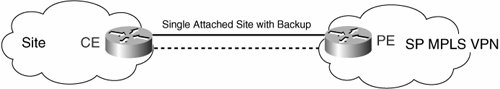
The alternative solution of using floating static routes over the dialup connection has been dropped, because the default routing is not allowed and would require configuring static routes matching the routes received dynamically. The BGP peers have their TCP session already established, and the BGP routes have already been exchanged. This is accomplished by using the eBGP multihop feature and the static routes directing both BGP sessions over the primary link, as shown in Example 4-7. Example 4-7. Configuring eBGP Multihop interface Loopback0 description ACME Management Loopback ip address CE-1-management-loopback 255.255.255.255 ! interface Loopback10 description ACME BGP Connectivity Loopback for SP ip address CE-1-peer-loopback 255.255.255.255 ! interface Serialx/y(.z) description ACME CE-PE (sub-)_interface ip unnumbered Loopback10 ip verify unicast reverse-path ! ! interface dialer0 ip unnumbered Loopback10 ip verify unicast reverse-path ! router EIGRP 100 redistribute bgp CE_AS subnets route-map BGP-to-EIGRP(VPN routes) network site_network_address mask passive-interface serial x/y(.z) passive-interface dialer0 no auto-summary ! router bgp 65535 no synchronization bgp log-neighbor-changes neighbor PE-1-peer-loopback remote-as PE-AS neighbor PE-1-peer-loopback password BGP#1-secret neighbor PE-1-peer-loopback ebgp-multihop 2 neighbor PE-1-peer-loopback update-source Loopback10 neighbor PE-1-peer-loopback timers 10 30 neighbor PE-1-peer-loopback advertisement-interval 15 neighbor PE-2-peer-loopback remote-as PE-AS neighbor PE-2-peer-loopback password BGP#2-secret neighbor PE-2-peer-loopback ebgp-multihop 3 neighbor PE-2-peer-loopback update-source Loopback10 neighbor PE-2-peer-loopback timers 10 30 neighbor PE-2-peer-loopback advertisement-interval 15 no auto-summary ! ip route PE-1-peer-loopback 255.255.255.255 Serialx/y(.z) ip route PE-2-peer-loopback 255.255.255.255 Serialx/y(.z) 201
|
When the primary link fails, the primary eBGP session goes down, and the dynamic routes between the backup eBGP peers are lost. There must be an additional floating static route on the CE side toward the service provider's backup edge router, PE-2. This route directs the outgoing packets to the dialer interface. As soon as the packets reach the dialer interface, the call is placed. When the PPP session is established, the router receiving the call installs a host route to the caller. The eBGP session runs uninterrupted over the dialup link. All previously received eBGP information is still valid. The next-hop attribute is the same, but the address now can be reached over the dialup link and not, as it used to be, over the primary link. Due to the pre-established session, the eBGP session continues uninterrupted if the dialup session is established within 30 seconds. The traffic is black-holed for the time the call is placed and the PPP session is established. The main difference is the backup scenario, when typically, much less bandwidth can be distributed between the available classes of traffic. The implementation should use the following guidelines: IP telephony (if/where used) should be rerouted to a fixed telephone network (such as the dedicated ISDN ports). Business-critical traffic is guaranteed a percentage of the bandwidth. Best-effort traffic is guaranteed a percentage of the bandwidth.
MLP can provide additional benefits: Medium SiteSingle CE Dual-Homed to a Single PE Solution characteristics for a single CE dual-homed to a single PE are as follows: Low cost Improved performance and availability by using identical parallel links Improved SLA and recovery capability Solution applicability: Site Type C
Suppose you have a limited budget or you cannot purchase a link with higher performance characteristics. You still can enhance performance by deploying multiple permanent connections between a single CE router on the Acme side and a single PE router on the service provider side. This setup is simplified by having EIGRP run between the CE and PE, thus removing the need to have BGP configured on the CE. Figure 4-19 provides an overview of the connection model. Figure 4-19. Single CE to Single PEDual Paths 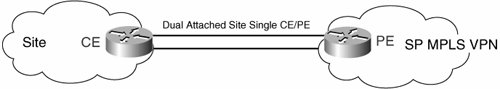
Load sharing can be performed depending on the CEF switching mode. The recommendation is to use Cisco default per-source-and-destination load balancing, where all packets with the same source/destination address pair are forwarded on the same link. Alternatively, an MLP bundle can be created, thus creating one logical link over which traffic is automatically load-shared. Example 4-8 shows this configuration. Example 4-8. Configuring a Single CE to a Single PE with Dual Paths interface Loopback0 description ACME Management Loopback ip address CE-1-management-loopback 255.255.255.255 ! interface Serialx/y(.z) description ACME CE-PE#1 (sub-)interface ip address 10.10.10.1 255.255.255.252 ip verify unicast reverse-path ! interface Serialx/z(.w) description ACME CE-PE#2 (sub-)interface ip address 10.10.10.6 255.255.255.252 ip verify unicast reverse-path ! Router EIGRP 100 Network 10.0.0.0 255.255.0.0 Distribute-list prefix OUTBOUND out Serialx/y(.z) Distribute-list prefix INBOUND in Serialx/y(.z) No auto-summary ! IP prefix-list OUTBOUND description permit local address blocks only IP prefix-list OUTBOUND seq 5 permit 10.1.1.0/24 ! IP prefix-list INBOUND description permit exact ACME ranges only IP prefix-list INBOUND seq 5 permit 0.0.0.0/0 IP prefix-list INBOUND seq 10 permit 10.48.0.0/13
|
In the single-CE setup, the link-level procedures should detect the link failure and place the interface in a down state. Recovery occurs via the EIGRP feasible successor, and all traffic is immediately forwarded on the remaining path. Large SiteDual-Homed (Dual CE, Dual PE) Dual-homed solution characteristics are as follows: High availability (emphasis on link and device protection) The site is a critical business site Solution applicability: Site Type B
As shown in Figure 4-20, the solution with multiple permanent connections between different routers in both the Acme network and the service provider network increases redundancy. It also covers the lost link and failures in the routers. The route selection policy is primary/backup, which is achieved by CE-2 and PE-2 assigning low local preference values on backup links, as shown in Example 4-9. Figure 4-20. Dual-CE-to-Dual-PE Connectivity 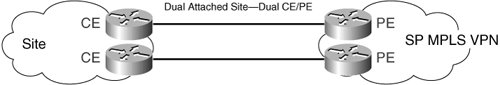
Example 4-9. Configuring Dual-CE-to-Dual-PE Connections ! CE-1 Configuration router EIGRP 1000 redistribute bgp CE_AS subnets route-map BGP-to-EIGRP !(VPN routes) network site_network_address wildcard_mask !For BGP connectivity include also loopback interfaces as host routes BGP routing interface Loopback0 description ACME Management Loopback ip address CE-1-management-loopback 255.255.255.255 ! interface Loopback10 description ACME BGP Connectivity Loopback for SP ip address CE-1-peer-loopback 255.255.255.255 ! interface Serialx/y(.z) description ACME CE-PE (sub-)interface ip unnumbered Loopback10 ! router bgp CE-AS !Site AS num no synchronization bgp log-neighbor-changes neighbor CE-2-peer-loopback remote-as CE-AS !iBGP session neighbor CE-2-peer-loopback update-source Loopback10 neighbor PE-1-peer-loopback remote-as PE-AS !SP AS num neighbor PE-1-peer-loopback password BGP#1-secret neighbor PE-1-peer-loopback ebgp-multihop 2 neighbor PE-1-peer-loopback update-source Loopback10 neighbor PE-1-peer-loopback timers 10 30 neighbor PE-1-peer-loopback advertisement-interval 15 aggregate-address site-aggregate mask summary-only ! ip route PE-1-peer-loopback 255.255.255.255 Serialx/y(.z) ____________________________________________________________________________ ! CE-2 Configuration interface Loopback0 description ACME Management Loopback ip address CE-2-management-loopback 255.255.255.255 ! interface Loopback10 description ACME BGP Connectivity Loopback for SP ip address CE-2-peer-loopback 255.255.255.255 ! interface Serialx/y(.z) description ACME CE-PE (sub-)interface ip unnumbered Loopback10 ! router bgp CE-AS !Site AS num no synchronization bgp log-neighbor-changes neighbor CE-1-peer-loopback remote-as CE-AS !iBGP session neighbor CE-1-peer-loopback update-source Loopback10 neighbor PE-2-peer-loopback remote-as PE-AS !SP AS num neighbor PE-2-peer-loopback password BGP#2-secret neighbor PE-2-peer-loopback ebgp-multihop 2 neighbor PE-2-peer-loopback update-source Loopback10 neighbor PE-2-peer-loopback timers 10 30 neighbor PE-2-peer-loopback advertisement-interval 15 neighbor PE-2-peer-loopback route-map LP-backup in aggregate-address site-aggregate mask summary-only ! ip route PE-2-peer-loopback 255.255.255.255 Serialx/y(.z) ! route-map LP-backup set local-preference 50 BGP route propagation router bgp CE-AS network site_prefix mask mask no auto-summary
|
In the event that the BGP configuration on the service provider PE assigns no particular preference to north or south connections, CE routers CE-1 and CE-2 can influence the return path selection by assigning multiexit discriminator (MED) values on outgoing updates, as shown in Example 4-10. Example 4-10. Configuring the MED to Influence Path Selection ! CE-1 Configuration ! Announcing MED for return path selection router bgp CE_AS neighbor PE-1-peer-loopback route-map MED-primary out ! route-map MED-primary permit 10 set metric 50 ____________________________________________________________________________ ! CE-2 Configuration ! Announcing MED for return path selection router bgp CE_AS neighbor PE-2-peer-loopback route-map MED-backup out ! route-map MED-backup permit 10 set metric 100
|
If the primary link or primary router fails, only one of the connections is lost. The other connection is still available. The third event type deals with breaking the connection between the CE routers in the Acme network. The following are the essential high-availability issues theoretically assessed with presumptive failures: Primary link failure With this type of failure, CE-1 takes up to the default holdtime (adjusted to 30 seconds) to detect that the PE-1 loopback address (the address used for the BGP peering) has gone. As soon as the lack of reachability has been identified, the router CE-1 removes all the routes from that neighbor, withdraws them from the CE-2 BGP table, and then must perform a path selection identifying CE-2 as a winner for the VPN routes. CE router failure scenario Router failure is detected either by the iBGP holdtime or by IGP removing the route to the peering loopback and the BGP scan process verifying the next-hop reachability. The first requires fine-tuning of the BGP scan process. The latter is considered more suitable by adjusting the BGP keepalive and holdtime timers. Failure inside the Acme network As soon as the link failure has been detected and the site iBGP session is torn down, both CE routers withdraw lost and start advertising reachable subnets. It is important that aggregation is turned off, or at least done architecturally adequately, so as not to attract the traffic to unreachable subnets.
Load Sharing Across Multiple Connections The objective that Acme wants to achieve at WAN speeds greater than E1/T1, for specific sites where the cost of a T3 or E3 is prohibitive, is load balancing. With this approach, the two access links actively share the traffic load from and to the branch. With the fallback port solution, one of the access links is the primary, and the other is the backup. The load sharing occurs on the two links so that the following things happen: The traffic from Acme toward the service provider is shared between the two access lines by configuring Hot Standby Router Protocol (HSRP) or Gateway Load Balancing Protocol (GLBP) on the two CE routers or, alternatively, on two routers or Layer 3 switches on the LAN, behind the CE. Load sharing from the service provider toward Acme is achieved by using iBGP multipath and eventually is combined with multipath load sharing for both eBGP and iBGP in an MPLS VPN feature on a particular PE router.
When HSRP is used to provide default gateway redundancy, the backup members of the peer relationship are idle, waiting for a failure event to occur for them to take over and actively forward traffic. GLBP protects data traffic from a failed router or circuit while allowing packet load sharing between a group of redundant CE routers, such as alternating between the multiple default gateways. HSRP may use multiple HSRP groups on a single interface to alternate between the multiple default gateways, but it is not optimal from a configuration or maintenance perspective. Very Large Site/Data CenterDual Service Provider MPLS VPN Dual service provider MPLS VPN solution characteristics are as follows: High availability (emphasis on link and device protection and even partial path protection) Data center sitelarger campus locations Business-critical Solution applicability: Site Type A
The multihomed site has two permanent links to different service providers. The links terminate in different edge routers in the Acme network. Otherwise, one of the major advantages, resilience to router failure, is lost. Figure 4-21 shows the design. Figure 4-21. Connecting to Dual Service Providers 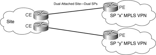
The assignment in this setup is to have one link as primary and the other as backup only. The site can use the local preference configuration to direct all outgoing traffic over the primary link. This configuration is no different from multiple connections running BGP to a single service provider. Controlling the distribution load of incoming traffic over the links is more difficult in the multihome scenario compared to multiple links to a single service provider. MED cannot be used because the updates are sent to two different autonomous systems. It is done with AS path prepending, extending the AS path attribute of local routes before sending the advertisement to the backup service provider. When the backup service provider receives the advertisement, the AS path is longer. This solution works in all cases where the default BGP route selection process (based on AS path length) is done, which is almost always the case. Example 4-11 provides an example of the required configuration actions. Example 4-11. Configuring the ASPrepending to Influence Path Selection Between Service Providers router EIGRP 100 redistribute bgp CE_AS subnets route-map BGP-to-OSPF !(VPN routes) network site_network_address wildcard_mask area area_num !For BGP connectivity also include loopback interfaces as host routes ____________________________________________________________________________ ! CE-1 Configuration interface Loopback0 description ACME Management Loopback ip address CE-1-management-loopback 255.255.255.255 ! interface Loopback10 description ACME BGP Connectivity Loopback for SP ip address CE-1-peer-loopback 255.255.255.255 ! interface Serialx/y(.z) description ACME CE-PE (sub-)interface ip unnumbered Loopback10 ! router bgp CE-AS !Site AS num no synchronization bgp log-neighbor-changes neighbor CE-2-peer-loopback remote-as CE-AS !iBGP session neighbor CE-2-peer-loopback update-source Loopback10 neighbor PE-1-peer-loopback remote-as PE-AS !SP AS num SP "X" neighbor PE-1-peer-loopback password BGP#1-secret neighbor PE-1-peer-loopback ebgp-multihop 2 neighbor PE-1-peer-loopback update-source Loopback10 neighbor PE-1-peer-loopback timers 10 30 neighbor PE-1-peer-loopback advertisement-interval 15 neighbor PE-1-peer-loopback filter-list 10 out ! ip route PE-1-peer-loopback 255.255.255.255 Serialx/y(.z) ip as-path access-list 10 permit ^$ BGP routing with SP x ____________________________________________________________________________ ! CE-2 Configuration interface Loopback0 description ACME Management Loopback ip address CE-2-management-loopback 255.255.255.255 ! interface Loopback10 description ACME BGP Connectivity Loopback for SP ip address CE-2-peer-loopback 255.255.255.255 ! interface Serialx/y(.z) description ACME CE-PE (sub-)interface ip unnumbered Loopback10 ! router bgp CE-AS !Site AS num no synchronization bgp log-neighbor-changes neighbor CE-1-peer-loopback remote-as CE-AS !iBGP session neighbor CE-1-peer-loopback update-source Loopback10 neighbor PE-2-peer-loopback remote-as PE-AS !SP AS num SP "Y" neighbor PE-2-peer-loopback password BGP#2-secret neighbor PE-2-peer-loopback ebgp-multihop 2 neighbor PE-2-peer-loopback update-source Loopback10 neighbor PE-2-peer-loopback timers 10 30 neighbor PE-2-peer-loopback advertisement-interval 15 neighbor PE-2-peer-loopback route-map LP-backup in neighbor PE-2-peer-loopback filter-list 10 out ! ip route PE-2-peer-loopback 255.255.255.255 Serialx/y(.z) ! route-map LP-backup set local-preference 50 ! ip as-path access-list 10 permit ^$ BGP route propagation router bgp CE-AS network site_prefix mask mask no auto-summary neighbor PE-2_peer_address route-map AS-prepend out ! route-map AS-prepend permit 10 set ip as-path CE_AS CE_AS
|
A dual-homed site with two CEs linked to two service providers creates challenges in the equalization of QoS design. Implementation must follow a consistent policy with both providers. QoS design and implementation on the backup path through service provider Y should follow these guidelines: Provide QoS guarantees on the CE-PE link from both ends. Try to enforce the same QoS policy that is used with service provider X to maintain consistency. If the other service provider's X SLA differs significantly from the service provider's Y policy, try to translate one of the service provider's policies into the policy of the other by doing one of the following: - Use marking as specified by the second service provider. - Provide a bandwidth guarantee to business-critical traffic. - Provide low latency to VoIP (IP telephony). - Reroute IP telephony to the public switched telephone network (PSTN) if a low-delay minimum-bandwidth guarantee is not possible under the SLA of the second service provider.
The high-availability requirements in this site type are assessed with the following objectives in mind: - The communication path at the physical layer needs to be protected against a single point of failure (node, ports, and link). - The Layer 3 network must be able to quickly converge in the event of route failure. The convergence of IGP and BGP contributes to the availability of IP.
Site Typifying Site Type A Failures The following are the essential high-availability issues theoretically assessed with presumptive failures: Link failure scenario CE-1 takes up to the default holdtime (adjusted to 30 seconds) to detect that the PE-1 loopback address has gone. The router CE-1 then removes all routes from that neighbor, withdraws them from the CE-2 BGP table, and performs a path selection identifying CE-2 as a winner for the VPN routes. CE router failure scenario Router failure is detected either by the iBGP holdtime or the IGP removing the route to the peering loopback and BGP scan process verifying the next-hop reachability. The first requires fine-tuning of the BGP scan process. The latter is considered more suitable by adjusting the BGP keepalive and holdtime timers. Failure inside ACME network As soon as the link failure has been detected and the site iBGP session is torn down, both CE routers withdraw lost and start advertising reachable subnets. It is important that aggregation is turned off, or at least done architecturally adequately, so as not to attract the traffic to unreachable subnets.
Solutions Assessment Table 4-2 summarizes the test results to prove the presented connectivity concepts for Site Type A sites. As stated, high performance and high availability are the key factors when designing WAN for this site type; therefore, the testing is performed with the intention to verify the ability of these features for this site type. Table 4-2. Sample Testing MatrixTest | Test Observation with Regard to Solution | Pass/Fail/Comments |
|---|
Failoverservice provider X Failoverservice provider Y | | | BGP routing | | | BGP load sharing | | | BGP convergence | | | Link failure | | | CE router failure | | | Simulated PE failure | | | Failure inside the Acme network | | | Load performance on the secondary path during an outage | | | Load balancing (internal) end access point access | | | Real-time traffic (voice/video) performance during failure | | | Recovery time tracking | | | IGP routing recovery | | | IGP convergence | | |
|