Mapping Requirements Directly to Design and Code
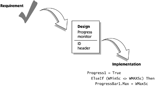
| Fortunately, for some percentage of our requirements, we can design the software so that it is relatively easy to follow our requirements into design and then into code. This also means that we can test a significant portion of our code, using a requirement-to-module test, since there will be a reasonable degree of correlation between the statement of a requirement and the code that implements it. For example, it's probably fairly straightforward to find, inspect, and validate the code that fulfills the requirement "Support up to an eight-digit floating-point input parameter," or "Indicate compilation progress to the user ," as we can see in Figure 25-1. Depending on the type of system we are building, this approach may work for a substantial portion of our code, so the requirements-to-design-to-implementation process is not so difficult in these cases. Figure 25-1. From requirements to design to implementation ”a direct mapping The Orthogonality Problem
Object OrientationIn many ways, this problem of orthogonality ”a lack of direct relationship between requirements reflecting the problem space and the code we implemented ”was substantially improved with the advent of object-oriented (OO) technology. In applying OO concepts, we tended to build code entities that were a better match to the problem domain, and we discovered that an improved degree of robustness resulted. This was due not only to the OO principles of abstraction, information hiding, inheritance, and so on but also to the fact that the real-world entities simply changed less often than the transactions and the data on which we formerly designed our system. Therefore, our code changed less often, too. (For example, people still get paychecks today, just as they did 40 years ago, but in many cases the form of delivery ”electronic versus paper ”has changed dramatically.) With OO technology, we did start to find engine objects and paycheck objects in the code, and we used this to good advantage to decrease the degree of orthogonality in requirements verification. We could look at the requirements for "paycheck stub" and see whether the implied operations and attributes were supported in the design model. However, we must be careful because a purposeful attempt to provide a one-to-one mapping from requirements to code can lead to a very non-OO architecture, one that is functionally organized. The basic principles of OO technology drive the designer to describe a small number of mechanisms that satisfy the key requirements of the system, resulting in a set of classes that collaborate and yield behavior that's bigger than the sum of its parts . This "bigger behavior" is intended to provide a more robust, more extensible design that can deliver the current and, ideally , future requirements in the aggregate , but it is not a one-to-one mapping from requirements. Therefore, even with OO technology, some degree of orthogonality with requirements will always, and should always, remain . The Use Case as a RequirementAs we mentioned earlier, the "itemized" nature of the requirements can further compound the problem of orthogonality. Each requirement by itself may not present a huge problem, but it makes it difficult to look at system behavior in the aggregate to see whether it does all the right things and in the right sequence. How could we examine the system to determine whether requirement 3 ("Display progress bar") immediately followed requirement 7 ("During compilation, the algorithm is . . .")?
Managing the TransitionAlthough, with OO methods and use cases, we haven't solved the problem of orthogonality, we do have a number of existing assets and a few new techniques that can help us deal with the problem. If we can use these assets to increase the parallels between requirements and code, it seems likely that we can use our understanding of the requirements to more logically drive the design of the system. In so doing, it should also be easier to translate between these dissimilar worlds , to improve the design of the system, and to improve the overall quality of the system that results. Before we do so, however, we need to make a small digression into the world of modeling and software architecture. Modeling Software SystemsNontrivial software systems today are extraordinarily complex undertakings. It is common to find systems and applications that are composed of millions of lines of code. These systems or applications may, in turn , be embedded in other systems that also have an extraordinary complexity in their own right, not to mention the complex interactions that may occur between the systems. We take it as a given that no one person or even group of persons can possibly understand the details of each of these systems and their planned interactions. In the face of this complexity and to keep our wits about us, a useful technique is to abstract the system into a simplified model , removing the minutia of the system in order to view a more comprehensible version. The purpose of modeling is to simplify the details down to an understandable "essence" but not to oversimplify to the point that the model does not adequately represent the real system. In this way, we can think about the system without being buried in the details. Selection of the model is an important issue. We want the model to help us understand the system in the proper way, but we don't want the model to mislead us because of errors or abstractions. You've undoubtedly seen pictures of drawings and machines that helped the early philosophers , astronomers, and mathematicians understand the workings of the solar system. Many of these models, based on a geocentric view of the solar system with Earth at the center of the universe, thus led to many blind alleys and incorrect theories . Only when sun-centered, or heliocentric, models were proposed did a better understanding of our solar system emerge.
Models provide a powerful way to reason about a complex problem and to derive useful insights. However, we must be aware that the model is not the reality . We must continually check and assure ourselves that the model has not led us astray.
Many different aspects of a system can be modeled. If you are interested in application concurrency, you may model that. If you are interested in the system's logical structure, you may model that. In addition, these models need to interact in some way, and that aspect too can be modeled . Each of these mechanisms contributes to our understanding of the system in the aggregate, and taken together they allow us to consider the system architecture in the whole. The Architecture of Software SystemsAccording to Shaw and Garlan [1996], software architecture involves the
According to Kruchten [1999], we use architecture to help us:
Architecture becomes the tool by which decisions are made about what and how the system will be built. In many projects, we know at the start how we are going to put the pieces together because we, or others, have developed such systems before. The easy starting decisions are reflected in the dominant architecture notion, which is just a fancy way to say that "everyone knows how to build a payroll system." Dominant architecture helps us kick-start the decision process and minimizes risk through the reuse of pieces of a successful solution. If you're going to build a payroll system, it would be silly to start from scratch and invent the entire concept of FICA, check writing, medical deductions, and so on. Start by looking at models of existing systems, and use them to prompt your thinking.
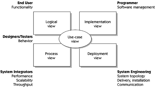
Different groups of stakeholders need to consider your architectural models and will want to view the proposed architecture from different perspectives. The parallel to a "building a house" metaphor holds. You'd want to have views of the house that were suitable for the framers, the roofers, the electricians, the plumbers, and so on. It's all the same house, but our view of it may differ , depending on the need. The "4+1" View of ArchitectureThere is usually a small set of common needs for viewing the system architecture. The views that best illustrate these needs are discussed by Kruchten [1995] as the "4+1" view shown in Figure 25-2. The figure identifies a number of stakeholders (programmers, managers, users) and positions them near the types of views they would normally need to consider.
Figure 25-2. The 4+1 architectural view The Role of the Use-Case Model in Architecture
For example, the HOLIS use case Initiate Emergency Sequence would impact the design of the system in each of the four views as follows .
|
EAN: N/A
Pages: 257
- Chapter I e-Search: A Conceptual Framework of Online Consumer Behavior
- Chapter III Two Models of Online Patronage: Why Do Consumers Shop on the Internet?
- Chapter V Consumer Complaint Behavior in the Online Environment
- Chapter VI Web Site Quality and Usability in E-Commerce
- Chapter XII Web Design and E-Commerce

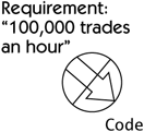
 However, when it comes to such requirements as "The system shall handle up to 100,000 trades an hour " or a use-case step like "The user can edit each of the highlighted fields in accordance with user privileges that have been established by the system administrator," things get a little trickier. In these cases, there is little correlation between the requirement and the design and implementation; they are