3D: A Whole New World
| Few features in Illustrator are as fun to use as the 3D effect. You might want to clear your calendar for a few days so that you have time to explore all of the cool functionality you're about to discover.
However, before you tie a bungee cord to your ankles and jump into the spectacular world of 3D, it's important to realize just what the 3D effect in Illustrator is capable of and what its limitations are. In this way, you'll get a better idea of what you can realistically expect from the 3D effect.
Many different uses come to mind when we think about using the 3D effect in Illustrator. Drawing boxes and bottles for product packaging concepts and mockups, and text headlines or logos with added dimension, are some examples. However, as you will see, the 3D effect in Illustrator can also serve in an extremely creative fashion. As you explore the different capabilities of the 3D effects, try to envision how you might use them to create illustrations or design elements. We will help by offering examples along the way, providing a spark to get your creative juices flowing. Looking Inside the 3D EffectThe 3D feature in Illustrator is extremely deep and comprises four different components, each serving a different purpose:
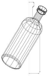
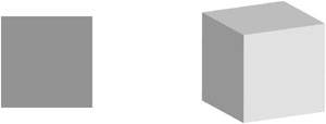
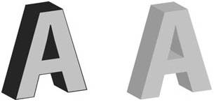
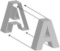
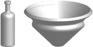
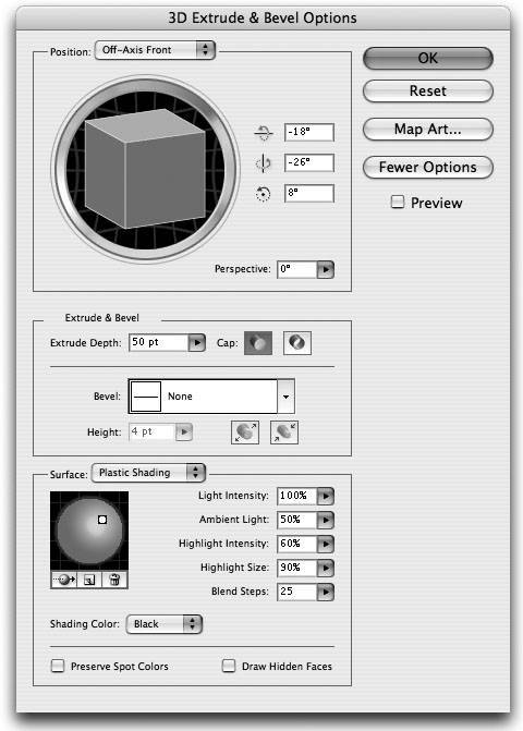
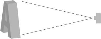
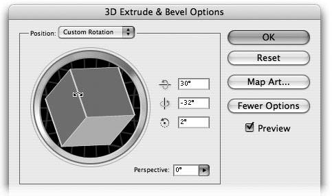
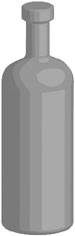
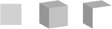
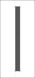
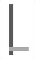
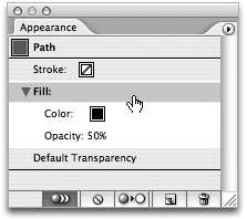
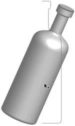
Naturally, each of these four components is a full-blown feature and requires its own detailed instructions. However, before we get to each of these, you need to learn some general information about how the 3D effect in Illustrator works. Fills and Strokes and the 3D EffectIn order to harness the depth of the 3D effect in Illustrator, you have to learn what makes the effect tick. The way in which you create and edit your vector shape has an effect on how the 3D settings are applied to that shape. For example, take two identical shapes: one has a stroke applied, the second has the stroke set to None (Figure 7.12). When the same 3D Extrude effect is applied to both objects, each assumes a different appearance (Figure 7.13). Figure 7.12. These shapes are identical with the exception of the 1-point stroke applied to the one on the left. Figure 7.13. The extruded area of the shape on the left takes on the appearance of the object's stroke attribute whereas the shape on the right uses the appearance of the fill. Here's what happens: right before Illustrator applies 3D to an object, the effect breaks apart the elements internally and applies the 3D effect to each of the elements. When you have an object that has just a fill applied, the fill itself is extruded, and the extruded areas are shaded in the same color as the fill. However, if a stroke is applied to the object as well, Illustrator extrudes the fill and the stroke, and the appearance of the extruded areas show the stroke color, not the fill color. In fact, when you have a stroke applied, Illustrator is really extruding two separate objectsthe fill and the stroke around it (Figure 7.14). If you change the fill setting to None, you'll be able to see right through the middle of the object, because then Illustrator is only extruding a stroke, and not a fill (Figure 7.15). Figure 7.14. When an object with a fill and a stroke is extruded, you can think of the stroke as a slipcase for the fill. Figure 7.15. When no fill is present, Illustrator only extrudes the stroke, resulting in a hollow shape. There's another side effect to applying a 3D effect to an object with a stroke applied that pertains to artwork mapping. You already know that artwork mapping allows you to apply 2D art to the surface of any 3D object. We'll discuss exactly how artwork mapping is applied later in the chapter, but one of the main things you'll need to do with artwork mapping is choose on which surface of a 3D object you want your mapped artwork to appear (you can apply artwork to multiple surfaces as you will learn later). When you apply an Extrude effect to a rectangle with just a fill, the result is a 3D object that has six surfaces. However, if you apply a stroke to that rectangle, the result is a 3D object with 24 surfaces. This is because Illustrator counts all of the surfaces generated by the fill as well as those generated by the stroke (the surfaces that appear along the inside of the stroke, even though they are not visible, are still counted as surfaces). Because of this, it can be difficult to choose from the numerous surfaces to figure out which one you want the artwork mapped onto. Of course, there are times when you will want to apply a stroke to an object with a 3D effect, such as with extruded text. By adding a stroke to your Text object, you can create text that is filled with one color but that is extruded using a different color (Figure 7.16). Chances are good that you won't be mapping artwork onto your text, so this example is a good use of a stroke on a 3D object. Figure 7.16. When extruding text, adding a stroke allows you to create a powerful contrast to the extruded effect. In review, feel free to use strokes on your objects if you need them to get the look you are trying to achieve. However, be aware that adding strokes slows performance and makes artwork mapping a confusing process because of all of the extra surfaces. Editing a 3D EffectBecause 3D is a Live Effect in Illustrator, you can make edits to the original vector shape on the artboard and the 3D effect updates accordingly. You can also change the color of the object and the 3D effect automatically updates as well, including the shading of the object. You know that you can double-click an effect listed in the Appearance palette to edit 3D effects that have already been applied to artwork. However, it's important to remember that the artwork that appears on your artboard after you've applied a 3D effect is 2D. If you want to rotate a 3D object, don't do it on the artboard using the usual transformation tools. Rather, double-click the 3D effect in the Appearance palette and rotate the object in the 3D Options dialog. Changing the artwork on the artboard produces undesirable results (Figure 7.17). For more information on transforming artwork that has Live Effects applied, see the sidebar, "Transforming Objects with Effects," later in this chapter. Figure 7.17. What started out a wine bottle (left) may not appear the same when you rotate it on the artboard (right). To rotate the bottle in 3D, you have to edit the 3D effect. Applying the 3D Extrude & Bevel EffectNow that you generally understand how the 3D effect works in Illustrator, you will learn how to apply the effect, determine all of its settings, and perhaps most importantly, study a few practical examples of how you might use such an effect. As we defined earlier, the Extrude & Bevel effect adds depth to an object. To apply this effect, select a vector object on the artboard and choose Effect > 3D > Extrude & Bevel to open the Extrude & Bevel Options dialog. First, check the Preview button in the dialog so that you can see what the 3D effect looks like as you adjust the settings. If you don't have a large screen, it helps to position your artwork on one side of the screen before you apply the effect, and place the Extrude & Bevel options dialog (when it opens) to the other side so that you can see the preview on the artboard (Figure 7.18). Figure 7.18. Especially on smaller screens, it helps to keep your art positioned on the left side of the screen so that you have room to preview the art while you make adjustments in the 3D Extrude & Bevel Options dialog.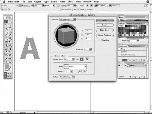 At this point, you are ready to begin experimenting with the different settings found in the dialog. To make the feature more approachable, Adobe splits the dialog into two parts. By default, only half of the settings appear in the dialog. By clicking the More Options button, you can expand the dialog to show all of the settings that we will be talking about here (Figure 7.19, next page). Figure 7.19. By clicking the More Options button, you can expand the 3D Extrude & Bevel Options dialog to see all of the available settings.
The 3D Extrude & Bevel Options dialog is divided into three sectionsPosition, Extrude & Bevel, and Surfaceeach covering a different aspect of 3D.
Specifying the Position SettingsThe Position section of the 3D Extrude & Bevel Options dialog allows you to rotate your object within a 3D space (on its X, Y, and Z axes) in order to control the view of your object. In 3D applications, the term camera is used to define the view of the object (as if you were seeing the object through the lens of a camera; Figure 7.20). Figure 7.20. The Position setting allows you to rotate the view of an object, as if you were looking at the object through the lens of a camera. The most distinctive element in the 3D Extrude and Bevel Options dialog is what Adobe engineers affectionately call the "track cube"a visual representation of the position of your 3D object. The track cube acts much like a trackball, only it isn't round (hence, the name). To adjust the position of your 3D object, simply click and drag on the track cube. As you adjust the position, a wireframe preview appears on your screen, indicating how the object will appear (Figure 7.21). When you release the mouse, a full preview, with shading, appears. Figure 7.21. As you adjust the track cube, a wireframe preview shows you what your art will look like.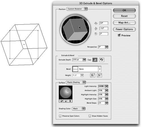 The track cube is more than just fun to play withit also has some pretty cool functionality. The sides of the cube are shaded in different colors to help you easily identify the position of your object: the front side is shaded blue and the back is a very dark gray; the top and bottom are light gray; and the left and right sides are a neutral gray.
In addition, as you move your mouse over the edges of each side, you'll notice the edges highlight in red, green, and blue (Figure 7.22). Clicking and dragging on these highlighted edges constrains the object to rotate only along one axis, making it easier to control the position of your object. Holding the Shift key while dragging the track cube simulates a rotation of the floor beneath the object, and dragging on the outer ring of the track cube constrains the rotation in the other direction. Figure 7.22. Moving your mouse over the edges of the track cube allows you to make adjustments to one axis at a time. Along the right side of the track cube are three values that represent the three axes that a 3D object needs. Each axis can have a value of 180 to 180 degrees (for a total of 360). You'll notice that the highlighted colored track cube edges match the color shown for the icon in each of these three axes.
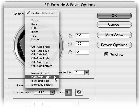
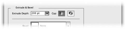
Appearing directly above the track cube is a pop-up menu that contains a list of preset positions from which you can choose. Choosing one of these presets positions your object in a variety of different views. Unfortunately, you cannot define your own presets here, but they can make it easy to apply consistent views throughout your artwork (Figure 7.23). Figure 7.23. Choosing one of Illustrator's preset position settings can make it easy to position several objects with the same view, such as when you are creating isometric art. Last, you can add perspective to your object by dragging the Perspective slider. This setting mimics the natural lens distortion that occurs if you move your object closer to the lens of the camera (Figure 7.24). If you hold the Shift key while adjusting the slider, you will see your preview update in real time (system performance permitting). Figure 7.24. Adjusting the Perspective slider can add natural distortion to your object.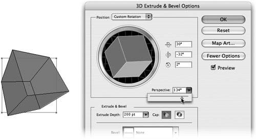 You will notice that as you increase the Perspective value, your 3D object becomes darker. Think about it: as you move an object closer to the lens of a camera, less light is available to reflect off the object and the object becomes darker. Soon we'll talk about surface and lighting options, which we can use to adjust the lighting of the object. Specifying the Extrude & Bevel SettingsThe Extrude & Bevel section of the 3D Extrude & Bevel Options dialog allows you to define the depth of your object as well as how the edges of your 3D object appear, also known as the bevel. To adjust the depth of your object, enter a numeric value, click and drag the Extrude Depth slider, or enter a value in the field. If you hold the Shift key while adjusting the slider, you can preview the extrude depth setting in real time. The values used for the extrude depth settings are shown in points, although you can specify values in inches or any other format, and Illustrator will do the conversion for you. You can specify an extrude depth up to 2000 points (a tad more than 27.75 inches). Speaking of measurements, when you're trying to create package mockups, it's always a good idea to work at actual size or in scale to ensure that your 3D object is proportioned correctly. By default, Illustrator creates closed extruded objects from filled paths. However, you can also specify the extrude setting you want to use so it shows only the extrusion and not the actual face or back of the shape. Toggling between the two cap settings allows you to control whether your objects have a solid or a hollow appearance (Figure 7.25). Figure 7.25. The Cap setting appears as two icons. The shaded icon indicates the selected setting. When you extrude an object, you can almost think of copying your object, offsetting the copy from the original, and then connecting the two with straight lines (Figure 7.26). A bevel is defined when you connect the two shapes with a line that is not straight, and therefore, the extrusion follows the direction of the line (Figure 7.27). Figure 7.26. A normal extrude is created by connecting the front and back faces of an object with a straight line. Figure 7.27. An extrude with a bevel is created by connecting the front and back faces of an object with a line that is not straight.
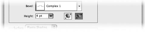
Illustrator provides a list of ten different bevels, which you can choose from the Bevel pop-up menu (see the sidebar, "Defining Your Own Bevels"). The Height setting controls the size of the bevel. You can also choose whether you want the bevel to be subtracted from the size of the original shape, or if you want it added to the shape (Figure 7.28). Figure 7.28. Toggling between the Bevel Extent In and Bevel Extent Out options can have an effect on the overall size of your object.
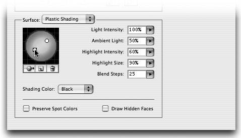
Specifying the Surface SettingsThe first two settings, Position and Extrude & Bevel, define the actual geometry of the shape. The Surface section of the 3D Extrude & Bevel Options dialog enables you to control the appearance of the surface of your object. This includes the type of shading used, as well as indicating how light will interact with the object. If you talk to a photographer, he will tell you that above all, lighting is of utmost importance. As you'll find out, the same is true with 3D. You may have noticed that when you first checked the Preview button to see what your 3D effect looks like on the artboard, the object changed somewhat in color. For example, if your original object was filled with a bright yellow color, the object might now show a darker muddy yellow color instead. By default, 3D objects in Illustrator are rendered with a single light source from the upper right and are shaded by adding black to the original fill color, giving that darker appearance. From the Surface pop-up menu, you can choose from one of four different options to specify the type of surface you want your 3D object to have. The surface type that you choose also defines what other surface settings are available for your object, and ultimately how you see the final 3D object (Figure 7.29). The four surface settings are as follows:
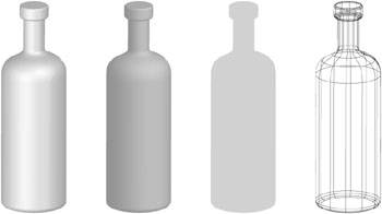
Figure 7.29. From left to right, this art demonstrates examples of Plastic Shading, Diffuse Shading, No Shading, and Wireframe. On the left side of the Surface section of the dialog is a lighting sphere, which is used to control how light is directed at your 3D object. A small white circle indicates the light source, and you can drag it to control the direction of the light (Figure 7.30). As you move the light source, you can hold the Shift key to see the shading preview in real time. To add additional lights (you can add up to 30 of them), click the New Light icon that appears directly beneath the sphere, and to delete a selected light, click the Delete Light icon. You can also send lights behind an object by clicking the Move selected light to back of object icon. Figure 7.30. You can drag lights across the sphere to adjust the shading of the 3D object. To the right of the lighting sphere, there are five settings that define how the surface and the lighting interact with each other. Depending on the Surface option that you select, you may see all or only some of these options:
Illustrator also offers a pop-up menu from which you can choose a shading color. By default, Illustrator adds black to your object to simulate shading; however, you can choose Other and pick any color from the color picker or from existing swatches in your document to use as a shading color instead. If you use colors other than black for shading, the result will be as if you were casting a colored light on your object.
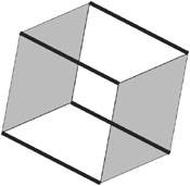
Using Spot Colors in 3D ObjectsIf your object is filled with a spot color, and if you use black or a spot color as your shade color, choosing the Preserve Spot Colors option causes the overprint function to be utilized when you're creating blends for shading. The result is an object that prints and separates correctly using the spot colors. You may have to view your file with Overprint Preview turned on if you want to preview the art correctly on your screen. Illustrator and 3D GeometryAlthough it's true that the 3D feature in Illustrator is doing real 3D rendering in a 3D world, that's only true while the 3D effect dialog is open on your screen. Once you click OK, Illustrator creates a 2D representation of that graphic and displays it on your artboard (Illustrator's artboard is only 2D). If you want to view your object differently, you can always edit the effect by double-clicking it in the Appearance palette, at which time the dialog opens. At this point, you're in the 3D world again, where you can rotate the object in space and then press OK to create the 2D representation that is displayed on the artboard. Because Illustrator knows that the end result will be a 2D drawing, it saves processing time by only calculating and drawing the visible sides of an object. For example, if you were to create a rectangle and extrude it to create a cube, at any one time, you would only be able to view three of the six surfaces. You can see this for yourself by following a few quick steps to expand the appearance of a 3D object.
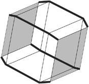
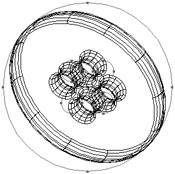
There are times however, when you might want the full geometry of the 3D object rendered. For example, if you wanted to expand the cube you created to modify the 3D object on your own, you might want all of the surfaces to be available. For this reason, Illustrator includes an option called Draw Hidden Faces, which forces Illustrator to render the entire object, even the surfaces that aren't visible. Again, you can easily see the difference by following a few short steps using the Draw Hidden Faces option.
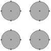
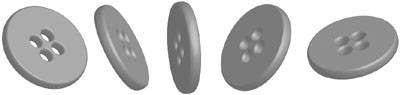
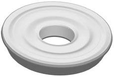
As you learn more about the 3D effect, you'll find that there are other uses for the Draw Hidden Faces option as well. Creating a Photorealistic ButtonNow that you've learned the different settings for the 3D Extrude & Bevel effect, it's time to put that knowledge to good use. In this exercise, you will create a realistic button (the kind you would find sewn to a shirt), but don't worryyou don't need to know how to draw. Illustrator's 3D effect allows you to create this button easily by drawing simple shapes.
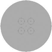
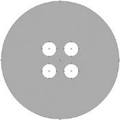
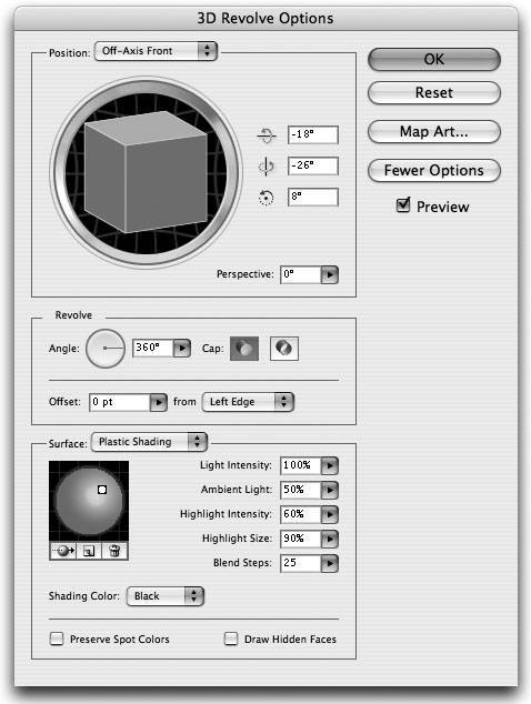
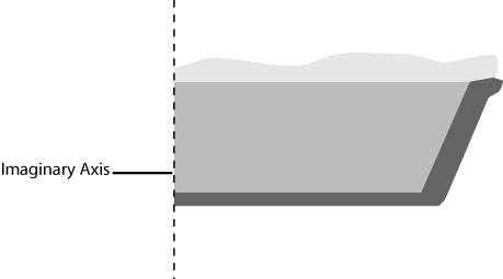
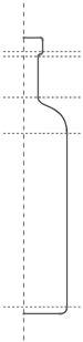
Because 3D is applied as a Live Effect, you can change the color of the button simply by applying a different fill color to the shape. Additionally, you can double-click the effect in the Appearance palette to edit the effect and change the position of the button so that you can view it from virtually any angle (Figure 7.38). This is a great example of how you can use the 3D Extrude & Bevel effect in a creative way, allowing you to easily create design elements that might otherwise be difficult to draw. Figure 7.38. Once you've created the button in 3D, you can change its position so that you can view it from any angle. Applying the 3D Revolve EffectAs we briefly discussed earlier, the Revolve effect adds dimension to an object by rotating a 2D shape around an axis. To apply this effect, select a vector object on the artboard and choose Effect > 3D > Revolve to open the 3D Revolve Options dialog. First, check the Preview button in the dialog so that you can see what the 3D effect looks like as you adjust the settings. If you don't have a large screen, it helps to position your artwork on one side of the screen before you apply the effect, and to position the Revolve options dialog, when it opens, to the other side so that you can see the preview on the artboard. At this point, you are ready to begin experimenting with the different settings found in the dialog. As with the 3D Extrude & Bevel dialog, the 3D Revolve dialog has a More Options button, which expands the dialog to reveal all of the settings for the feature (Figure 7.39). Figure 7.39. Similar to the 3D Extrude & Bevel Options dialog, you can expand the 3D Revolve Options dialog to reveal more options as well. The fully expanded 3D Revolve Options dialog is divided into three sections: Position, Revolve, and Surface. The Position and Surface sections are identical to those found in the 3D Extrude & Bevel Options dialog, so we will focus on just the Revolve section here. Specifying the Revolve SettingsThe Revolve section of the 3D Revolve Options dialog allows you to define exactly how your object will appear when revolved around an axis. Before we discuss the settings themselves, it's important that you first understand how the 3D Revolve effect in Illustrator works. By default, the left-most point of the selected object becomes a vertical axis for the effect. An object can only have one axis and the axis is always vertical. Unfortunately, Illustrator doesn't preview or show you this axis onscreen, so think of it as an imaginary axis (Figure 7.40). Figure 7.40. By default, Illustrator's 3D Revolve effect uses the left-most side of an object as the vertical axis. Now that you understand how revolve works, you can learn how to use the remaining settings in the Revolve section of the dialog:
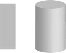
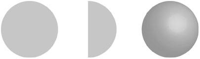
Drawing a SphereNow that you've learned how the 3D Revolve effect works, you can learn how to create a simple objecta sphere (Figure 7.44). Figure 7.44. From left to right: creating a circle; deleting an anchor point to create a semicircle; and applying a 3D Revolve effect to create a sphere.
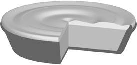
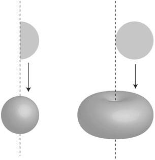
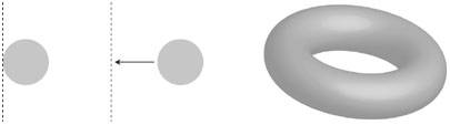
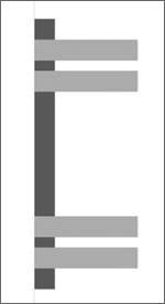
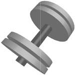
The most important part of this exercise was deleting half of the circle. As we mentioned earlier, the left side of the object is what defines the invisible axis on which the object revolves. If you were to apply a 3D Revolve effect to a full circle, the result would be quite different (Figure 7.45). In fact, applying the 3D Revolve effect with an offset value specified would produce a donut shape, which is nice, but not what you intended (Figure 7.46). Getting hungry? Figure 7.45. It's important to pay attention to where the vertical axis is. With a semicircle (left), the vertical axis is positioned to create a sphere. With a full circle (right), though, the vertical axis is positioned to create a donut shape. Figure 7.46. Starting with a full circle (left) and specifying an offset for the axis (center) results in a donut shape (right). Drawing an Exercise BarbellTo get your mind off of food for a while, here's a little mental exercise that uses the 3D Revolve effect and incorporates the use of groupsan extremely important aspect of creating complex 3D shapes (see sidebar titled "The Importance of Applying 3D Effects to Groups" later in this chapter). In this example, you will create a group of shapes that will result in a great-looking barbell. Again, you don't want to focus on drawing a barbell as much as trying to build the shapes that will eventually help Illustrator's 3D feature draw it for you (it's always preferable to let the computer do all the hard work while you relax and rack up the billable hours). To create the barbell, perform the following steps:
The most important part of this exercise is to try and visualize where the invisible axis is. When you think of a barbell, you may think of it as you normally see itlying on the ground, in a horizontal format. Because Illustrator's Revolve effect always uses a vertical axis, you had to think of the barbell as standing on its side. Once it's created, you can use the track cube to rotate it into any position or orientation that you need.
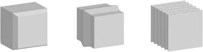
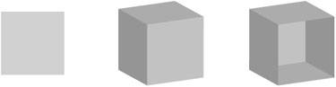
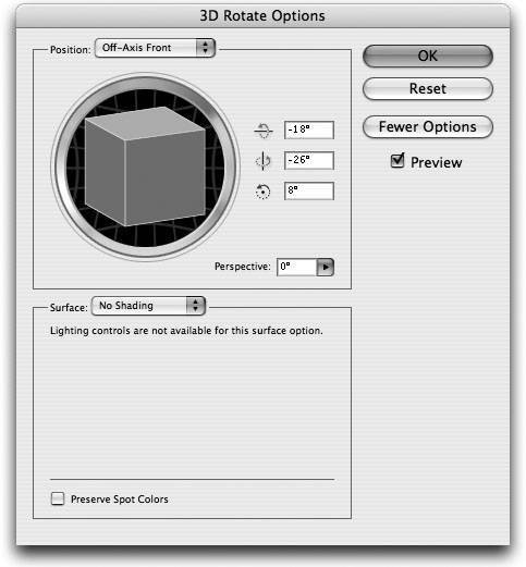
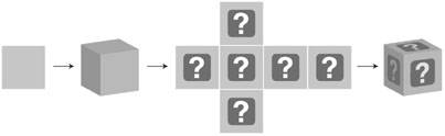
Hopefully, these examples that you've tried so far will help fuel your creativity and give you the information you need to create complex 3D objects on your own. Applying the 3D Rotate EffectThe Revolve effect doesn't add dimension to an object. Rather, the effect allows you to position a 2D object in a 3D space. Basically, the 3D Rotate effect does the same as the 3D Extrude effect without adding any depth. To apply this effect, select a vector object on the artboard and choose Effect > 3D Rotate to open the 3D Rotate Options dialog. The settings found with this 3D effect are identical to those we've already discussed, although take note that the 3D Rotate effect is limited to far fewer options (Figure 7.52). Most notably, you can only specify the Diffuse Shading or No Shading option, there are no bevels, and there is no support for artwork mapping (which we'll cover next). Figure 7.52. Although there is a More Options button in the 3D Rotate Options dialog, you'll find it doesn't really offer that much. The 3D Rotate effect can be useful for applying distortion to artwork, such as making artwork look as if it's mounted on a billboard. It also enables you to add perspective to your artwork as well. Mapping Artwork to 3D SurfacesOne of the things that really sets Illustrator's 3D effect apart from the 3D features found in other vector applications is the ability to map 2D artwork onto the surface of a 3D object. This method of combining 2D and 3D graphics is called artwork mapping. So that you understand what artwork mapping really is, let's take a closer look at a 3D cube. As we discussed earlier in the chapter, a 3D cube has six surfaces. Each of these surfaces is treated as a separate entity, and artwork mapping is the process of placing artwork onto these surfaces (Figure 7.53). Figure 7.53. Starting with a normal square, a 3D Extrude effect produces a cube with six surfaces. When 2D artwork is placed onto these surfaces, the result is a 3D object with artwork mapping. There are a few things you have to know before you get started with artwork mapping:
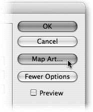
Specifying Mapped ArtworkIn order to map artwork onto the surface of a 3D object, you must first apply a 3D effect to an object. Then, from either the 3D Extrude & Bevel Options dialog or the 3D Revolve Options dialog, click the Map Art button to bring up the Map Art dialog (Figure 7.56). If the Preview option in the resulting Map Art dialog isn't checked, go ahead and turn it on so that you can see what your mapped artwork will look like as you make adjustments to it. Figure 7.56. The Map Art button appears directly below the Cancel button in the 3D Revolve or 3D Extrude & Bevel Options dialog. Before you can map art onto your object, you have to choose onto which surface of the object you want to place your artwork. At the top of the Map Art dialog, there are buttons with arrows that allow you to navigate or step through each of the surfaces of your object. As you step through each surface, Illustrator displays the selected surface in the center of the Map Art dialog. In addition, Illustrator tries to help you identify the selected surface by highlighting it with a red outline on the artboard (Figure 7.57, next page). Depending on the color of your object, this red outline could be helpful, or it could be barely visible. Figure 7.57. Illustrator tries to help you identify each of the surfaces, although the alignment of the red outlines isn't always perfect on the artboard. The surface that appears in the Map Art dialog is shaped as if it is laid flat. You'll notice as you step through the different surfaces on your object that some show a light gray background whereas others show a dark gray background. Some surfaces may even show a background that is dark gray only in certain areas. This is Illustrator's way of letting you know which surfaces, or which parts of a surface, are not visible, or are hidden from view (Figure 7.58). As you would expect, if you choose to use the track cube to view your object from a different perspective, the shaded surface areas in the Map Art dialog updates accordingly. Figure 7.58. This surface, which is the section that connects the body and neck of the wine bottle, has both shaded and non-shaded sections. Once you've chosen the surface you want to map art onto, use the Symbol pop-up menu to choose a symbol. The selected symbol appears on the surface area in the Map Art dialog with a bounding box. You can drag the symbol to position it to your liking on the surface, and you can also drag on the handles to resize it (Figure 7.59). As you adjust the position of the symbol, you will see the preview update on the actual 3D object on the artboard. Alternatively, you can use the Scale to Fit button at the bottom of the Map Art dialog to have Illustrator resize your symbol to fit to the surface, although it does so non-proportionally. Figure 7.59. You can move and rotate a symbol so that it appears as you need it to on the surface of the object.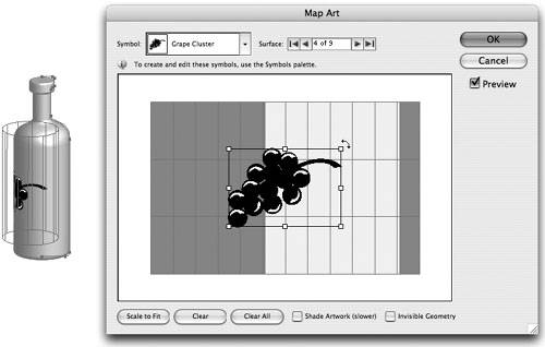 Once you're happy with the size and position of your symbol on the selected surface, use the arrows at the top of the dialog to navigate to another side to map additional symbols, as needed. At any time, you can click the Clear button to remove a symbol from a selected surface, or you can click the Clear All button to remove symbols from all surfaces at once.
By default, Illustrator only calculates shading and lighting for the actual surface of a 3D object, and not artwork that is mapped to a 3D surface. Illustrator does this purely for performance reasons. We mentioned earlier that Illustrator uses blends to calculate shading, and breaking down intricately mapped artwork and shading each element with blends takes quite a bit of processing. However, in order to get a realistic appearance, most likely you will want your mapped artwork to be shaded, even if it takes a bit longer to do so. Checking the Shade Artwork (slower) check box forces Illustrator to shade both the surface of your object and the mapped artwork as well. This setting applies to the entire object, and you don't need to turn it on for each individual surface.
The last setting in the Map Art dialog is a check box marked Invisible Geometry, which is a slightly technical term. When this option is turned on, Illustrator hides the actual 3D object on your artboard and displays just the mapped artwork. The result is a symbol that appears to float in space. A good example of when this setting might be useful is when you want to make text appear as if it were wrapped around a sphere (Figure 7.60). Figure 7.60. You can map artwork around a sphere (left), and by using the Invisible Geometry option in the Map Art dialog, you can hide the sphere leaving just the artwork (right). When you're happy with your artwork mapping settings, click OK to accept the settings in the Map Art dialog and then click OK to close the 3D dialog. What If . . . You Add Transparency to 3D?Throughout this entire book, you've seen how transparency is integrated into Illustrator's feature set with features like soft drop shadows and opacity masks. You might ask yourself, "What if I added transparency to a 3D object?" After all, wouldn't it be cool to make a 3D object that was also transparent so that you could see right through to the back of the object? Have no fearas if the 3D effect wasn't cool enough, you can also create transparent 3D objectsbut there are two things that you'll have to do in order to get transparency and 3D to work together.
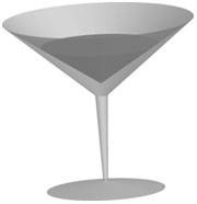
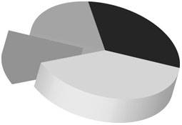
Once you've addressed these two issues, you'll end up with a 3D object that is truly transparent (Figure 7.62, next page). Adding transparency to 3D objects opens new doors to creativity, like creating transparent glass bottles and vases. And don't forget to throw some artwork mapping in there as well. If you map art to a transparent 3D object, you'll be able to see through to the art on the other side. Now you've got to admit, that's pretty freakin' cool, no? Figure 7.62. This martini glass is transparent, allowing you to see what is inside. What If . . . You Blend 3D Objects?In Illustrator, you can select two objects and use the Object > Blend > Make feature to morph one vector shape into another. This technique, as we'll discover in Chapter 9, Graphs, Distortions, and Blends, can be useful for a variety of tasks including shading, special effects, and object distribution. However, what if you created a blend using two 3D objects? Would the 3D effect morph as well, along with the blend? The answer is, yes, it will! If you apply a 3D effect to an object and then duplicate that object (so you have two identical objects), you can create a blend between them. Because 3D is a Live Effect, you can edit the 3D effect of one of the objects and change the position so that you're viewing the object from a completely different angle. The blend will then updateand generate the intermediate steps (Figure 7.63). Figure 7.63. By creating a blend between spheres with mapped artwork, you can create the illusion of the sphere rotating. Not impressed? Well, in Chapter 10, we'll learn how to use blends to create instant Flash animations that you can put on your Web site. That means you can create a box and have it rotate in space. Hey, waitdon't go running off to Chapter 10 yetwe still have plenty of cool stuff to cover in here. What If . . . You Apply a 3D Effect to a Graph?We haven't covered graphs yet (we'll get to that in Chapter 9), but a graph is made up of a group of objects. And because a 3D effect applied at the group level results in all the objects in that group sharing the same effect, what happens if you apply a 3D Extrude effect to a graph? The answer is that you get a powerful way to present numbers in an eye-catching manner (Figure 7.64). And if you add transparency to a 3D graphwell, you can see where that might lead. Figure 7.64. Adding 3D effects to just about anything, like graphs, for example, can turn something ordinary into something unique and attention-grabbing.
|


EAN: 2147483647
Pages: 147