Advanced Path Editing
| Editing paths by hand can be tedious, but it doesn't always have to be. Many times, you'll need to perform certain edits on vector paths, such as removing extra anchor points from a complex path or splitting larger shapes into smaller ones of equal size. Other times, you may need to create outlines of strokes, create duplicate paths at larger or smaller sizes, or simply clean up loose paths and objects in your file. The good news is that Illustrator has a variety of useful path functions that you can use to perform these kinds of tasks. The functions found in this section can all be found in the Object > Path submenu.
Working with the Join and Average CommandsWhen you have two anchor points, you can use the Join command to connect the two points with a straight path. Although this sounds simple, certain requirements must be met in order for the Join command to work:
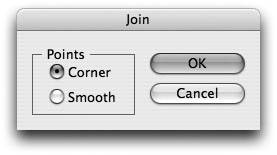
If the two anchor points overlap each other exactly, Illustrator combines the two anchor points and gives you the option of converting the resulting single point to a smooth point or a corner point (Figure 4.32). Figure 4.32. When you are trying to join two overlapping anchor points, Illustrator offers you the option of creating a corner anchor point or a smooth anchor point. The Average function allows you to select at least two anchor points and reposition them by evenly dividing the space between them. You can average anchor points horizontally, vertically, or both horizontally and vertically. There is no limit to how many anchor points you can average at once (Figure 4.33, next page). Figure 4.33. The Average command makes it easy to quickly align multiple anchor points.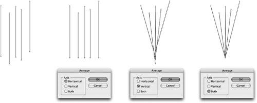
You can also select two anchor points and press Command-Opt-Shift-J (Ctrl-Alt-Shift-J) to perform a combined Average and Join function in one step.
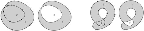
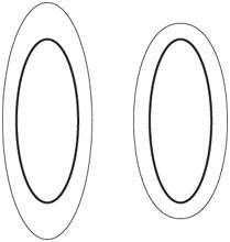
Using the Outline Stroke CommandThe stroke of a path adds thickness to the appearance of the path, but it's an attribute that you can't physically select and manipulate on the artboard. However, you can select a path with a stroke attribute and choose Object > Path > Outline Stroke; when you do, the stroke of that path expands to become a filled shape that you can then edit with the Pen tool. This allows you to tweak the path to make it appear as if the "stroke" is thinner and thicker in different places. There are also times when you might want to convert a stroke to an outline for production reasons. If you have a final version of a logo, converting all strokes to filled paths assures that it will scale properly under all circumstances, because users may forget to turn on the Scale Strokes & Effects setting. Similar to what happens with patterns, when you apply transformations to objects that have strokes or effects applied, the default behavior is that only the shape is transformed, not the strokes or the effects (Figure 4.34). Turning on the Scale Strokes & Effects option in General Preferences changes the default behavior so that strokes and effects are transformed as well. You can also find this setting in the Scale tool dialog. Figure 4.34. If you forget to turn on the Scale Strokes & Effects setting, you can run into problems when scaling artwork. In this example, the text of the logo was reduced, as was the path, but the stroke weight was not scaled. Outlining strokes prevents these kinds of accidents. Exploring the Offset Path FunctionOne of the most useful path functions that exists in Illustrator is Offset Path. When used, this function creates a new vector path that is offset a user-specified amount from the selected object(s). The original selected path is not affected. If you think about it, it's like a scaling functionyou can offset paths to be larger or smaller. But if you've ever tried to scale an object like an oval, you'll know that doing so creates an oval of a different proportion. If you want to create an object that is exactly the same but that has its edges enlarged evenly across the entire object, choose Object > Path > Offset Path (Figure 4.35). Figure 4.35. Scaling an oval shape results in a distorted shape (left). Using the Offset Path function results in a non-distorted result (right).
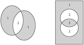
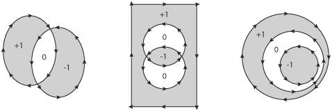
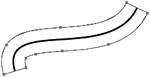
Offset Path works a bit differently depending on the kind of path you have selected. On a closed path, it seems to work as expected, by creating the new path at the offset that you specify. On an open path, however, the Offset Path command creates a new closed path, appearing on both the inside and the outside of the original path (Figure 4.36). Depending on the task, this might mean you need to take an extra step to delete the part of the path that is not needed. Figure 4.36. The Offset Path function, applied to an open path, results in a new closed path. You have to delete a portion of the resulting path if you want an open path.
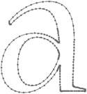
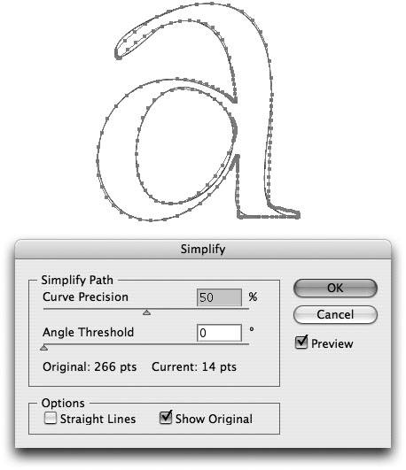
Simplifying Vector PathsEarlier in this chapter, you learned how to use the Remove Anchor Point tool to delete existing anchor points from a path. Although that tool is useful for removing a point or two from a path here or there, it's quite another story when you're trying to remove a lot of anchor points from a path. You may find that some vector paths contain unnecessary anchor points. By unnecessary, we mean that you might be able to create the same path with fewer anchor points. Too many unnecessary anchor points on a path translates into more complex files that take longer to print and that are more difficult to edit (Figure 4.37). Figure 4.37. Paths with numerous unnecessary anchor points are harder to edit and take longer to print. You'll often come across this problem when you're importing files from CAD applications, or when you're using vector tracing programs such as Adobe Streamline (the Live Trace feature in Illustrator CS2, covered in Chapter 8, Mixing It Up: Working with Vectors and Pixels, does not suffer from this problem). To reduce the number of anchor points on a path, select the path and choose Object > Path > Simplify. You can use the Preview option to see the results as you change the settings. The Simplify dialog also gives you real-time feedback on the number of anchor points on the original path and the number of points using the current Simplify settings (Figure 4.38). The dialog also offers the following settings:
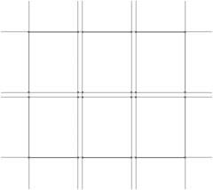
Figure 4.38. When using the Simplify function, you can see real-time feedback on the number of reduced anchor points and the integrity of the shape of the path. Using the Split Into Grid FeatureThe Rectangular Grid tool is great for creating quick grids for illustration purposes, but with it you lack fine control, especially if you want to create guttersspace that appears between columns and rows. Illustrator's Split Into Grid feature takes an existing shape and splits it into a specified number of equal-sized rectangles.
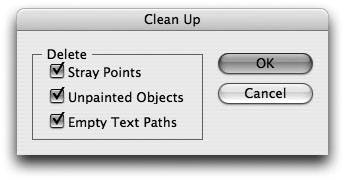
With any vector object selected, choose Object > Path > Split Into Grid to bring up the dialog. Check the Preview button so that you can see the results as you enter the values. Add rows and columns as needed, and also specify a value for the gutter. Illustrator automatically calculates the width and height values for you as you change the other values. At the bottom of the dialog is a check box to Add Guides, which draws guides at the borders of the rows and the columns (Figure 4.39). Figure 4.39. Using the Split Into Grid feature can make it easy to set up layout grids. Removing Unnecessary Elements with the Clean Up FeatureWhile working on revision after revision of a file, your document may become littered with stray anchor points, empty text objects, or unpainted objects (those that have neither a fill nor a stroke attribute applied). Having these objects present in a file can be problematic for a variety of reasons. Empty text objects may contain references to fonts, and you, thinking that those fonts aren't there, may forget to include them when you send source files to prepress. Additionally, stray points in a file can cause files to export with unexpected size boundaries (refer to Chapter 1, The Illustrator Environment, where we spoke about bounding boxes), and could lead to corrupt files. Choose Object > Path > Clean Up and choose which of these elements you want to automatically remove from a file (Figure 4.40). Beware that to Illustrator, a stray point is a single anchor point with no path. Some designers use Scatter brush art by using the paintbrush to click just once to place a single instance of a brush. Running the Clean Up command to delete stray points deletes these scatter brush objects from a file as well. In reality, it's better to use Symbols rather than Scatter brushes for these designer tasks, something we'll discuss in Chapter 5, Brushes, Symbols, and Masks. Figure 4.40. Illustrator's Clean Up feature makes it easy to remove excess elements from a document. |

EAN: 2147483647
Pages: 147