Computer Network Basics
In this chapter, you will learn about
- Home networks and what they are
- Data versus control networks
- Network topologies
- Networking technologies and standards
The foundation of home technology integration (HTI) is a computer network in some form. It’s the emergence of the computer network and the number of options available to create a network in a home that has given rise to the idea that just about any electrical, audio, visual, lighting, or control system can be connected to a network.
Networking a home and a good number of its sight, sound, comfort, and security features provides the homeowner with centralized control and security, not to mention a lot fewer stubbed toes. There are as many reasons to integrate the technology in a home using a network as there are homes and homeowners. However, in the end, all of these reasons are based around a single concept—the home network.
Computer Networks in the Home
A home computer network can be as simple as two PCs connected by a communications medium that share files, perhaps a printer, or maybe even an Internet connection. However, a home computer network can also be something very complex and sophisticated such as an integrated music, video, lighting, and security system that at the touch of a button arms the security system in home mode, turns the audio video (AV) equipment on, closes the drapes, drops the video screen, and starts the movie playing. There are no actual configuration limits to what a home computer network can be designed to do. Computer networks, including home computer ones, exist for the sole purpose of sharing resources, such as peripheral devices (like a printer, scanner, or audio source), data files, and other computer-connected resources.
Computer Networks
A computer network is created whenever two or more computers are directly connected using a communication medium, such as a parallel port, serial port, network cable, or a wireless connection, and some level of resource sharing is initiated by or for the computer’s users.
Figure 10-1 illustrates a very basic computer network, representative of what might be found in a home computer network. The two computers shown have the capability to share data files, provided each user has granted permission to the other user, and they share a printer.
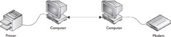
Figure 10-1: A computer network in its most basic form allows two computers to share information and devices.
The computers that make up a home network can be connected to each other in a variety of ways, including dedicated network cabling or wiring, a wireless radio frequency (RF) signal, or perhaps the alternating current (AC) electrical wiring, cable TV wiring, or telephone wiring in the home.
More often than not, a home network is installed for the purpose of sharing a single Internet connection. Regardless of the type of Internet service in use, having separate lines for every computer in a home is not only very expensive, but also with today’s technology, completely unnecessary. The PCs on a home network can share not only a connection to the Internet, but also virtually every peripheral and data file on any computer on the network. In some instances, users on the network can even share software, such as multiplayer games.
Most high-speed broadband services (cable, digital subscriber line (DSL), Integrated Services Digital Network (ISDN), and fixed terrestrial wireless) provide an in-home device (modem, bridge, or router) that can be used to share the communications line (and the access to the Internet) directly. The latest versions of Windows and the Apple MAC Operating System (OS) include software support for sharing a single dialup connection as well as connections across a local network.
A home computer network can be used to share or distribute digital audio or video files between devices in a home. For example, digital music can be transmitted over the network to other PCs or stereo receivers in the home and played through their speakers. Separate rooms can receive a different digital music stream, depending on who’s in the room and his or her taste. The same is true for digital video streams.
Control Networks
The type of network described in the preceding section is also called a data network, because the signals transmitted between the computers (also referred to as nodes) on the network represent various forms of data, including text, graphics, and sound signals encoded in digital/data form.
Another type of network is a control network, which is used to manage and control lighting, Heating, Ventilating, Air Conditioning (HVAC), appliances, and home security systems. Control networks use computer-based controllers and receivers. Control networks are also called home automation networks and home technology integration networks. A common control network found in most modern homes is that made up by the heating and cooling system and a thermostat.
The essential components in a control network are the controller and receivers. The controller and receivers can either be hardware devices or software running on a computer. The controller transmits commands and control data across the network to the receiver, which either acts on the incoming data or retransmits to another device, such as an appliance, stereo, light fixture, or whatever has been attached to the network for automation purposes. For example, if you wish to have your home’s outside lighting and a random set of inside lights turned on and off while you are away on vacation, you program the controller with the pattern you wish to use and as the scheduled events are triggered, the controller transmits the appropriate on or off signal to the receivers managing the applicable lighting fixtures.
As illustrated in Figure 10-2, a control network in a home can manage the heating and cooling, security cameras inside or outside of the home, the lighting inside and outside the home, and even the lawn sprinklers or the coffee pot using localized or built-in receivers.
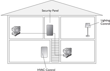
Figure 10-2: A control network is used to control, monitor, and manage one or more of a home’s systems.
Network Topologies
The physical layout of a network is its topology. A network can be set in a single serpentine line that winds through the rooms of a home; it can be set in a loop that runs throughout the home starting and stopping in the same place; or each of the networked devices can have its own direct line to a central point. These three options are the basic topologies used to define the layout of a network. Respectively, they are called bus, ring, and star, also called “home run.”
Bus Topology
A bus topology gets its name from the term electrical bus, which is a circuit wire that carries an electrical signal. The central element of a bus topology network is a single cable that runs the length of the network—the network trunk line or “backbone” cable. Devices attaching to the network are connected directly to the cable or through clustering devices, such as a hub. Figure 10-3 illustrates a bus topology network connected in what is called a “daisy-chain.” The arrangement shown in Figure 10-1 is common when coaxial cable is used as the network backbone.
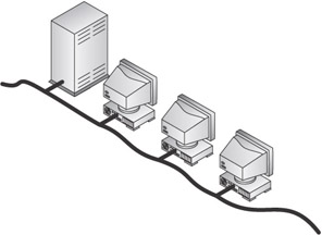
Figure 10-3: An example of a network using a bus topology
Another example of a bus topology network is shown in Figure 10-4. In this illustration, the networked devices connect to the backbone using short cables, called patch cables or cords. Understand that this illustration is highly simplified. Later in this chapter, we look at exactly how the connection is made, but for now, understand that the networked devices connect to the network backbone.
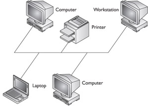
Figure 10-4: Another view of a bus topology network
Ring Topology
The second of the top three network topologies is the ring topology, which gets its name from the fact that this topology is installed in a loop (or ring) that circles back around to connect the end of the network with the beginning of the network. To understand the concept behind a ring topology, take a pencil and begin drawing a circle on a piece of paper. If the line you drew were the network cable, the fact that the end of the cable connects back to the beginning of the cable is what makes it a ring topology.
Figure 10-5 illustrates how a ring topology might actually look when installed in a home or an office building. Only starting and ending the network backbone cable at the same place creates the “ring.” Placed into a home networking situation, a ring network might look something like the network shown in Figure 10-6.
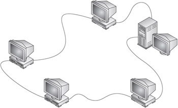
Figure 10-5: An example of a ring topology network
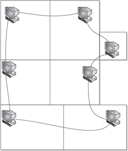
Figure 10-6: A ring topology used with a home network might not actually look much like a “ring.”
Star Topology
The third of the three most common network topologies is the star topology. In much the way that the name “ring” describes the general layout and topological shape of a ring topology network, the name “star” does the same for a star topology network.
The star topology defines a network structure that emanates from a central unit, such as a server, switch, hub, or another type of networking device. The star topology may resemble a starfish more than it does a heavenly body, but the fact that its network devices each have a direct line connection to the central unit like the points of a star, or the arms of a starfish, is where this topology gets its name. The star topology is sometimes also called hub-and-spoke because of its central device and the home run to each connected device.
In virtually all home situations a star topology is usually the least expensive, the easiest to install, provides the most flexibility, and offers the most fault tolerance, or built-in resistance to failure, than the other topologies.
Figure 10-7 illustrates a very basic star topology network that uses a network hub as its central device. Actually, the configuration shown is very common to Ethernet networks, which we talk about in the next section, “Hybrid Star Topologies.”
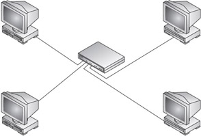
Figure 10-7: A network segment using a star topology
| CROSS-REFERENCE |
See Chapter 11 for more information on hubs and other networking hardware. |
Hybrid Star Topologies
A hub is a networking device that clusters several devices together and connects them either directly or indirectly to the network backbone or trunk line. Chapter 11 explains the function of a hub in more detail, but for now just see it as a way to connect multiple devices that are located in close proximity to the network trunk.
If the starred cluster shown in Figure 10-7 were connected to the backbone cable along with a few other stars created in the same way, the resulting topology would look something like the one shown in Figure 10-8. Figure 10-8 is a hybrid topology that combines the bus and the star topologies.
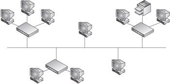
Figure 10-8: An example of the hybrid star-bus network topology
Figure 10-9 illustrates another hybrid star topology. Only this time, the star topology is combined with the ring topology to create a ringed-star or a star-ring hybrid.
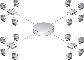
Figure 10-9: An example of the hybrid star-ring network topology
In their purest form, bus, ring, and star topologies can be implemented fairly easily. However, in practice, it is much more common for a topology to be installed in one form of hybrid topology or another.
Another hybrid network topology is the mesh topology. This topology, which provides the ultimate in fault tolerance, requires that every network device be connected directly to every other network device, creating a mesh of wiring. With this topology in place, the network isn’t dependent on any one path through the network.
When we discuss Ethernet and Token Ring networking in the next section, “Networking Technologies,” you should get a better understanding of why a hybrid is commonly used.
Networking Technologies
While network topologies provide a general guideline for the layout of a network, the primary two networking technologies, Ethernet and Token Ring, provide the specifications and rules that define the functionality of the network itself.
Of these two, Ethernet is by far the most commonly implemented and most likely the one you’d choose to install in a home networking environment. Token Ring networking technology is harder to find, more expensive, and more complicated to configure. On the other hand, it is very dependable. Ethernet networking components are readily available, inexpensive, and relatively simple to install and configure, which are most of the reasons it is also the more popular choice.
Ethernet
Ethernet is not actually a thing; it is a standard specification for a networking technology that defines the types of wiring that should be used, the type and speed of the signals transmitted over the wiring, and how to control and restrict access to the network to prevent an electrical signal logjam on the wire.
The Ethernet standard was developed by the Institute of Electrical and Electronics Engineers (IEEE, pronounced as “eye-triple-eee”), a trade organization that took it upon itself to standardize the specification and characteristics of low-voltage networks, including data networks. In February of 1980, the IEEE gathered groups of interested parties, divided them into narrowly focused subcommittees charged with defining network standards compatible with the networking model standard published by the International Organization for Standardization (ISO), the Open Systems Interconnect Reference Model, or the OSI reference model, as it is more commonly called.
The IEEE 802 (802 is for 1980, February) committees were numbered to differentiate their responsibilities, and the standard each committee produced took on the number of the committee writing it. Table 10-1 lists the committees of the IEEE 802 project and the networking specification each is charged with defining.
|
IEEE 802.3 Subcommittee |
Responsibility |
|---|---|
|
802.1 |
Internetworking |
|
802.1d |
Spanning Tree Protocol |
|
802.1s |
Multiple Spanning Trees |
|
802.1q |
VLAN Frame Tagging |
|
802.2 |
Logical Link Control |
|
802.3 |
Ethernet (CSMA/CD) |
|
802.3u |
Fast Ethernet |
|
802.3z |
Gigabit Ethernet |
|
802.3ae |
10 Gigabit Ethernet |
|
802.4 |
Token Bus |
|
802.5 |
Token Ring |
|
802.6 |
Distributed Queue Dual Bus (MAN) |
|
802.7 |
Broadband Technology |
|
802.8 |
Fiber Optic Technology |
|
802.9 |
Voice/Data Integration |
|
802.10 |
LAN Security |
|
802.11 |
Wireless Networking |
|
802.11a |
54 Meg Wireless Network |
|
802.11b |
11 Meg wireless Network |
|
802.12 |
Demand Priority Access LAN (100BaseVG-AnyLan) |
|
802.15 |
Wireless Personal Area Network |
|
802.16 |
Wireless Metropolitan Area Networks |
|
802.17 |
Resilient Packet Ring |
|
802.18 |
LAN/MAN Standards Committee |
|
802.19 |
Technical Coexistence |
|
802.20 |
Mobile Broadband Wireless Access (MBWA). |
Token Ring
Originally Token Ring, the common implementation of ring topology networks, was an IBM thing. However, in today’s world there are a number of vendors providing Token Ring equipment. Apple Computer supports a version of ring networking it calls TokenTalk, in contrast to its Ethernet product, AppleTalk.
In a home networking setting, installing a ring network is not typical, but doing so is completely possible provided you have the budget for the hardware, which tends to be more expensive than Ethernet equipment.
The OSI Model
The OSI model is something you need to know because it is used as the common frame of reference in networking. Typically, networking devices and software are discussed in regard to the OSI layer on which they are defined.
Reasons for a Layered Model
A networking model defines the formats, functions, and services performed to transmit data from a sending device across a network to a destination device. However, a layered networking model defines these activities in discrete, yet interoperable, layers. The benefits of working with a layered model are that developments or changes to one layer’s specification should have very little or no impact on the other layers and it provides a structured approach to troubleshooting. In a networking model, a router manufacturer can modify the functionality of its equipment operating at Layer 3 (see “The Layers of the OSI Model”) and the manufacturers of equipment operating at Layers 2 or 4 would remain compatible and able to communicate with the Layer 3 devices.
The Layers of the OSI Model
The OSI reference model is separated into seven layers. Each one specifies a distinct group of functions that must be performed to transmit data from one network node to another. Figure 10-10 shows the layers of the OSI reference model from Layer 1 (Physical layer) to Layer 7 (Application layer).
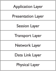
Figure 10-10: The Layers of the Open Systems Interconnect (OSI) reference model
| Tip |
Bear in mind that the OSI reference model isn’t software or even firmware, (programming statements embedded in an electronic circuits). The OSI reference model is a written specification that defines what must happen on each of its seven layers to get data from point A to point B. |
Here is a brief description of what each of the OSI model’s layers defines.
- Layer 7–Application layerThis layer provides services to the software through which the user requests network services. The Application layer doesn’t contain any applications, which means that PC application software isn’t on this layer. In other words, programs like Microsoft Word or Corel’s WordPerfect are not included in the specifications of this layer. However, software that interfaces with the activities of the network, such as browsers, FTP clients, and mail clients are.
- Layer 6–PresentationThis layer is concerned with data representation and code formatting, including ASCII, EBCDIC, compression, and encryption.
- Layer 5–SessionThis layer establishes, maintains, and manages the communication session between computers.
- Layer 4–TransportThe functions defined on this layer provide for the reliable transmission of data segments as well as the disassembly and assembly of the data before and after transmission.
- Layer 3–NetworkThis is the layer on which routing is specified. The Network layer defines the processes used to route data across the network and the structure and use of logical addressing, meaning Internet Protocol (IP) addressing.
- Layer 2–Data LinkAs its name suggests, this layer is concerned with the linkages and mechanisms used to move data about the network, including the specification about accessing the network.
- Layer 1–PhysicalThis layer defines the electrical and physical specifications for the networking media that carry the data bits across a network.
Review
Home networks are installed for a variety of reasons, including sharing devices, files, and a connection to the Internet. However, a control or home automation network includes the controllers and receivers that control the electrical and electronic devices in the home, including stereos, televisions, lighting, heating and cooling systems, and security.
The most common network topologies are bus, star, and ring. The bus topology is the most commonly installed network topology in business networks, but the star topology, installed as a hybrid star-bus topology, is far more common in home computer networks. The star topology is the easiest to install and provides the most fault tolerance—resistance to hardware or software failure.
The network technology most associated with the bus and star topologies is Ethernet, which is by far the most common network technology in use. Token Ring networks, which are installed on the ring topology, are more expensive to install.
The OSI reference model is a networking model that breaks the activities involved in transmitted data across a network into seven discrete layers. It is not emphasized on the HTI+ exam, but you should be familiar with the layers for reference purposes.
Questions
- What type of network manages and monitors household appliances, heating and cooling systems, and audio and video systems?
- Computer network
- Integrated network
- Control network
- Hybrid network
- Which of the following best describes the composition of a basic computer network?
- Multiple stand-alone computers in a single room
- Two computers connected by a communications wire for the purpose of sharing resources
- Two computers that can share the same removable media
- Multiple computers in a single room that each has a separate Internet connection
- Which of the following is not a common network topology?
- Bus
- Ring
- Redundant
- Star
- Which network topology is the easiest, least expensive, and most fault tolerant to install?
- Bus
- Ring
- Mesh
- Star
- What are the essential components of a control network?
- Transmitters and receivers
- Transceivers
- Controllers and receivers
- Emitters and receivers
- What is the term that describes the physical layout of a network?
- Schema
- Grid
- Plant
- Topology
- Which of the common network topologies is based on a central “backbone” that runs the length of the network?
- Bus
- Ring
- Mesh
- Star
- Which of the common network topologies involves the use of a central clustering device?
- Bus
- Ring
- Mesh
- Star
- What is the standard specification for Ethernet networks?
- IEEE 802.2
- IEEE 802.3
- IEEE 1284
- IEEE 1394
- What is the common name used for Layer 1 of the OSI model?
- Physical layer
- Network layer
- Transport layer
- Application layer
Answers
- C. The world of home technology integration is also the world of home automation networks on which the electronic systems in the home can be integrated for control and management purposes. A home computer network typically doesn’t include control of heating, lighting, etc. The other answers may be good descriptive terms, but they aren’t used to name network types.
- B. As few as two computers can make up a network, provided they are connected for communications and set up to share resources. None of the other choices would be a network.
- C. I made this one up, actually. All of the other answers are valid topologies.
- D. A star network is generally the least expensive to install because a line runs directly from each device to a central device. If one device fails, the others are unaffected. Bus, ring, and mesh topologies typically require additional hardware and software, and, in the case of mesh topology, a whole lot of additional cable.
- C. Controllers and receivers are the terminal devices of a control network. Perhaps a case can be made for transmitters and receivers, but the purpose behind a control network is control.
- D. The term topology is used to describe the physical layout of a network’s media and nodes. A schema is a database plan and grid and plant are physical facility layout terms.
- A. A bus network includes a backbone that runs the length of the network. A ring network also uses a central connecting cable, but it is referred to as the ring. Mesh and star topologies use direct connections to each node.
- D. Regardless of whether it is used as a hybrid or a common star network, a central device is used to cluster the nodes to the network servers or backbone.
- B. IEEE 802.2 defines the Data Link layer’s sublayer functions, including MAC addressing. IEEE 1284 is a parallel cable standard. IEEE 1394 defines high-speed serial interfaces. This leaves IEEE 802.3 as defining Ethernet standards.
- A. Layer 1 of the OSI model is the Physical layer. Layer 3 is the Network layer; Layer 4 is the Transport layer; and Layer 7 is the Application layer.
Part I - Home Technology Installation Basics
- Wire and Cable Basics
- Connector Types and Uses
- Wiring Installation Practices
- Codes, Standards, and Safety Practices
Part II - Structured Wiring
- Infrastructure Wiring Basics
- Planning a Structured Wiring Installation
- Rough-In Installation
- Trim-Out Installation
- Troubleshooting Structured Wiring
Part III - Home Computer Networks
- Computer Network Basics
- Computer Network Hardware
- Computer Network Software
- Designing and Installing a Computer Network
- Troubleshooting a Home Network
Part IV - Audio/Video Systems
- Distributed Audio System Basics
- Designing and Installing Distributed Audio Systems
- Distributed Video Basics
- Designing and Installing Distributed Video Systems
- Troubleshooting Audio Systems
- Troubleshooting Video Systems
Part V. Home Lighting Management Systems
- Home Lighting Basics
- Home Lighting Devices
- Designing a Home Lighting Control System
- Installing a Home Lighting Control System
- Troubleshooting and Maintaining Lighting Control Systems
Part VI - Telecommunications
- Home Communication System Basics
- Designing and Installing a Home Telephone System
- Troubleshooting a Home Communication System
Part VII - HVAC and Water Management
Part VIII - Security System Basics
- Security System Basics
- Designing a Home Security System
- Installing a Home Security System
- Troubleshooting and Maintaining a Home Security System
- Home Security Surveillance Systems
- Home Access Control Systems
Part IX - Home Technology Integration
- Defining Users Needs and Desires
- User Interfaces
- Home Automation Controllers
- Programming
- Integrating the Connected Home
- Other Home Technology Integration Devices
Part X - Appendices
EAN: N/A
Pages: 300
