Troubleshooting a Home Communication System
Troubleshooting a HomeCommunication System
In this chapter, you will learn about
- Common voice communication system problems
- Troubleshooting telephone system problems
- Communication system troubleshooting tools
- Testing communications cabling
Of all of the various systems in a home, the one that people can’t seem to live without is the telephone system. So when problems develop, even minor problems can seem like an emergency. Your ability to diagnose, troubleshoot, isolate, and resolve a problem on a home’s communication system becomes extremely important to restoring the home’s ability to communicate with the outside world.
This chapter is focused on identifying the problems common to home communication systems and the methods and tools used to resolve these problems quickly and efficiently. The good news is that in a structured wiring environment, many of the processes used are the same used to troubleshoot wiring and connection problems for most of the other systems in a home. As a home technology integration professional, you must know which troubleshooting process is used to identify and isolate each type of problem.
Wiring Issues
The telephone company’s responsibility for problems on a home communication system ends at the demarcation point or network interface device (NID), which is where the telephone company’s lines terminate at the home. Beyond the NID, the wiring that provides telephone service throughout a home is considered to be customer premise inside wiring (CPIW) by the phone company. The homeowner is responsible for any problems that occur with the CPIW, unless the homeowner purchases wire maintenance services from the telephone company and even then there are limits to what the telephone company will service.
NID Wiring
Basic telephone wiring is a four-wire cable that actually consists of two pairs of wire. As shown in Figure 28-1, the wires in the incoming telephone wiring connected into the NID are green, red, black, and yellow. The green and red wires are treated as one pair and the black and yellow wires are treated as another pair. Each pair of wires carries the tip and ring signals used by a telephone to connect and communicate. As shown (Figure 28-1), the green wire is the tip wire in pair one and the black wire is the tip wire in pair two. The red and yellow wires provide the ring link in each pair, respectively.
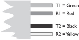
Figure 28-1: The wires in a four-strand telephone wire (quad wire)
The NID is usually located on an outside wall of the house. At the NID (see Figure 28-2), each incoming line uses one of the two pairs in the telephone cable and if only a single line is entering the home, by telephone company standards, the red and green wires are connected to the point where the CPIW attaches to the NID. If a second line is provided, then the yellow and black wires are also connected. However, when connecting a second line, the black wire is treated as if it were green and the yellow wire as if it were red. If more than two lines are entering the home, the incoming wiring is likely to be Cat 3 cable with its four wire pairs. See Table 28-1 for color-coding of wiring.
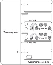
Figure 28-2: In the NID, each incoming telephone line is connected separately.
|
Cat 5 Wire Color |
Quad Wire Color |
Function |
|---|---|---|
|
White-Blue |
Green |
Line 1 Tip |
|
Blue |
Red |
Line 1 Ring |
|
White-Orange |
Black |
Line 2 Tip |
|
Orange |
Yellow |
Line 2 Ring |
|
White-Green |
N/A |
Line 3 Tip |
|
Green |
N/A |
Line 3 Ring |
|
White-Brown |
N/A |
Line 4 Tip |
|
Brown |
N/A |
Line 4 Ring |
One wiring problem you might run into inside the NID is that in situations where the red or the green wires have become damaged, the black and yellow wires may have been used to replace them instead of installing a new run of quad wire back to the distribution point. If you encounter this, and a second line is being installed, the phone company will need to replace their service line with a good four-wire cable.
Cat 5 and the NID
When Cat 5 wiring is connected to an NID, there are no red, green, yellow, and black wires to use, only blue, orange, green, and brown. If one or more lines in a home are having connection problems, the problem may be wiring inconsistencies at the NID.
Each of the four wire pairs in a Cat 5 cable can be used to replace the green and red (tip and ring) wires required for the connection. Table 28-1 lists the wire color replacement convention when using Cat 5 in place of quad wire. As you can see, the white striped wire in each pair replaces the “green” wire (tip) in the telephone convention and the solid color wire in the pair replaces the “red” wire (ring).
| Note |
A good way to remember the order that the Cat 5 colors should be used for multiple telephone lines is to remember that the colors go from sky to earth: blue sky, then orange sunset, green trees, and brown dirt. |
The order and assignment of the Cat 5 wire pairs listed in Table 28-1 should be used throughout the home communications system. It is very important to use the same wiring scheme throughout a system to ensure conformity and consistency, since this can eliminate at least one potential problem when you have to troubleshoot the system.
Troubleshooting the NID
If a telephone line is dead on all inside telephones as well as at the structured wiring distribution panel, the problem could very well be with the incoming telephone line. To troubleshoot the connections in the NID, follow these steps:
- Locate the test jack (Figure 28-3) for the incoming line in question inside the NID.
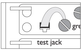
Figure 28-3: Each incoming telephone line connection in the NID has a test jack. - Ensure the RJ-11 plug connected to the green wire’s setscrew is inserted into the jack securely.
- You should remove and reinsert the plug into the test jack and recheck the problem telephone line to see if the problem wasn’t just a problem with the connection at the test jack.
- If the problem persists, remove the plug and connect a good telephone handset directly into the test jack. Removing the plug disconnects that line from the CPIW. When you insert a plug connected to the handset, the line is now connected directly to the telephone company’s distribution system. If the line is still dead (no dial tone) then the problem is on the telephone company’s lines and they should be notified of the problem.
- However, if plugging directly into the test jack yields a dial tone, try calling a working telephone number to make sure there are no other problems on the telephone line.
- If the line is working normally, then the problem is with the CPIW and you need to troubleshoot the structured wiring connected to the communications system (more on this later in the chapter).
Inside Wiring Issues
If a telephone line is working at the NID, but not inside the home, the problem is most likely a wiring problem somewhere between the NID and the structured wiring panel or the telephone outlets (assuming you’ve already checked the handset and the telephone patch cord connecting it to the outlet).
The best way to troubleshoot exactly where the problem may be is to connect a handset to each connection point along the cable path. When you find the point where there is no dial tone on the phone, you can then begin to determine why that link is not working. Some common problems on the faulty link to look for are
- Loose setscrewCheck any terminal strips or setscrew connections to ensure they are tightened down. You should check the NID for this condition as well.
- Reversed wiresThe wires in a wire pair may be reversed or two pairs may be reversed or a split pair condition may exist.
- Faulty terminationVerify that the plug and jacks are securely attached to the cable. Check the wire pinout used in an RJ-11 or RJ-45 jack and plug. Replace the termination with the correct pinout, if needed.
- Wire damageIf some telephone jacks have phone service but others don’t, the problem may be a damaged cable where only one or two wire pairs are shorting to each other because the cable has been cut or pierced. To verify this condition, you should run length, TDR, and wire map tests (discussed later in the chapter).
Interference and Noise
If a homeowner is complaining about hum, static, or that conversations on one of a home’s telephone lines can be heard on another, the issue is likely in the wiring somewhere.
Here are some common wire issues that can create noise on a telephone line:
- If the outer jacket of a cable is cut and even a small hole is opened, static or crackling may be heard on the phone lines attached to that cable. If even a small amount of moisture enters the cable, it can create a low-level short between two or more pairs, which may be heard on the line as static, snapping, or crackling.
- If there are any loose or poorly done splices (heaven forbid!), taps, or loose connections between the distribution panel and an outlet, users may hear static, buzzing, or a hum on the line. If there are any splices or taps in the line, they should be removed and any loose connections repaired or replaced.
- If the users complain of a loud hum on a line, the problem is likely a connection made to a grounded line. The connection should be redone avoiding the ground. You will need to retrace the wiring back to the main electrical panel to identify the circuits connected to the main’s ground then reconnect the telephone wiring to avoid a connection to these circuits.
- If the outlet has a line splitter installed and a fax machine, answering machine, or even another telephone is sharing the line, it can add noise to the line when they are in use. If the other equipment has permanent needs, additional lines should be installed to service them.
- The telephone patch cords that come with telephone sets are also called line cords, but they aren’t always the best quality. A faulty or poor quality line cord can create noise on the line at the handset.
- EMI and RFI can be a problem for communication systems that are installed on UTP. If all other troubleshooting tests fail to identify the source of noise on a line, verify the placement of the UTP cable and ensure that it is installed per the EIA/TIA guidelines regarding other electrical equipment and AC power lines.
Connector Issues
When a second phone line is added to an existing telephone system, the outlet jacks and wiring blocks are commonly overlooked. If the original installation didn’t provide wiring blocks and jacks that were pre-wired for two or more lines, the wiring connecting the second line to the outlet is virtually dead-ended. Whenever installing new wiring, be sure to terminate all wires and connections.
If a phone line isn’t working for only a single outlet or handset, check the termination of the home-run cable at the wiring block or structured wiring panel and into the jack. An RJ-11 plug will connect into an RJ-45 jack. So, verify that the RJ-45 jack has been terminated for a telephone connection and not a data network connection. Use Table 28-1 from earlier in the chapter and the information in Chapter 13 to differentiate these connections.
HomePNA Issues
If a Home Phoneline Networking Alliance (HomePNA) networking system is installed on telephone circuits that are still in use for voice communications, problems with line noise on the circuit can greatly affect the performance of both the data network and the telephone system.
In addition to correcting the interference and noise issues listed earlier in the chapter, you may also need to install a low-pass filter between the computers and their HomePNA connections.
Cable Testing
The cable conditions that can impact the performance of a home communications system are the same as those that can affect all other systems connected to the structured wiring system.
Common Wire Faults
The more common cable faults that can affect the telephone system are
- Crossed pairThis condition occurs when a wire pair is connected to different pins on each end of a cable run. For example, if wire pair 2 is connected to pins 4 and 5 on one end of the cable and pins 7 and 8 on the other end.
- Improper impedanceAlthough a connector terminating a Cat 5 cable appears to be attached correctly, the connector may not measure at 100 ohms, which is the normal impedance for Cat 5 cable. If the connector and the cable have different impedance, signal reflections can occur. Another problem that can affect the impedance of a cable is a very sharp bend or kink in the cable causing the cable to not test out at 100 ohms.
- Open circuitThis condition is caused when a cable pair doesn’t have continuity between the ends of a cable. This is the most common problem with copper cabling.
- Reversed pairThis condition occurs when the tip and ring wires of a telephone line are reversed at the termination of one end of the cable. For example, if one of the wires in pair 2 is connected to pin 1 on one end of the cable and pin 2 on the other end, and the other wire in the wire pair is connected between pins 2 on one end and pin 1 on the other end, the telephone signals will be transmitted or received improperly.
- Short circuitIf two of more conductors in a cable are in contact (metal to metal), it creates a short circuit, which is like a roadblock for signals traveling on the cable pairs affected.
Working Safe
A telephone circuit carries electrical currents in various voltages that are also present in any connectors and terminal screws. If the phone line you are working on is connected through to the NID and a call comes in on that line, you could get an electrical shock.
Here are some tips for working safely on a telephone circuit:
- Ensure that the cable you are working on is not connected directly or indirectly to the NID. If you cannot disconnect the cable from the NID, set the handset portion of the telephone so it is not in its cradle, which busies out the phone.
- Use screwdrivers that have insulated handles
- Don't touch bare conductor wires or screw terminals with your hands or body
- I hope this one is obvious, but don't work on a telephone circuit during a lightning storm.
Wire Testing Tools
When testing UTP cabling used for a communications system, the tools used are essentially the same used for testing UTP in a data network (see Chapter 14). The following list provides an overview of the testing tools most often used to troubleshoot the cables in a communications system:
- Cable certification testersThis tool can be used to verify that a cable meets the performance standards specified in TIA/EIA TSB-67, the test standard for network cable. The tests performed by a certification tester are impedance, length, attenuation, wire map, and near-end crosstalk (NEXT).
- MultimeterWhether analog or digital, a multimeter measures voltage, current (amps), and resistance (ohms) on copper wiring. If used with a shorting device, a multimeter can also test for continuity. Performing an ohms test with a multimeter is one way to identify an open circuit on a cable.
- Telephone test setThis tool is used to simulate the functions of a telephone system and to perform circuit diagnostics and perform standard telephone cable testing.
- Time Domain Reflectometry (TDR) testersA TDR test is performed to identify any problems or defects on a cable and its termination, but TDR tests are most commonly used to measure cable length or pinpoint the location of a problem on a cable.
- Wire map testerThis tool, also called a pair scanner, is used to test for opens, shorts, crossed pairs, split pairs, and reversed pairs on a UTP cable.
CROSS-REFERENCE Chapters 9 and 14 cover structured wiring and data network cable testing in more detail.
Review
The telephone company’s responsibility for problems on a home communication system ends at the demarcation point or network interface device (NID) of a home. Beyond the NID, the telephone wiring is customer premise inside wiring (CPIW), and is the responsibility of the homeowner.
Basic telephone wiring is a four-wire cable (also called quad wire) that has green, red, black, and yellow wire. The green and red wires are treated as one pair and the black and yellow wires are treated as another pair. Each pair of wires carries the tip and ring signals used by a telephone to connect and communicate. The four wire pairs of a Cat 5 cable can be used for the tip and ring wires of the telephone connection.
If a telephone line is dead on all inside telephones as well as at the structured wiring distribution panel, the problem could very well be with the incoming telephone line. If a telephone line is working at the NID, but not inside the home, the problem is most likely a wiring problem somewhere between the NID and the structured wiring panel and the telephone outlets. Some common problems on the faulty link you may want to look for include: loose setscrew, reversed wires, faulty termination, and wire damage. Many common wire faults can create noise on a telephone line.
The common cable faults that can affect the telephone system include: crossed pair, improper impedance, open circuit, reversed pair, and short circuit.
The testing tools that should be used to troubleshoot the cabling of a communications system include: cable certification tester, multimeter, telephone test set, TDR tester, and wire map tester.
Questions
- At what point do the telephone company’s responsibilities end for the telephone wiring of a home?
- Distribution panel
- Network interface device
- Telephone handset
- Telephone outlet
- What are the two functions associated with the wires of a telephone circuit?
- Dial tone
- Ring
- Caller ID
- Tip
- If Cat 5 wiring is used to distribute telephone service throughout a home, what is the basic color of the wire pair used to replace the wires used for Line 1?
- Blue
- Orange
- Green
- Brown
- After determining that a telephone line is dead on all circuits inside a home, what should be checked to determine if there is a problem with the incoming telephone line?
- Distribution panel
- NID
- Inside cable
- None of the above; only the telephone company can make this determination.
- Which of the following would be the prime suspect when no interior handsets are able to get a dial tone?
- Damaged wiring
- Faulty termination
- Loose test jack or connection in the NID
- Reversed wires
- Which of the following can be a cause of static or other noise on a telephone line?
- Cat 5 cabling
- Spliced cabling
- RJ-45 connectors
- Low-pass filters
- What is the condition created when the conductors of a wire pair are connected to different pins of a terminator at each end of a cable?
- Crossed pair
- Open circuit
- Reversed pair
- Short circuit
- Cat 5 cabling should have 100 ohms of impedance. When used in a communications system, how much impedance should the terminations of a Cat 5 cable have?
- 50 ohms
- 75 ohms
- 100 ohms
- 150 ohms
- What testing device is most commonly used to measure voltage, current, and resistance?
- Cable certification tester
- Multimeter
- TDR
- Wire map
- Which testing device is commonly used to test for opens, shorts, crossed pairs, split pairs, and reversed pairs on a UTP cable?
- Cable certification tester
- Multimeter
- TDR
- Wire map
Answers
- B. This device is also called the demarcation point, or demarc for short. The other devices listed are all interior devices, which are the responsibility of the homeowner.
- B and D. These functions are used to complete the circuit on a telephone line.
- A. The order of the wires used for Lines 1 through 4 of a telephone system is blue, orange, green, and brown.
- B. The incoming line can be checked using the test jack inside the NID.
- C. If the plug in the test jack isn’t properly seated or wires aren’t secure on the connection terminals, the line may be interrupted before it can enter the home.
- B. In a structured wiring system, there are no spliced wires, but if in an existing system, the wire is spliced or tapped, a bad connection can cause noise on the line.
- A. The signals on the telephone line would not be properly received or transmitted.
- C. The impedance must match on the cable and its terminations.
- B. The other devices listed are used for higher-level and more complicated testing procedures.
- D. A wire map tester is used to test wire pairs on category UTP cable.
Part I - Home Technology Installation Basics
- Wire and Cable Basics
- Connector Types and Uses
- Wiring Installation Practices
- Codes, Standards, and Safety Practices
Part II - Structured Wiring
- Infrastructure Wiring Basics
- Planning a Structured Wiring Installation
- Rough-In Installation
- Trim-Out Installation
- Troubleshooting Structured Wiring
Part III - Home Computer Networks
- Computer Network Basics
- Computer Network Hardware
- Computer Network Software
- Designing and Installing a Computer Network
- Troubleshooting a Home Network
Part IV - Audio/Video Systems
- Distributed Audio System Basics
- Designing and Installing Distributed Audio Systems
- Distributed Video Basics
- Designing and Installing Distributed Video Systems
- Troubleshooting Audio Systems
- Troubleshooting Video Systems
Part V. Home Lighting Management Systems
- Home Lighting Basics
- Home Lighting Devices
- Designing a Home Lighting Control System
- Installing a Home Lighting Control System
- Troubleshooting and Maintaining Lighting Control Systems
Part VI - Telecommunications
- Home Communication System Basics
- Designing and Installing a Home Telephone System
- Troubleshooting a Home Communication System
Part VII - HVAC and Water Management
Part VIII - Security System Basics
- Security System Basics
- Designing a Home Security System
- Installing a Home Security System
- Troubleshooting and Maintaining a Home Security System
- Home Security Surveillance Systems
- Home Access Control Systems
Part IX - Home Technology Integration
- Defining Users Needs and Desires
- User Interfaces
- Home Automation Controllers
- Programming
- Integrating the Connected Home
- Other Home Technology Integration Devices
Part X - Appendices
EAN: N/A
Pages: 300
