Completing the Multicasting System
This section provides an overview of the processes used to send and receive a multicast stream. The source, a Windows Media server, generates and sends the multicast IP packets. The client, Windows Media Player, receives and renders the packets. All of the routing of the packets is handled by messages and timers. The messages provide or request information, and the timers wait for responses.
Note that the term “aware” is a shorthand description of what happens when a router processes and stores information received from other routers. For example, when router A receives a hello message from router B, we say that router A is now aware of B.
Figure 22.3 shows a portion of a shared tree containing clients, a server generating a stream, the routers and switches that create the path for the stream, and the RP through which hundreds or thousands of clients can receive the stream.
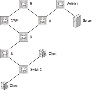
Figure 22.3: A multicasting shared tree.
Configuration and Operation of the Network
The following steps describe how the protocols and messages work together to deliver a multicast stream to a client. Some parts of the process require user intervention; other parts are handled automatically by computers and other devices. The devices are usually configured through a command-line interface.
The process begins with configuring a router as the RP:
-
Statically assign router C as the RP. When assigning an RP statically, all routers in the PIM domain (for example all routers in the Fabrikam intranet) must be configured with the same RP address. Using the router configuration tool, assign the role of RP to router C, and configure the RP to handle distribution of multicast streams of one multicast group address, a range of addresses, or all addresses.
-
Disable automatic RP assignment. Most routers have systems for dynamically and automatically assigning RPs, using either the Auto-RP system or a router assigned as the BSR. If either dynamic RP system is not explicitly disabled, it might preempt static assignment.
With a broadcast publishing point configured for multicast, the following steps (shown in figure 22.4) describe what happens after the broadcast publishing is started and before a client has requested the stream.
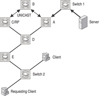
Figure 22.4: Requesting a multicast stream.
-
The source, a Windows Media server, sends packets containing streaming content and a multicast group address.
-
Switch 1 uses IGMP traffic snooping to read the IP header of multicast packets. Because the packets do not contain an IGMP message and no IGMP requests have been received from other ports for the multicast, the switch sends the multicast traffic to the router A serial port only. Without IGMP traffic snooping, the switch would flood multicast traffic to all ports. Notice that the source does not join a multicast group or even communicate with any external network device in sparse mode.
-
Router A becomes aware that the multicast packets from switch 1 contain a multicast group address assigned to the RP. It was already aware of the RP after router C was statically configured.
-
Router A forwards a PIM-SMv2 Register packet to the RP. The Register packet is a multicast packet encapsulated in a unicast packet. Because it is sent via unicast, the packet will contain the IP address of the router A interface, and router A will receive acknowledgement of its receipt by the RP.
-
When the RP receives the message, it extracts the multicast packet. At this point, no downstream clients have requested the stream, so the RP sends a Register stop message to router A. The RP does nothing further until a join request comes from a client.
All routers, including the RP, maintain an outgoing interface list (oilist) that contains those interfaces that have received requests for traffic from a multicast group. At this point, there are no entries in the oilist.
-
Router A receives the Register stop message and does not route the multicast packets.
The two pieces of information a router or client can use to locate a multicast group are the source IP address and the multicast group address, often seen in the form (S,G). If dense mode is used, all routers and clients need to send and maintain (S,G) state information. In a sparse mode shared tree, the client and all routers except the RP need only maintain group address state information or (*,G). At this point, the RP has (S,G) information, but no multicast packets will be forwarded until a client makes a request to join the group.
The process shown in figure 22.5 describes what happens when a client requests a multicast stream.
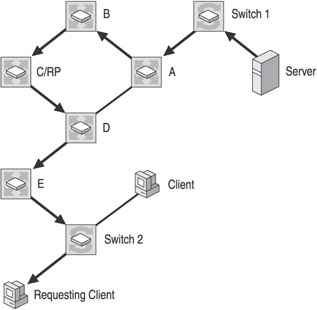
Figure 22.5: A client requests a multicast stream.
-
When the client requests a multicast stream, it sends an IGMP membership report containing only the multicast group address (*,G).
-
Switch 2 uses IGMP traffic snooping to map the traffic to the client port only, and it sends the IGMP membership report on to router E.
-
Router E is aware of the RP and the multicast groups the RP handles, so router E adds the request to its oilist and sends a join request upstream toward the RP.
-
Router D receives the request, adds the request to its oilist, and passes it on to router C, the RP.
-
Router C adds the request to its oilist, and then forwards the multicast packets on the shared tree toward router E. Remember, the register process gave the RP awareness of the location of the source.
-
With the addition of the join request to its oilist, router A has state for the multicast group, and begins forwarding the multicast packets through the routers to the client.
-
In addition to the multicast packets, router E receives the source address from the RP and begins rerouting the multicast stream through the most direct route back to the source. The shared tree path is not always the shortest path back to the source, and is, therefore, not the most efficient use of network resources and bandwidth. A shorter path provides less latency and a higher-quality end user experience. PIM-SMv2 solves this problem by providing a system for routers to automatically switch over from the shared tree to the shortest path tree (SPT). In SPT switchover, a leaf router uses the source address to locate the most the direct route. If the RP is the most direct route, it takes no action. In this scenario, however, router D locates a more direct route to router A, as illustrated in figure 22.6.
Figure 22.6: Locating the shortest path tree in a multicast network. -
After router D switches, it sends a prune message back to the RP. With no clients requesting the multicast group, the path from router D through the RP is removed, along with the entries in the oilists of the associated routers.
-
Router E forwards the stream to switch 2, which has been configured by the IGMP membership report to map the stream only to the client port that requested the stream.
-
The client receives the stream and begins rendering the packets.
When a client stops a multicast stream, the following messages are sent:
-
The client sends an IGMP leave group message.
-
Switch 2 stops multicast packets from being forwarded to the client port and passes the IGMP leave message to router E.
-
All routers prune their downstream paths and forward the message upstream, removing the request from their oilists. As long as the source continues streaming, packets will appear at the router A interface leading to the source, but they will not be forwarded until another join request is received.
Source-Specific Multicasting
The Fabrikam network will be configured for PIM-SMv2. However, there is an improved system called PIM Source-Specific Multicast (PIM-SSM), to which Fabrikam can upgrade later. Most enterprises use PIM-SMv2, and more support is available for it. However, Windows Media 9 Series supports PIM-SSM, and it is becoming increasingly available for most routers.
PIM-SSM simplifies the multicast process and provides a better experience for end users. Basically, instead of going through an RP and receiving a stream over a shared tree, the client is aware of the source IP address and sends an IGMPv3 membership report that contains (S,G) information. The SSM-enabled leaf routers then initiate a process that builds a shortest path tree (SPT). PIM-SSM uses the PIM-SMv2 functionality to create the SPT without an RP. There is no longer the notion of an RP and all the messages and procedures associated with it. With PIM-SSM, the path between client and source is known as a channel.
The following steps outline the PIM-SSM process using the network in the previous figures:
-
The client initiates the process by sending an IGMPv3 Membership Report to router E. Note that the switch performs IGMP traffic snooping as with PIM-SM. In IGMPv3, the report contains the source address as well as the multicast group address.
-
Router E uses the source address to locate and forward a join message to router A directly.
-
The message initiates the building of a source tree. In an actual network, there may be a number of routers between the client and source. Each receives the join message and maintains an (S,G) state.
-
Multicast packets are forwarded from the source to the client.
A disadvantage of PIM-SSM is that a network may not be fully enabled. Routers need to be upgraded to handle PIM-SSM and IGMPv3, and switches, clients, and sources need to be able to create and read IGMPv3 messages. Attempting to deploy a system that contained a mixture of PIM-SM and PIM-SSM multicast traffic would probably lead to confusion and errors.
EAN: 2147483647
Pages: 258