9.5 Treatment of B-pictures
9.5 Treatment of B-pictures
B-pictures play an important role in low bit rate applications. If they are coded at lower quality, the quantisation distortion is not accumulated (since they are not used for prediction, see section 7.6). This is not the case for P-pictures, where any gain in reducing the bits in one frame may have to be returned at a higher cost later, when the distortion accumulates in a noise-like signal, which is difficult to code. For very low bit rate video, such as video for mobile networks, normally the frame rate is low (e.g. 5–10 frames/s), and hence the number of B-pictures between the anchor P and I-pictures cannot be large. Apparently only one B-picture is an ideal choice. Also, in these applications I-pictures are hardly used, or if they are used, the GOP length is normally very large. Hence it is plausible to assume, if there is any B-picture in a video, that it is accompanied by a neighbouring P-picture. Thus one can nearly always code B-pictures in relation to the P-picture counterpart, and interrelate their addressing. Two of these are used as annexes in the H.263 family, and will be discussed in the following.
9.5.1 PB frames mode
A PB frame consists of two P and B-pictures coded as one unit [25-G]. The P-picture is predicted from the last decoded P-picture and the B-picture is predicted both from the last decoded P-picture and the P-picture currently being decoded. The prediction process is illustrated in Figure 9.16.
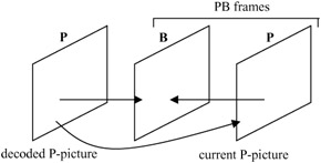
Figure 9.16: Prediction in PB frames mode
9.5.1.1 Macroblock type
Since in the PB frames mode a unit of coding is a combined macroblock from P and B-pictures, the composite macroblock comprises 12 blocks. First, the data for the six P-blocks is transmitted as the default H.263 mode then the data for the six B-blocks. The composite macroblock may have various combinations of coding status for the P-and B-blocks, which are dictated by the combined macroblock block pattern MCBPC. One of the modes of the MCBPC is the intra macroblock type that has the following meaning:
-
the p-blocks are intra coded
-
the B-blocks are inter coded with prediction as for an inter block.
The motion vector data (MVD) is also included for intra blocks in pictures for which the type information PTYPE indicates inter. In this case the vector is used for the B-block only. The codewords MVD2-4 are never used for intra. The candidate motion vector predictor is not set to zero if the corresponding macroblock was coded in intra mode.
9.5.1.2 Motion vectors for B-pictures in PB frames
In the PB frames mode, the motion vectors for the B-pictures are calculated as follows. Assume we have a motion vector component MV in half pixel units to be used in the P-pictures. This MV represents a vector component for an 8 × 8 luminance block. If only one motion vector per macroblock is transmitted, then MV has the same value for each of the 8 × 8 luminance blocks.
For prediction of the B-picture we need both forward and backward vector components MVF and MVB. Assume also that MVD is the delta vector component given by the motion vector data of a B-picture (MVDB) and corresponds to the vector component MV. Now MVF and MVB are given in half pixel units by the following formulae:
| (9.8) | 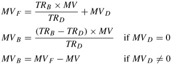 |
Here TRD is the increment of temporal reference TR from the last picture header. In the optional PB frames mode, TR only addresses P-pictures. TRB is the temporal reference for the B-pictures, which indicates the number of nontransmitted pictures since the last P or I-picture and before the B-picture.
Division is done by truncation and it is assumed that the scaling reflects the actual position in time of P and B-pictures. Care is also taken that the range of MVF should be constrained. Each variable length code for MVDB represents a pair of difference values. Only one of the pairs will yield a value for MVF falling within the permitted range of -16 to +15.5. The above relations between MVF, MVB and MV are also used in the case of intra blocks, where the vector is used for predicting B-blocks.
For chrominance blocks, the forward and backward motion vectors, MVF and MVB, are derived by calculating the sum of the four corresponding luminance vectors and dividing this sum by 8. The resulting one-sixteenth pixel resolution vectors are modified towards the nearest half pixel position.
9.5.1.3 Prediction for a B-block in PB frames
In PB frames mode, predictions for the 8 × 8 pixel B-blocks are related to the blocks in the corresponding P macroblock. First, it is assumed that the forward and backward motion vectors MVF and MVB are calculated. Secondly, it is assumed that the luminance and chrominance blocks of the corresponding P-macroblock are decoded and reconstructed. This macroblock is called PREC. Based on PREC and its prediction, the prediction for the B-block is calculated.
The prediction of the B-block has two modes that are used for different parts of the block:
-
For pixels where the backward motion vector MVB points to inside PREC, use bidirectional prediction. This is obtained as the average of the forward prediction using MVF relative to the previously decoded P-picture, and the backward prediction using MVB relative to PREC. The average is calculated by dividing the sum of the two predictions by two with truncation.
-
For all other pixels, forward prediction using MVF relative to the previously decoded P-picture is used.
Figure 9.17 shows forward and bidirectionally predicted B-blocks. Part of the block that is predicted bidirectionally is shaded and the part that uses forward prediction only is shown unshaded.
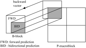
Figure 9.17: Forward and bidirectional prediction for a B-block
9.5.2 Improved PB frames
This mode is an improved version of the optional PB frames mode of H.263 [25-M]. Most parts of this mode are similar to the PB frames mode, the main difference being that in the improved PB frames mode, the B part of the composite PB-macroblock, known as the BPB-macroblock, may have a separate motion vector for forward and backward prediction. This is in addition to the bidirectional prediction mode that is also used in the normal PB frames mode.
Hence there are three different ways of coding a BPB-macroblock and the coding type is signalled by the MVDB parameter. The BPB-macroblock coding modes are:
-
Bidirectional prediction: in the bidirectional prediction mode, prediction uses the reference pictures before and after the BPB-picture. These references are the P-picture part of the temporally previous improved PB frames and the P-picture part of the current improved PB frame. This prediction is equivalent to the prediction in normal PB frames mode when MVD = 0. Note that in this mode the motion vector data (MVD) of the PB macroblock must be included if the P macroblock is intra coded.
-
Forward prediction: in the forward prediction mode the vector data contained in MVDB are used for forward prediction from the previous reference picture (an intra or inter picture, or the P-picture part of PB or improved PB frames). This means that there is always only one 16 × 16 vector for the BPB-macroblock in this prediction mode. A simple prediction is used for coding of the forward motion vector. The rule for this predictor is that if the current macroblock is not at the far left edge of the current picture or slice and the macroblock to the left has a forward motion vector, then the predictor of the forward motion vector for the current macroblock is set to the value of the forward motion vector of the block to the left; otherwise the predictor is set to zero. The difference between the predictor and the desired motion vector is then VLC coded in the same way as vector data to be used for the P-picture (MVD).
-
Backward prediction: in the backward prediction mode the prediction of the BPB-macroblock is identical to BREC of normal PB frames mode. No motion vector data is used for the backward prediction.
9.5.3 Quantisation of B-pictures
In normal mode the quantisation parameter quant is used for each macroblock of P and B-pictures. In PB frames mode, quant is used for P-blocks only, while for the B-blocks a different quantisation parameter bquant is used. In the header information a relative quantisation parameter known as dbquant is sent which indicates the relation between quant and bquant, as defined in Table 9.2.
| dbquant | bquant |
|---|---|
| 00 | (5 × quant)/4 |
| 01 | (6 × quant)/4 |
| 10 | (7 × quant)/4 |
| 11 | (8 × quant)/4 |
Division is done by truncation, and bquant ranges from 1 to 31. If the range exceeds these values they are clipped to their limits. Note that since dbquant is a two-bit codeword whereas quantisation information, such as quant, is a five-bit word (indicating quantisation parameters in the range of 1 to 31), such a strategy significantly reduces the overhead information.
EAN: 2147483647
Pages: 148
- Using SQL Data Definition Language (DDL) to Create Data Tables and Other Database Objects
- Performing Multiple-table Queries and Creating SQL Data Views
- Working with Comparison Predicates and Grouped Queries
- Working with SQL JOIN Statements and Other Multiple-table Queries
- Monitoring and Enhancing MS-SQL Server Performance