9.1 How does H.263 differ from H.261 and MPEG-1?
9.1 How does H.263 differ from H.261 and MPEG-1?
The source encoder of H.263 follows the general structure of the generic DCT-based interframe coding technique used in the H.261 and MPEG-1 codecs (see Figure 3.18). The core H.263 employs a hybrid interpicture prediction to utilise temporal redundancy and transform coding of the residual signal to reduce spatial redundancy. The decoder has motion compensation capability, allowing optional incorporation of this technique at the encoder. Half pixel precision is used for the motion compensation, as opposed to the optional full pixel precision and loop filter used in Recommendation H.261. In the new versions of H.263, use of quarter and even one eighth of pixel precision are recommended [6].
Perhaps the most significant differences between the core H.263 and H.261/MPEG-1 are in the coding of the transform coefficients and motion vectors. In the following sections these and some other notable differences such as the additional optional modes are explained.
9.1.1 Coding of H.263 coefficients
In H.261 and MPEG-1, we saw that the transform coefficients are converted via a zigzag scanning process into two-dimensional, run and index events (see section 6.4). In H.263 these coefficients are represented as a three-dimensional event of (last, run, level). Similar to the two-dimensional event, the run indicates the number of zero-valued coefficients preceding a nonzero coefficient in the zigzag scan, and level is the normalised magnitude of the nonzero coefficient which is sometimes called index. last is a new variable to replace the end of block (EOB) code of H.261 and MPEG-1. last takes only two values, 0 and 1. last 0 means that there are more nonzero coefficients in the block, and 1 means that this is the last nonzero coefficient in the block.
The most likely events of (last, run, level) are then variable length coded. The remaining combinations of (last, run, level) are coded with a fixed 22-bit word consisting of seven bits escape, one bit last, six bits run and eight bits level.
9.1.2 Coding of motion vectors
The motion compensation in the core H.263 is based on one motion vector per macroblock of 16 × 16 pixels, with half pixel precision. The macroblock motion vector is then differentially coded with predictions taken from three surrounding macroblocks, as indicated in Figure 9.1. The predictors are calculated separately for the horizontal and vertical components of the motion vectors MV1, MV2 and MV3. For each component, the predictor is the median [1] value of the three candidate predictors for this component:
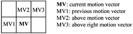
Figure 9.1: Motion vector prediction
| (9.1) | 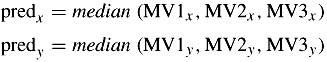 |
The difference between the components of the current motion vector and their predictions are variable length coded. The vector differences are defined by:
| (9.2) | 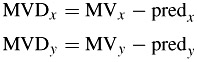 |
In the special cases at the borders of the current group of blocks (GOB) or picture, the following decision rules are applied in order as follows:
-
The candidate predictor MV1 is set to zero if the corresponding macroblock is outside the picture at the left side (Figure 9.2a).
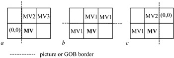
Figure 9.2: Motion vector prediction for the border macroblocks -
The candidate predictors MV2 and MV3 are set to MV1 if the corresponding macroblocks are outside the picture at the top, or if the GOB header of the current GOB is nonempty (Figure 9.2b).
-
The candidate predictor MV3 is set to zero if the corresponding macroblock is outside the picture at the right side (Figure 9.2c).
-
When the corresponding macroblock is coded intra or is not coded, the candidate predictor is set to zero.
The values of the difference components are limited to the range [-16 to 15.5]. Since, in H.263, the source images are of the CIF family with the 4:2:0 format, each macroblock comprises four luminance and two chrominance components, Cb and Cr. Hence the motion vector of the macroblock is used for all four luminance blocks in the macroblock. Motion vectors for both chrominance blocks are derived by dividing the component values of the macroblock vector by two, due to the lower chrominance resolution. The resulting values of the quarter pixel resolution vectors are modified towards the nearest half pixel position (note: the macroblock motion vector has half pixel resolution).
9.1.3 Source pictures
The source encoder operates on noninterlaced pictures at approximately 29.97 frames per second. These pictures can be one of the five standard picture formats of the CIF family: subQCIF, QCIF, CIF, 4CIF and 16CIF. Since in CIF the luminance and chrominance sampling format is 4:2:0, then for either of these pictures, the horizontal and vertical resolutions of the chrominance components are half the luminance. Table 9.1 summarises pixel resolutions of the CIF family used in H.263.
| Picture format | Number of pixels for luminance per line | Number of lines for luminance per picture | Number of pixels for chrominance per line | Number of lines for chrominance per picture |
|---|---|---|---|---|
| SubQCIF | 128 | 96 | 64 | 48 |
| QCIF | 176 | 144 | 88 | 72 |
| CIF | 352 | 288 | 176 | 144 |
| 4CIF | 704 | 576 | 352 | 288 |
| 16CIF | 1408 | 1152 | 704 | 576 |
Each picture is divided into a group of blocks (GOBs). A GOB comprises k × 16 lines, depending on the picture format (k = 1 for subQCIF, QCIF and CIF; k = 2 for 4CIF; k = 4 for 16CIF). The number of GOBs per picture is six for subQCIF, nine for QCIF, and 18 for CIF, 4CIF and 16CIF. Each GOB is divided into 16 × 16 pixel macroblocks, of which there are four luminance and one each of chrominance blocks of 8 x 8 pixels.
9.1.4 Picture layer
The picture layer contains the picture header, the GOB header together with various coding decisions on macroblocks in a GOB and finally the coded transform coefficients, which are also used in H.261 and MPEG-1 and 2. The most notable difference in the header information for H.263 is in the type information, called PTYPE. For the first generation of H.263, this is a 13-bit code that gives information about the complete picture, in the form of [1]:
| bit 1 | always 1, in order to avoid start code emulation |
| bit 2 | always 0, for distinction with H.261 |
| bit 3 | split screen indicator, 0 off, 1 on |
| bit 4 | document camera indicator, 0 off, 1 on |
| bit 5 | freeze picture release, 0 off, 1 on |
| bit 6–8 | source format, 000 forbidden, 001 subQCIF, 010 QCIF, 011 CIF, 100 4CIF, 101 16CIF, 110 reserved, 111 extended PTYPE |
| bit 9 | picture coding type, 0 intra, 1 inter |
| bit 10 | optional unrestricted motion vector mode, 0 off, 1 on |
| bit 11 | optional syntax-based arithmetic coding mode, 0 off, 1 on |
| bit 12 | optional advanced prediction mode, 0 off, 1 on |
| bit 13 | optional PB frame mode, 0 normal picture, 1 PB frame |
The split screen indicator is a signal that indicates that the upper and lower half of the decoded picture could be displayed side by side. This has no direct effect on the encoding and decoding of the picture.
The freeze picture release is a signal from an encoder which responds to a request for packet retransmission (if not acknowledged) or fast update request, and allows a decoder to exit from its freeze picture mode and display decoded picture in the normal manner.
Bits 10–13 refer to the early four optional modes of H.263. Since 1995 more options as annexes have then been added to the extensions of this codec. These optional modes are activated when bits 6–8 of the PTYPE header are in the extended mode of 111, and necessarily some additional bits define the new options. Hence extensions of H.263 have a longer PTYPE header and also a different picture layer than the above 13 bits. All these optional modes are only used after negotiation between the encoder and the decoder via the control protocol Recommendation H.245 [9].
Also for further reduction in the overhead, the code for macroblock type and coded block pattern are combined. For example, the combined code of macroblock type and coded block pattern is called MCBPC. MCBPC is always present for each macroblock, irrespective of its type and the options used. Note that in H.261, the MPEG-1 and 2 code block pattern is defined separately from the macroblock type.
[1]To find the median value, the components are rank ordered and the middle value is chosen.
EAN: 2147483647
Pages: 148