4.7 Embedded block coding with optimised truncation (EBCOT)
4.7 Embedded block coding with optimised truncation (EBCOT)
Embedded block coding with optimised truncation EBCOT [17] is another wavelet-based coding algorithm that has the capability of embedding many advanced features in a single bit stream while exhibiting state-of-the-art compression performance. Due to its rich set of features, modest implementation complexity and excellent compression performance, the EBCOT algorithm has been adopted in the evolving new still image coding standard, under the name of JPEG2000. Thus, because of the important role of EBCOT in the JPEG2000 standard, we describe this coding technique in some detail. Before describing this new method of wavelet coding, let us investigate the problem with EZW and SPIHT that caused their rejection for JPEG2000.
As we will see in Chapter 5, spatial and SNR scalability of images are among the many requirements from the JPEG2000 standard. Spatial scalability means, from the compressed bit stream, to be able to decode pictures of various spatial resolutions. This is in fact an inherent property of the wavelet transform, irrespective of how the wavelet coefficients are coded, since at any level of the decomposition the lowest band of that level gives a smaller replica of the original picture. The SNR scalability means, from the compressed bit stream, to be able to decode pictures of various qualities. In both EZW and SPIHT, this is achieved by successive approximation or bit plane encoding of the wavelet coefficients. Thus it appears that EZW and SPIHT coding of the wavelet coded images can meet these two scalability requirements. However, the bit streams of both EZW and SPIHT inherently offer only SNR scalability. If spatial scalability is required, then the bit stream should be modified accordingly, which is then not SNR scalable. This is because the zero tree-based structure used in these methods involves downward dependencies between the subbands produced by the successive wavelet decompositions. These dependencies interfere with the resolution scalability. Moreover, the interband dependency by the use of zero tree structure causes the error to propagate through the bands. This again does not meet the error resilience requirement of JPEG2000.
These shortfalls can be overcome if each subband is coded independently. Even to make coding more flexible, subband samples can be partitioned into small blocks with each block coded independently. The dependencies may exist within a block but not between different blocks. The size of the blocks determines the degree to which one is prepared to sacrifice coding efficiency in exchange for flexibility in the ordering of information within the final compressed bit stream. The independent block coding paradigm is the heart of EBCOT. This independent coding allows local processing of the samples in each block, which is advantageous for hardware implementation. It also makes highly parallel implementation possible, where multiple blocks are encoded and decoded simultaneously. More importantly, due to flexibility in the rearrangement of bits in the EBCOT, simultaneous SNR and spatial scalability is possible. Obviously, the error encountered in any block's bit stream will clearly have no influence on other blocks and hence improves the robustness. Finally, since unlike EZW and SPHIT similarities between the bands are not exploited, there is small deficiency in the compression performance. This is compensated for by the use of more efficient context-based arithmetic coding and the post compression rate distortion (PCRD) optimisation.
In EBCOT, each subband is partitioned into relatively small block of samples, called code blocks. Typical code block size is either 32 × 32 or 64 × 64 and each code block is coded independently. The actual coding algorithm in EBCOT can be divided into three stages:
-
bit plane quantisation
-
binary arithmetic coding (tier 1 coding)
-
bit stream organisation (tier 2 coding).
Each of these steps is described briefly in the following subsections.
4.7.1 Bit plane quantisation
All code blocks of a subband use the same quantiser. The basic quantiser step size ∆b of a subband b is selected based on either perceptual importance of the subband or rate control. The quantiser maps the magnitude of a wavelet coefficient to a quantised index, as shown in Figure 4.14, keeping its sign. It has uniform characteristics (equal step size) with a dead zone of twice the step size.
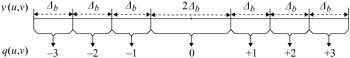
Figure 4.14: Uniform dead zone quantiser with step size ∆b
In bit plane coding, the quantiser index is encoded one bit at a time, starting from the most significant bit (MSB) and preceding to the least significant bit (LSB). If K is the sufficient number of bits to represent any quantisation index in a code block, then the maximum coefficient magnitude will be ∆b(2K - 1). An embedded bit stream for each code block is formed by first coding the most significant bit, i.e. (K - 1)th bit together with the sign of any significant sample for all the samples in the code block. Then the next most significant bit, i.e. (K - 2)th bit, is coded until all the bit planes are encoded. If the bit stream is truncated then some or all of the samples in the block may be missing one or more least significant bits. This is equivalent to having used a coarser dead zone quantiser with step size ∆b2P, where p is the index of the last available bit plane for the relevant sample or p least significant bits of quantiser index still remain to be encoded.
4.7.2 Conditional arithmetic coding of bit planes (tier 1 coding)
During progressive bit plane coding, substantial redundancies exist between the successive bit planes. The EBCOT algorithm has exploited these redundancies in two ways. The first is to identify whether a coefficient should be coded, and the second how best the entropy coding can be adapted to the statistics of the neighbouring coefficients. Both of these goals are achieved through the introduction of the binary significance state σ, which is defined to signify the importance of each coefficient in a code block. At the beginning of the coding process, the significant states of all the samples in the code block are initialised to 0 and then changed to 1 immediately after coding the first nonzero magnitude bit for the sample. Since the neighbouring coefficients generally have similar significance resulting in clusters of similar binary symbols in a plane, then the significance state, σ, is a good indicator for a bit plane of a coefficient to be a candidate for coding.
Also, in EBCOT, adaptive binary arithmetic is used for entropy coding of each symbol. Again, the clustering of significance of neighbours can be exploited to adapt the probability model, based on the significance states of its immediate neighbours. This is called context-based binary arithmetic coding, where the probability assigned to code a binary symbol of 0 or 1 or the positive/negative sign of a coefficient, is derived from the context of its eight immediate neighbours, shown in Figure 4.15.
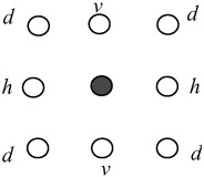
Figure 4.15: Eight immediate neighbouring symbols
In general, the eight immediate neighbours can have 256 different contextual states, or as many contextual states for the positive and negative signs. In EBCOT, the probability models used by the arithmetic coder are limited within 18 different contexts: nine for the significance propagation, one for run length, five for sign coding and three for refinement. These contexts are explained in the relevant parts.
Since the status of the eight immediate neighbours affects the formation of the probability model, the way coefficients in a code block are scanned should be defined. In the JPEG2000 standard, in every bit plane of a code block, the coefficients are visited in a stripe scan order with a height of four pixels, as shown in Figure 4.16.
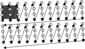
Figure 4.16: Stripe scanned order in a code block
Starting from the top left, the first four bits of the first column are scanned. Then the four bits of the second column, until the width of the code block is covered. Then the second four bits of the first column of the next stripe are scanned and so on. The stripe height of four has been chosen to facilitate hardware and software implementations.
4.7.3 Fractional bit plane coding
The quantised coefficients in a code block are bit plane encoded independent of other code blocks in the subbands. Instead of encoding the entire bit plane in one pass, each bit plane is encoded in three subbit plane passes, called fractional bit plane coding. The reason for this is to be able to truncate the bit stream at the end of each pass to create a near optimum bit stream. This is also known as post compression rate distortion (PCRD) optimisation [18]. Here, the pass that results in the largest reduction in distortion for the smallest increase in bit rate is encoded first.
The goal and benefits of fractional bit plane coding can be understood with the help of Figure 4.17. Suppose (R1, D1) and (R2, D2) are the rate distortion pairs corresponding to two adjacent bit planes p1 and p2. Also, assume during the encoding of each pass that the increase in bit rate and reduction in distortion follow the characteristics identified by labels A, B and C. As we see, in coding the whole bit plane, that is going from point X1 to point X2, no matter which route is followed, the ultimate bit rate is increased from R1 to R2, and the distortion is reduced from D1 to D2. But if due to the limit in the bit rate budget, the bit rate has to be truncated between R1 and R2, R1 ≤ R ≤ R2, then it is better to follow the passes in the sequence ABC rather than CBA.
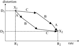
Figure 4.17: The impact of order of fractional bit plane coding in distortion reduction
This sort of fractional bit plane coding is in fact a method of optimising the rate distortion curve, with the aim of generating a finely embedded bit stream, which is known as post compression rate distortion (PCRD) optimisation in EBCOT [18]. Figure 4.18 compares the optimised rate distortion associated with the fractional bit plane encoding versus that of the conventional bit plane encoding. The solid dots represent the rate distortion pairs at the end of each biplane, and the solid line is the rate distortion curve that one could expect to obtain by truncating the bit stream produced by this method to an arbitrary bit rate. On the other hand, the end points associated with each pass of the fractional bit plane coding are shown with blank circles and the broken line illustrates its rate distortion curve. Since initial coding passes generally have steeper rate distortion slopes, the end point for each coding pass lies below the convex interpolation of the bit plane termination point. Thus fractional bit plane encoding results in a near optimum coding performance compared with simple bit plane coding.
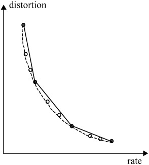
Figure 4.18: Rate distortion with optimum trunctaion
Generally, in coding a coefficient the largest reduction in distortion occurs when the coefficient is insignificant, but it is more likely to become significant during the coding. Moderate reduction in distortion is when the coefficient is already significant and the coding refines it. Finally, the least reduction in distortion is when the insignificant coefficient after the encoding is likely to remain insignificant. These are in fact the remaining coefficients not coded in the two previous cases. Thus it is reasonable to divide bit plane encoding into three passes, and encode each pass in the above encoding order. In JPEG2000, the fractional bit plane is carried out in three passes. The roles played by each encoding pass, and their order of significance in generating an optimum bit stream, are given below.
4.7.3.1 Significance propagation pass
This is the first pass of the fractional bit plane encoding that gives the largest reduction in the encoding distortion. In this pass, the bit of a coefficient in a given bit plane is encoded, if and only if, prior to this pass, the state of the coefficient was insignificant but at least one of its eight immediate neighbours had significant states. If the coefficient is to be coded, the magnitude of its bit, 0 or 1, is arithmetically coded with a derived probability model from the context of its eight immediate neighbours, shown in Figure 4.15. The probability assigned to bit 0 is complementary to the probability assigned to bit 1. The context selection is based upon the significance of the sample's eight immediate neighbours, which are grouped in three categories.
| (4.30) | 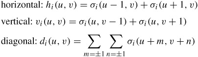 |
where hi(u, v), vi(u, v) and di(u, v) are the horizontal, vertical and diagonal neighbours, for the ith coefficient at coordinates (u, v), and σi (u, v) is the significance state of a coefficient at those coordinates. Neighbours that lie outside the code block are interpreted as insignificant for the purpose of constructing these three quantities. To optimise both the model adaptations of cost and implementation complexity, 256 possible neighbourhood configurations are mapped to nine distinct coding contexts based on eqn. 4.30, as shown in Table 4.4.
| LL, LH and HL bands | HH band | |||||
|---|---|---|---|---|---|---|
| hi(u, v) | vi(u, v) | di(u, v) | context | di(u, v) | hi(u, v) + vi(u, v) | context |
| 0 | 0 | 0 | 0 | 0 | 0 | 0 |
| 0 | 0 | 1 | 1 | 0 | 1 | 1 |
| 0 | 0 | >1 | 2 | 0 | >1 | 2 |
| 0 | 1 | X | 3 | 1 | 0 | 3 |
| 0 | 2 | X | 4 | 1 | 1 | 4 |
| 1 | 0 | 0 | 5 | 1 | >1 | 5 |
| 1 | 0 | >0 | 6 | 2 | 0 | 6 |
| 1 | >0 | X | 7 | 2 | >0 | 7 |
| 2 | X | X | 8 | >2 | X | 8 |
To make identical context assignment for LH and HL bands, the code blocks of HL subbands are transposed before the coding. The LH subband responds most strongly to horizontal edges in the original image, so the context mapping gives more emphasis on the horizontal neighbours.
Note that the significance propagation pass includes only those bits of coefficients that were insignificant before this pass and have a nonzero context. If the bit of the coefficient is 1 (the coefficient becomes significant for the first time), then its state of significance, σ, is changed to 1, to affect the context of its following neighbours. Thus the significance of states of coefficients propagates throughout the coding, and hence the name given to this pass is the significance propagation pass. Note also that if a sample is located at the boundary of a block, then only the available immediate neighbours are considered and the significance state of the missing neighbours are assumed to be zero.
Finally, if a coefficient is found to be significant, its sign is also arithmetically coded. Since the sign bits from the adjacent samples exhibit substantial statistical dependencies, they can be effectively exploited to improve the arithmetic coding efficiency. For example, the wavelet coefficients of horizontal and vertical edges are likely to be of the same polarity. Those after and before the edge are of mainly opposite polarity. In the EBCOT algorithm, the arithmetic coding of a sign bit employs five contexts. Context design is based upon the relevant sample's immediate horizontal and vertical neighbours, each of which may be in one of the three states: significant and positive, significant and negative, insignificant. There are thus 34 = 81 unique neighbourhood configurations. The details of the symmetry configurations and approximations to map these 81 configurations to one of the five context levels can be found in [18].
4.7.3.2 Magnitude refinement pass
The magnitude refinement pass is the second most efficient encoding pass. During this pass, the magnitude bit of a coefficient that has already become significant in a previous bit plane is arithmetically coded. The magnitude refinement pass includes the bits from the coefficients that are already significant, except those that have just become significant in the immediately preceding significance propagation pass. There are three contexts for the arithmetic coder, which are derived from the summation of the significance states of the horizontal, vertical and diagonal neighbours. These are the states as currently known to the decoder and not the states used before the significance decoding pass. Further, it is dependent on whether this is the first refinement bit (the bit immediately after the significance and sign bits) or not.
In general, the refinement bits have an even distribution, unless the coefficient has just become significant in the previous bit plane (i.e. the magnitude bit to be encoded is the first refinement bit). This condition is first tested and, if it is satisfied, the magnitude bit is encoded using two contexts, based on the significance of the eight immediate neighbours (see Figure 4.15). Otherwise, it is coded with a single context regardless of the neighbouring values.
4.7.3.3 Clean up pass
All the bits not encoded during the significance propagation and refinement passes are encoded in the clean up pass. That is the coefficients that are insignificant and had the context value of zero (none of the eight immediate neighbours was significant) during the significance propagation pass. Generally, the coefficients coded in this pass have a very small probability of being significant and hence are expected to remain insignificant. Therefore, a special mode, called the run mode, is used to aggregate the coefficients of remaining insignificance. A run mode is entered if all the four samples in a vertical column of the stripe of Figure 4.16 have insignificant neighbours. Specifically, run mode is executed when each of the following conditions holds:
-
four consecutive samples must all be insignificant, i.e. σi (u + m, v) = 0, for 0 ≤ m ≤ 3
-
the samples must have insignificant neighbours, i.e. hi(u + m, v) = vi (u + m, v) = di(u + m, v) = 0, for 0 ≤ m ≤ 3
-
samples must reside within the same subblock
-
the horizontal index of the first sample, u, must be even.
In the run mode a binary symbol is arithmetically coded with a single context to specify whether all four samples in the vertical column remain insignificant. Symbol 0 implies that all the four samples are insignificant and symbol 1 implies that at least one of four samples becomes significant in the current bit plane. If the symbol is 1, then two additional arithmetically coded bits are used to specify the location of the first nonzero coefficient in the vertical column.
Since it is equally likely that any one of the four samples in the column is the first nonzero sample, then the arithmetic coding uses a uniform context. Thus run mode has a negligible role in coding efficiency. It is primarily used to improve the throughput of the arithmetic encoder through symbol aggregation.
After specifying the position of the first nonzero symbol in the run, the remaining samples in the vertical column are coded in the same manner as in the significance propagation pass and use the same nine contexts. Similarly, if at least one of the four coefficients in the vertical column has a significant neighbour, the run mode is disabled and all the coefficients in that column are again coded with the procedure used for the significance propagation pass.
For each code block, the number of MSB planes that are entirely zero is signalled in the bit stream. Since the significance state of all the coefficients in the first nonzero MSB is zero, this plane only uses the clean up pass and the other two passes are not used.
Example
In order to show how the wavelet coefficients in a fractional bit plane are coded, Figure 4.19 illustrates a graphical demonstration of step-by-step encoding from bit plane to bit plane and pass to pass.
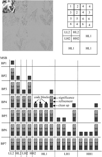
Figure 4.19: An illustration of fractional bit plane encoding
The Barbara image of size 256 x 256 pixels with two levels of wavelet decomposition generates seven subimages, as shown in Figure 4.19. Except for the lowest band, the magnitudes of all the other bands are magnified by a factor of four, for better illustration of image details. The code block size is assumed to be a square array of 64 x 64 coefficients. Hence, every high frequency band of LH1, HL1 and HH1 is coded in four code blocks, and the remaining bands of LL2, LH2, HL2 and HH2 in one code block each. That is, the whole image is coded in 16 code blocks. The bit streams generated by each pass in every bit plane are also shown in square boxes with different textures.
Before the coding starts, the significance states of all the code blocks are initialised to zero. For each code block the encoding starts from the most significant bit plane. Since the LL2 band has a higher energy (larger wavelet coefficients) than the other bands, in this example only some of the MSB of the code block of this band are significant at the first scanned bit plane, PB1. In this bit plane the MSB of none of the other code blocks is significant (they are entirely zero), and are not coded at all.
Since the code block of LL2 band in BP1 is coded for the first time (the significant states of all the coefficients are initialised to zero), then the MSB bit of every coefficient has a nonsignificant neighbour and hence cannot be coded at the significance propagation pass. Also, none of the bits are coded at the refinement pass, because these coefficients had not been coded in the previous bit plane. Therefore, all the bits are left to be coded in the clean up pass, and they constitute the bit stream of this pass.
At the second bit plane, BP2, some of the coefficients in the HL2 and HH2 code blocks become significant for the first time. Hence, as was explained earlier, they are coded only at the clean up pass, as shown in the Figure. For the code block of LL2, since the coefficients with significant magnitudes of this code block have already been coded at the clean up pass of BP1, the block uses all the three passes. Those coefficients of the bit plane BP2 with insignificant states that have at least one state significant immediate neighbour are coded with the significance propagation pass. The state significant coefficients are now refined in the refinement pass. The remaining coefficients are coded at the clean up pass. Other code blocks in this bit plane are not coded at all.
At the third bit plane, BP3, some of the coefficients of the code block of subband LH2 and those of the code block of subband HL1 become significant for the first time, hence they are coded only in the clean up pass. The code blocks of LL2, HL2 and HH2 are now coded at the three passes. The remaining code blocks are not coded at all. The bit plane numbers of those code blocks that are coded for the first time are also shown in the Figure with numbers from 1 to 6. As we see, after bit plane 7 all the code blocks of the bands are coded in all three passes.
4.7.4 Layer formation and bit stream organisation (tier 2 coding)
The arithmetic coding of the bit plane data is referred as tier 1 coding. The tier 1 coding generates a collection of bit streams with one independent embedded bit stream for each code block. The purpose of tier 2 coding is to multiplex the bit streams for transmission and to signal the ordering of the resulting coded bit plane pass in an efficient manner. The second tier coding process can be best viewed as a somewhat elaborated parser for recovering pointers to code block segments in the bit stream. It is this coding step which enables the bit stream to have SNR, spatial and arbitrary progression and scalability.
The compressed bit stream from each code block is distributed across one or more layers in the final compressed bit stream. Each layer represents a quality increment. The number of passes included in a specific layer may vary from one code block to another and is typically determined by the encoder as a result of PCRD optimisation. The quality layers provide the feature of SNR scalability of the final bit stream such that truncating the bit stream to any whole number of layers yields approximately an optimal rate distortion representation of the image. However, employing a large number of quality layers can minimise the approximation. On the other hand, more quality layers implies a large overhead as auxiliary information to identify the contribution made by each code block to each layer. When the number of layers is large, only a subset of the code blocks will contribute to any given layer, introducing substantial redundancy in this auxiliary information. This redundancy is exploited in tier 2 coding to efficiently code the auxiliary information for each quality layer.
4.7.5 Rate control
Rate control refers to the process of generating an optimal image for a bit rate and is strictly an encoder issue. In section 4.7.3 we introduced fractional bit plane coding as one of these methods. In [17], Taubman proposes an efficient rate control method for the EBCOT compression algorithm that achieves a desired rate in a single iteration with minimum distortion. This method is known as post compression rate distortion (PCRD) optimisation. A JPEG2000 encoder with several possible variations can also use this method.
In another form of PCRD, each subband is first quantised using a very fine step size, and the bit planes of the resulting code blocks are entropy coded (tier 1 coding). This typically generates more coding passes for each code block than will be eventually included in the final bit stream. Next, a Lagrangian R-D optimisation is performed to determine the number of coding passes from each code block that should be included in the final compressed bit stream to achieve the desired bit rate. If more than a single quality layer is desired, this process can be repeated at the end of each layer to determine the additional number of coding passes from each code block that need to be included in the next layer. The details of PCRD optimisation can be found in [18].
At the end of this Chapter, it is worth comparing the compression efficiency of the three methods of wavelet coding, namely: EZW, SPIHT and the EBCOT. Figure 4.20 shows the quality of the Lena image coded with these methods at various bit rates. As the Figure shows, EZW has the poorest performance of all. The SPIHT method, even without arithmetic coding, outperforms EZW by about 0.3–0.4 dB. Adding arithmetic coding into SPIHT improves the coding efficiency by another 0.3 dB. The EBCOT algorithm, adopted in the JPEG2000 standard, is as good as the best of SPIHT.
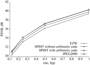
Figure 4.20: Compression performance of various wavelet coding algorithms
EAN: 2147483647
Pages: 148