4.4 Coding of the wavelet subimages
4.4 Coding of the wavelet subimages
The lowest band of the wavelet subimages is a replica of the original image, but at a much reduced size, as can be seen from Figure 4.10. Efficient coding of this band depends on the number of wavelet decomposition levels. For example, if the number of wavelet decomposition levels is too high, then there is not much correlation between the pixels of the lowest band. In this case, pixel-by-pixel coding, as used in the JPEG2000 standard, is good enough. On the other hand, for MPEG-4, where not as many decomposition levels as JPEG2000 are used, there are some residual correlations between them. These can be reduced by DPCM coding. Also, depending whether wavelet transform is applied to still images or video, this band can be coded accordingly. However, in the relevant chapters coding of this band for appropriate application will be described.
For efficient compression of higher bands, as well as for a wide range of scalability, the higher order wavelet coefficients are coded with a zero tree structure like the embedded zero tree wavelet (EZW) algorithm first introduced by Shapiro [4]. This method and its variants are based on two concepts of quantisation by successive approximation, and exploitation of the similarities of the bands of the same orientation.
4.4.1 Quantisation by successive approximation
Quantisation by successive approximation is the representation of a wavelet coefficient value in terms of progressively smaller quantisation step sizes. The number of passes of the approximation depends on the desired quantisation distortions. To see how successive approximation can lead to quantisation, consider Figure 4.11, where a coefficient of length L is successively refined to its final quantised value of ![]() .
.
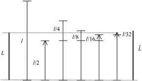
Figure 4.11: Principles of successive approximation
The process begins by choosing an initial yardstick length l. The value of l is set to half the largest coefficient in the image. If the coefficient is larger than the yardstick, it is represented with the yardstick value, otherwise its value is set to zero. After each pass the yardstick length is halved and the error magnitude, which is the difference between the original value of the coefficient and its reconstructed value, is compared with the new yardstick. The process is continued, such that the final error is acceptable. Hence, by increasing the number of passes the error in the representation of L by ![]() can be made arbitrarily small.
can be made arbitrarily small.
With regard to Figure 4.11, the quantised length L can be expressed as:
| (4.25) |
where only yardstick lengths smaller than the quantisation error are considered. Therefore, given an initial yardstick l, a length L can be represented as a string of 1 and 0 symbols. As each symbol 1 or 0 is added, the precision in the representation of L increases, and thus the distortion level decreases. This process is in fact equivalent to the binary representation of real numbers, called bit plane representation, where each number is represented by a string of 0s and 1s. By increasing the number of digits, the error in the representation can be made arbitrarily small.
Bit plane quantisation is another form of successive approximation that has been used in some standard codecs such as the JPEG2000 standard. Here, the wavelet coefficients are first represented by their maximum possible precision. This depends on the input pixel resolution (e.g. eight bits) and the dynamic range of the wavelet filter's coefficients. The symbols that represent the quantised coefficients are encoded one bit at a time, starting with the most significant bit (MSB) and preceding to the least significant bit (LSB). Thus for an M-bit plane quantisation with the finest quantiser step size of ∆, the yardstick is ∆2M-l. ∆ is called the basic quantiser step size.
4.4.2 Similarities among the bands
A two-stage wavelet transform (seven bands) of the flower garden image sequence with the position of the bands was shown in Figure 4.10. It can be seen that the vertical bands look like scaled versions of each other, as do the horizontal and diagonal bands. Of particular interest in these subimages is the fact that the nonsignificant coefficients from bands of the same orientation tend to be in the same corresponding locations. Also, the edges are approximately at the same corresponding positions. Considering that subimages of lower bands (higher stages of decomposition) have half the dimensions of their higher bands, then one can make a quad tree representation of the bands of the same orientation, as shown in Figure 4.12 for a ten-band (three-stage wavelet transform).
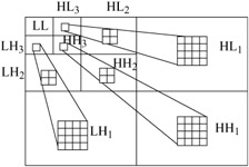
Figure 4.12: Quad tree representation of the bands of the same orientation
In this Figure a coefficient in the lowest vertical band, LH3, corresponds to four coefficients of its immediately higher band LH2, which relates to 16 coefficients in LH1. Thus, if a coefficient in LH3 is zero, it is likely that its children in the higher bands of LH2 and LH1 are zero. The same is true for the other horizontal and diagonal bands. This tree of zeros, called zero tree, is an efficient way of representing a large group of zeros of the wavelet coefficients. Here, the root of the zero tree is required to be identified and then the descendant children in the higher bands can be ignored.
EAN: 2147483647
Pages: 148