3.5 A generic interframe video codec
3.5 A generic interframe video codec
Figure 3.19 shows a generic interframe encoder which is used in all the standard video codecs, such as H.261, H.263, MPEG-1, MPEG-2 and MPEG-4 [20,16,21,22,17]. In the following sections each element of this codec is described in a general sense. The specific aspects of these codecs will be addressed in more detail in the relevant chapters.
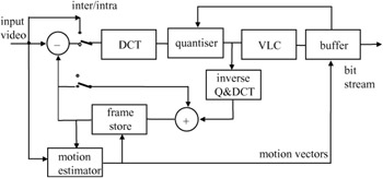
Figure 3.19: A generic interframe predictive coder
3.5.1 Interframe loop
In interframe predictive coding, the difference between pixels in the current frame and their prediction values from the previous frame is coded and transmitted. At the receiver, after decoding the error signal of each pixel, it is added to a similar prediction value to reconstruct the picture. The better the predictor, the smaller the error signal, and hence the transmission bit rate. If the scene is still, a good prediction for the current pixel is the same pixel in the previous frame. However, when there is motion, assuming that movement in the picture is only a shift of object position, then a pixel in the previous frame, displaced by a motion vector, is used.
3.5.2 Motion estimator
Assigning a motion vector to each pixel is very costly. Instead, a group of pixels are motion compensated, such that the motion vector overhead per pixel can be very small. In standard codecs a block of 16 x 16 pixels, known as a macroblock (MB) (to be differentiated from 8 × 8 DCT blocks), is motion estimated and compensated. It should be noted that motion estimation is only carried out on the luminance parts of the pictures. A scaled version of the same motion vector is used for compensation of chrominance blocks, depending on the picture format.
3.5.3 Inter/intra switch
Every MB is either interframe or intraframe coded, called inter/intra MBs. The decision on the type of MB depends on the coding technique, which will be explained in greater detail in the relevant chapters. For example, in JPEG, all MBs are intraframe coded, as JPEG is mainly used for coding of still pictures.
3.5.4 DCT
Every MB is divided into 8 × 8 luminance and chrominance pixel blocks. Each block is then transformed via the DCT. There are four luminance blocks in each MB, but the number of chrominance blocks depends on the colour resolutions (image format).
3.5.5 Quantiser
As mentioned in section 3.2, there are two types of quantiser. One with a dead zone for the AC coefficients and the DC coefficient of inter MB, the other without the dead zone is used for the DC coefficient of intra MB. The range of quantised coefficients can be from -2047 to +2047. With a dead zone quantiser, if the modulus (absolute value) of a coefficient is less than the quantiser step size q it is set to zero, otherwise it is quantised according to eqn 3.6, to generate quantiser indices.
3.5.6 Variable length coding
The quantiser indices are variable length coded, according to the type of VLC used. Motion vectors, as well as the address of coded macroblocks, are also VLC coded.
3.5.7 IQ and IDCT
To generate a prediction for interframe coding, the quantised DCT coefficients are first inverse quantised and inverse DCT coded. These are added to their previous picture values (after a frame delay by the frame store), to generate a replica of the decoded picture. The picture is then used as a prediction for coding of the next picture in the sequence.
3.5.8 Buffer
The bit rate generated by an interframe coder is variable. This is because the bit rate is primarily a function of picture activity (motion of objects and their details). Therefore, to transmit coded video into fixed rate channels (e.g. 2 Mbit/s links), the bit rate has to be regulated. Storing the coded data in a buffer and then emptying the buffer at the channel rate does this. However, if the picture activity is such that the buffer may overflow (violent motion) then a feedback from the buffer to the quantiser can regulate the bit rate. Here, as the buffer occupancy increases, the feedback forces the quantiser step size to be increased to reduce the bit rate. Similarly, if the picture activity is less (coding mainly slow motion parts of frames), then the quantiser step size is reduced to improve the picture quality.
3.5.9 Decoder
The compressed bit stream, after demultiplexing and variable length decoding (VLD), separates the motion vectors and the DCT coefficients. Motion vectors are used by motion compensation and the DCT coefficients after the inverse quatisation and inverse DCT are converted to error data. They are then added to the motion compensated previous frame, to reconstruct the decoded picture, as shown in Figure 3.20.
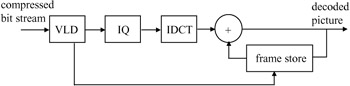
Figure 3.20: Block diagram of a decoder
EAN: 2147483647
Pages: 148