6.4 Graph-Based Clustering
6.4 Graph-Based Clustering
The coverage area of the network is to be divided into nonoverlapping clusters by means of the clustering algorithm. For clustering purposes, each node is assigned a unique ID number, and maintains a set of its single-hop neighbors. In one version of this clustering technique, called minimum ID, the node with the minimum ID among the neighbors is selected as the cluster head. The cluster head would have functionality similar to the AP mentioned previously.
A node turning on would listen to the beacons of the cluster head and configuration messages of the various nodes and join the cluster head with the minimum ID.
Each node transmits a clustering configuration message composed of the node ID and the thought-of cluster head ID to its neighbors. All neighboring nodes hear the message, adjust their conclusion in regard to cluster head election accordingly, but do not repeat this control message, but modify, and transmit a new configuration message. Each node in a cluster is at one hop away from the cluster head and, at most, two hops away from other nodes. A node, which is heard in two neighboring clusters, will belong to only one cluster.
A manager node also may exist in some systems, [11] where ad hoc network management is required, but this requirement is not a must for ID-based clustering, as shown in Figure 6.5.
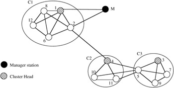
Figure 6.5: Clusters formed using graphical clustering.
It is possible also that one node (e.g., node 5 in Figure 6.5) can hear nodes from two different clusters, but will join only one. Clustering will take place according to cycles (timespan where topology is preserved, and through which a node keeps its thought-of cluster head ID). This cycle may vary from node to node. As an example, had node 1 been idle, node 2 would have been the cluster head of C1. But as soon as node 1 starts to transmit the clustering configuration messages, node 2 and other nodes in C1 will change their thought-of cluster head in the next clustering cycle.
If C1 and C2 clusters are formed in the same clustering cycle, then node 4 thinks of node 2 as the thought-of cluster head and thinks to join C1. However, after hearing from node 2 that node 1 is the thought-of cluster head, and because node 4 cannot hear node 1, node 4 will change its cluster configuration message so it becomes a cluster head of a new C2. Node 4 will not join C3 for a similar reason, i.e., it hears from node 5 that node 3 is the thought-of cluster head, but because it cannot hear node 3 directly, it will not accept node 3 as a cluster head and will start to form its own cluster.
Figure 6.5 assumes that clusters C2 and C3 were formed in the same clustering cycle; however, if C2 started to form before C3, then node 5 would have joined C2 instead (because nodes 3, 7, and 9 were idle, for example). Following the cluster formation and election of the cluster head, each node will keep the following database in regard to clustering:
-
Cluster list (all nodes in the cluster), neighbor list (all nodes one hop away)
-
A ping counter, which counts the time since the node last heard from the cluster head
As mentioned previously, when the cluster is formed each node is at one hop from the cluster head and two hops at most from other nodes in the cluster. As some of the nodes and cluster heads move in and out of the cluster, the cluster formation may be affected, as shown in Figure 6.6.
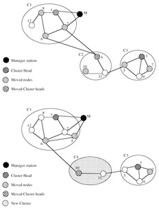
Figure 6.6: (a) Effect of node mobility on clusters. (Source— Chen, W., Jain, N., and Suresh, S., ANMP— Ad Hoc Network Management Protocol, IEEE J. Selected Areas Commun., 17 (8), 1506–1531, 1999.) (b) Effect of node mobility on clusters. (Source— Chen, W., Jain, N., and Suresh, S., ANMP— Ad Hoc Network Management Protocol, IEEE J. Selected Areas Commun., 17 (8), 1506–1531, 1999.)
A good clustering algorithm should yield cluster node selection, cluster head selection, and possibly gateway nodes that do not change much in the face of nodes mobility. As shown in Figure 6.6a, in C1 nodes 2, 6, and 8 moved but remain in C1; cluster head node 1 moved, is now at two hops from nodes 6 and 12, but still remains in C1. In C2, cluster head node 4 moved, is now at two hops from nodes 5 and 10, but still remains in C2. In C3, nodes 3, 5, and 7 moved and the result is similar. The conclusion from Figure 6.6a is that there is no need for reconfiguration of the clusters. However, in Figure 6.6b, node 4 (the cluster head of C2) moved too far from C2, and accordingly joins C1 (through node 2). On the other hand, nodes 10 and 11 find out that the cluster head has moved, and so form a new cluster C4, with node 10 becoming the cluster head. Because of node mobility as explained previously, some variations of the clustering rules [12] allow certain adaptability to mobility. One of those rules is the following:
If a node detects that it has lost its links to the nodes in its cluster, it either joins another cluster or forms another cluster by itself.
In this case, the node may join a cluster head, which is two hops away. For further adaptability to mobility, at regular intervals of time each node detects and reports to the cluster head one or more of the following events:
-
One neighbor in the same cluster moved out of the cluster.
-
One node moved into the cluster, and wishes to join the cluster.
-
One node became a neighbor and is a member of the cluster.
-
The node was at one hop from the cluster head, but now is at 2 hops or more.
-
The node was at two or more hops from the cluster head, but now is at one hop from the cluster head.
The cluster head will receive all those periodical reports from the nodes in its cluster, process them, and then broadcast a fresh list of cluster nodes to all nodes of the cluster.
The crucial function of the cluster head now becomes evident: if the cluster head moves, this leads to confusion among the member nodes. To protect against such an occurrence, a ping counter is incremented at each node at a regular interval of time. If the value of this counter exceeds a certain threshold, the cluster head broadcasts a ping message to all cluster nodes. On the other hand, if these nodes do not hear the ping message after their counters exceed the threshold, the nodes infer that the cluster head has been turned off or has moved out, in which case the voting process for establishing a new cluster head will commence again.
A number-crunching simulation involving 30 nodes [13] moving in a 1500 1500 unit area was conducted to test the resilience of the graph-based technique to mobility. The speed of each node varied in the range of 1 to 50 units per second, the transmission range was 450 units, and the nodes moved in random direction (uniformly distributed from 0 to 360 degrees). Figure 6.7 shows the number of messages exchanged to maintain the cluster in the face of mobility for different ping intervals, where no ping means infinite time steps, and 1 means one ping message every time interval. This number increases linearly with nodes' speeds.
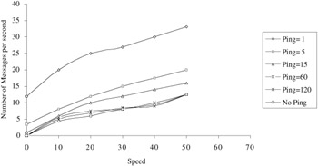
Figure 6.7: Control volume in graphical clustering.
Figure 6.8 shows the percentage of nodes unmanaged by cluster heads. Figure 6.8a outperforms those of Figure 6.8b due to the utilization of the available information from the 802.11 MAC layer.
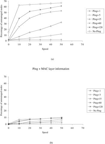
Figure 6.8: Percentage of nodes unmanaged by cluster heads. (Source— Chen, W., Jain, N., and Suresh, S., ANMP— Ad Hoc Network Management Protocol, IEEE J. Selected Areas Commun., 17 (8), 1506–1531, 1999.)
A similar graph-based clustering appears in Lin and Gerla, [14] where it is proved that the ID-based algorithm guarantees that each node joins only one cluster. Figures 6.9 and 6.10 show some of the simulation results from Lin and Gerla. [15] Figure 6.9 shows the average node connectivity of the algorithm versus the transmission range for different numbers of nodes N. Node connectivity refers to the number of nodes heard by a typical node. For a node to hear at least one neighbor, Figure 6.9 shows that the transmission range should be at most 40 for N = 20. Figure 6.10 shows that the average order of a typical repeater lies in the of range 2 to 3. This order is defined as the number of clusters this gateway node (repeater) can access.
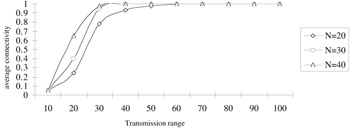
Figure 6.9: Connectivity property. (Source— Lin, C.R. and Gerla, M., Adaptive clustering for mobile wireless networks, IEEE J. Selected Areas Commun., 15 (7), 1265–1275, 1997.)
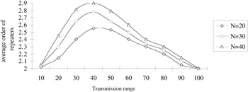
Figure 6.10: Average order of repeaters.
Maximum connectivity clustering [16] assigns the cluster head rule to the node that hears the maximum number of its one-hop nodes. This clustering technique is formulated as follows:
-
A node becomes a cluster head if it has the maximum number of "uncovered" nodes within one hop (hearing distance). A tie is broken based on minimum ID.
-
A node is said to be "uncovered" if it has not yet elected a cluster head, otherwise it becomes a "covered" node.
-
A node that has elected another node as cluster head will give up the cluster head rule if elected by other nodes.
Figure 6.11 shows a typical clustering configuration based on maximum connectivity clustering, where nodes 5, 7, and 8 are elected as cluster heads, while nodes 2, 3, 9, and 10 are gateway nodes.
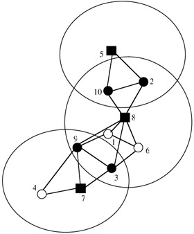
Figure 6.11: Example of cluster formation (highest connectivity). (Source— Gerla, M. and Tsai, J.T.C., Multiuser, mobile, multimedia radio network, Wireless Networks J., 255–265, 1995.)
Figure 6.12 compares the two strategies, i.e., minimum ID clustering and maximum connectivity clustering and shows the average number of clustering changes per clustering unit time (time tick) as a function of the transmission range. The minimum ID clustering yields less cluster changes than the other policy and thus is more stable in the face of nodes mobility. The reason is simple: if a node with highest connectivity moves away, many links are broken; with minimum ID clustering fewer links are broken, and hence the cluster may remain intact.
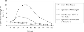
Figure 6.12: Comparisons of clustering (N = 30)— random movements. (Source— Gerla, M. and Tsai, J.T.C., Multiuser, mobile, multimedia radio network, Wireless Networks J., 255–265, 1995.)
[11]Chen, W., Jain, N., and Suresh, S., ANMP: Ad Hoc Network Management Protocol, IEEE J. Selected Areas Commun., 17 (8), 1506–1531, 1999.
[12]Chen, W., Jain, N., and Suresh, S., ANMP: Ad Hoc Network Management Protocol, IEEE J. Selected Areas Commun., 17 (8), 1506–1531, 1999.
[13]Chen, W., Jain, N., and Suresh, S., ANMP: Ad Hoc Network Management Protocol, IEEE J. Selected Areas Commun., 17 (8), 1506–1531, 1999.
[14]Lin, C.R. and Gerla, M., Adaptive clustering for mobile wireless networks, IEEE J. Selected Areas Commun., 15 (7), 1265–1275, 1997.
[15]Lin, C.R. and Gerla, M., Adaptive clustering for mobile wireless networks, IEEE J. Selected Areas Commun., 15 (7), 1265–1275, 1997.
[16]Gerla, M., Baltzer, J.C., and Tsai, J.T.C., Multiuser, mobile, multimedia radio network, Wireless Networks J., 255–265, 1995.
EAN: 2147483647
Pages: 239