6.3 Location-Based Clustering
6.3 Location-Based Clustering
The aforementioned clustering techniques apply to infrastructure networks where an AP is typically present. If all nodes (mobile stations) assume the same functionality and have similar processing capabilities, then the need arises for ad hoc clustering and routing techniques to enable roaming and forwarding of information and control packets to the appropriate destination. Although all nodes are similar in ad hoc networks, most routing and clustering protocols would assign certain functions to some nodes, i.e., cluster heads and gateways. Accurate position information could be available to the nodes as, for example, when GPS interfaces are available within the nodes, or when certain nodes transmit position aiding signals (pilots or beacons) so other nodes will know their location. Such position information could lead to facilitating the clustering and routing problems in ad hoc networks, [5] where a zone-based, two-level link state (called zone-based hierarchical LSR routing, ZHLS) is used for both clustering and routing.
The network area is divided into nonoverlapping numbered zones, and a typical node address consists of node ID and zone ID (by reading from a memory table, the GPS coordinates of the node translate into its current zone ID). Although the emphasis here is on clustering and not routing, [6] the two functions are interleaved in most ad hoc networks.
The hierarchical address corresponds to the node-based and zone-based topologies, as shown in Figure 6.2. The zone size depends on the nodes' power, geography, application, etc.
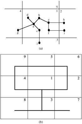
Figure 6.2: (a) Node-based topology. (b) Zone-based topology.
The clustering and routing procedures consist of two phases: intrazone and interzone. In the first phase, neighboring nodes exchange their link state packets (LSP), each consisting of the node ID and zone ID. As shown in Figure 6.3, node a sends a link request, receives a link response from neighbors (at one-hop hearing distance), formulates its LSP (Table 6.1), and broadcasts it to all neighbors.
| Source | Node LSP |
|---|---|
| a | b, c, d, 4 |
| b | a, e |
| c | a, 3 |
| d | a |
| e | b, f, m, 2 |
| f | e, 2 |
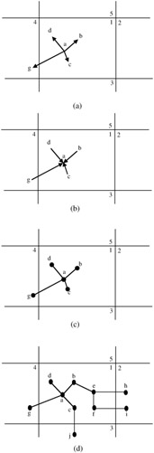
Figure 6.3: Intrazone clustering procedure. (a) Node a broadcasts a link request to its neighbors. (b) Node a receives link responses from its neighbors. (c) Node a generates its own node LSP and broadcasts it throughout the zone. (d) All nodes perform the previous steps asynchronously. (Source— Jao-Ng, M. and Lu, I.-T., A peer to peer zone-based two-level link state routing for ad hoc networks, IEEE J. Selected Areas Commun., 17 (8), 1415–1425, 1999.)
All nodes perform the same steps asynchronously. In Table 6.1, which shows all LSPs of zone 1, each table entry corresponds to all immediate neighbors of each node as well as the neighboring zone of that node.
As an example, node a has b, c, and d as immediate neighbors and can reach the neighboring zone 4 through node g, while node d has only a as a neighbor and cannot reach any neighboring zones. From Table 6.1, node a derives Table 6.2, which shows the intrazone (same zone) routing table of node a. As an example, for node a to reach node c, it will go directly to node c (same zone). For node a to contact any node in zone 2, it will go through node b [as in Figure 6.3d, the border node h in zone 2 hears node e, which in turn hears node b].
| Destination | Next Node |
|---|---|
| b | b |
| c | c |
| d | d |
| e | b |
| f | b |
| 2 | b |
| 3 | c |
| 4 | g |
At the end of the first phase (intrazone) and following the exchange of all LSPs by all nodes of each zone, each node would then have the same table of zone LSPs.
In the second phase (interzone), the gateway nodes [those hearing messages from different zones such as nodes e, a, f, and c of Figure 6.3d] will propagate the zone LSPs through the network, as illustrated in Figure 6.4. This will enable each node to store a zone LSP similar to the one in Table 6.3. Taking the fourth entry of this table means the neighboring zones of 4 are 1, 9. Figure 6.4b shows the spanning tree or virtual links between the zones in this network.
| Source | Node LSP |
|---|---|
| 1 | 2, 3, 4 |
| 2 | 1, 6 |
| 3 | 1, 7, 8 |
| 4 | 1, 9 |
| 5 | 6, 9 |
| 6 | 2, 5 |
| 7 | 3 |
| 8 | 3 |
| 9 | 4, 5 |
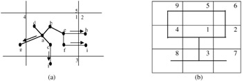
Figure 6.4: Interzone clustering procedure. (a) Gateway nodes broadcast zone LSPs throughout the network. (b) Virtual links between adjacent zones are established. (Source— Jao-Ng, M. and Lu, I.-T., A peer to peer zone-based two-level link state routing for ad hoc networks, IEEE J. Selected Areas Commun., 17 (8), 1415–1425, 1999.)
Because each node receives all zone LSPs (Table 6.3), shortest-path algorithms are used at each node to find the best route to each zone, as shown in Table 6.4.
| Destination Zone | Next Zone | Next Node |
|---|---|---|
| 2 | 2 | b |
| 3 | 3 | c |
| 4 | 4 | g |
| 5 | 4 | g |
| 6 | 2 | b |
| 7 | 3 | c |
| 8 | 3 | c |
| 9 | 4 | g |
Routing of data messages is now proactive if the destination lies within the same zone as the source, according to Table 6.2, and reactive if the destination is not within the same zone. In the later case, a route search is conducted and the facilities of the zone LSPs of Table 6.3 and the various nodes interzone routing (Table 6.4) are used to find an end-to-end route. See Elhakeem [7] and Jao-Ng and Lu [8] for further routing details.
Needless to say, exchange of node LSPs and zone LSPs among nodes will cause some flooding, which can be minimized if repeated LSP messages are not transmitted again by any node. To have some idea about savings in the cost of control messages, one finds that in a flat topology, the number of control messages exchanged per clustering cycle is defined as:
| (6.1) |
where U is the total number of nodes, because each node transmits one clustering message to every other node. A flat topology assumes that all nodes are considered to be in one large zone.
In the location-based technique described previously, each node transmits one node LSP message to every other node in its zone, the average number of these nodes per zone is U/Z, where Z is the number of zones and the number of these messages become Z(U/Z)2 = U2/Z. This adds to the total number of zone LSP messages, UZ, to give the total number of control messages per clustering cycle in ZHLS, i.e.,
| (6.2) |
Clearly, Cg is less than Cf.
Although the selection of zone size is restricted by the radio powers of the nodes, channel conditions, and network deployment among other factors, it is possible to find the optimal number zones by differentiating Cg and equating to zero, thus obtaining
| (6.3) |
and optimal Cg = 2N3/2 control messages. In the face of nodes' mobilities, and if the ratios of nodes generating node and zone LSPs due to mobility are pa and Pb, respectively, then the control overhead per cycle of ZHLS due to mobility becomes
| (6.4) |
while for flat topology
| (6.5) |
Because zone topology changes are less frequent than node-level changes, pa is greater than pb, and hence
| (6.6) |
Jao-Ng and Lu [9] present simulation results that display the superiority of zone clustering using GPS; also, Chen and coworkers [10] report a similar location-based technique, called geographical-based routing and clustering technique, which emphasizes radio range considerations in the process of zone formations. These clustering techniques are typically implemented within the application layers above the wireless IEEE 802.11 MAC layer. We notice that only gateways (not cluster heads or APs) are defined here, and that both gateways and ordinary nodes cooperate to route nodes packets from source to destination based on the routing tables mentioned previously.
[5]Jao-Ng, M. and Lu, I.-T., A peer to peer zone-based two-level link state routing for ad hoc networks, IEEE J. Selected Areas Commun., 17 (8), 1415–1425, 1999.
[6]Elhakeem, A.K., Ad-hoc routing techniques for wireless LANs, in The Communications Handbook, 2nd ed., Gibson, J.D., Ed., CRC Press, Boca Raton, FL, 2002, 92-1.
[7]Elhakeem, A.K., Ad-hoc routing techniques for wireless LANs, in The Communications Handbook, 2nd ed., Gibson, J.D., Ed., CRC Press, Boca Raton, FL, 2002, 92-1.
[8]Jao-Ng, M. and Lu, I.-T., A peer to peer zone-based two-level link state routing for ad hoc networks, IEEE J. Selected Areas Commun., 17 (8), 1415–1425, 1999.
[9]Jao-Ng, M. and Lu, I.-T., A peer to peer zone-based two-level link state routing for ad hoc networks, IEEE J. Selected Areas Commun., 17 (8), 1415–1425, 1999.
[10]Chen, W., Jain, N., and Suresh, S., ANMP: Ad Hoc Network Management Protocol, IEEE J. Selected Areas Commun., 17 (8), 1506–1531, 1999.
EAN: 2147483647
Pages: 239
- Chapter VII Objective and Perceived Complexity and Their Impacts on Internet Communication
- Chapter XI User Satisfaction with Web Portals: An Empirical Study
- Chapter XV Customer Trust in Online Commerce
- Chapter XVI Turning Web Surfers into Loyal Customers: Cognitive Lock-In Through Interface Design and Web Site Usability
- Chapter XVII Internet Markets and E-Loyalty