Chapter 10: Hardware Testbeds, Instrumentation, Measurement, Data Extraction, and Analysis
|
| < Free Open Study > |
|
Overview
In the previous chapters, we covered modeling from several perspectives, ranging from simulation to queuing models to Petri nets and to operational analysis. For those perspectives, only limited amounts of data are actually measured on an actual system. Often, the simplifying assumptions that are made so that model results are calculable enable us to obtain only an approximate analysis of the system's behavior. Also, the load conditions that are presented to an analytical or simulation model often are not tested in a real-world situation. These factors have two ramifications. The first is that more detailed analysis is difficult because of the lack of adequate real-world data. The second is that, even with a detailed model, validation of the model and its results must be weak at best. The latter statement is especially true for general-purpose simulation models such as those discussed throughout this book. Before a simulation can be used to predict the performance of any system, the results of its execution must be compared against a known baseline, and the simulation must be adjusted accordingly. One method of achieving this is through the instrumentation and collection of performance data on an actual system. The results of these measurements are compared with the predicted results from a simulation model of the same system. When the results agree to within some predetermined tolerance, the model is considered validated.
This chapter discusses the use of prototype hardware testbeds as a tool for ascertaining actual measures for some of the performance quantities of interest, for performing controlled experiments to determine the operational characteristics of different parts of a network, and for the validation of software simulation models. In particular, we will describe the implementation of a hardware testbed, define the measurable quantities that we are interested in, derive operational relationships for nonmeasured quantities, and give some results.
The construction of a special-purpose testbed can be costly if done solely for the purpose of estimating the final system performance. Often, however, a proof of concept prototype is constructed to test and validate design assumptions, to gain experience with the system, and to provide a vehicle for advanced development. Given that a prototype system often exists, it is advantageous to also consider instrumentation and test provisions in the prototype design. When performed within the scope of the prototyping effort, the relative cost of special performance measurement facilities becomes more acceptable. Some important facilities, which we will describe for a specific example later in this chapter, could include a system-wide time base for obtaining synchronous measurements, time-tagging hardware or software for timestamping events, counters for recording the number of occurrences of important events, and scenario drivers that can inject a known load into the system being modeled. Of course, it is desirable to make these facilities as unintrusive as possible so that their use does not interfere with the normal operation of the network under question. In some cases, portions of the final system software configuration may be substituted by special-purpose measurement facilities. The remainder of this chapter will discuss a prototype network configuration and will illustrate the techniques employed to measure its performance characteristics.
The network that we will be discussing is situated in a prototype testbed that is instrumented for data collection and can generate network traffic. Each testbed node contains a host controller that can emulate a known traffic load or generate any specified pattern of message traffic. Experiments can be repeated so that different measurements can be taken or so that a specific communication-related parameter can be varied. Thus, the prototype system's loading and recording mechanisms can be controlled in order to observe different network performance phenomena.
In constructing a prototype testbed such as the one discussed here, it is desirable to keep hardware development costs at a minimum, to provide a flexible system so that changes in network design can be accommodated, and to provide the general-purpose driver capabilities discussed previously. One method of keeping hardware development costs down is to use off-the-shelf hardware components as much as possible. All node components that are not network specific can be implemented using standard board or system-level products. For example, the host processor for a node could be implemented with a single board computer or even with a personal computer.
Flexibility in the design of the network-specific components is essential for minimizing the impact of the inevitable design changes that occur during the early network design and prototyping phase. One useful method for achieving a flexible prototype design is to reduce the speed of operation of the network. This allows some functions of the network to be implemented with more general-purpose components, such as a programmable microcontroller or state machine. After the prototype design has been analyzed and a near-final configuration decided upon, these functions can be transitioned into higher-speed implementations. The assumption here is that a uniform scaling of the speed of operation across all network-sensitive components will yield results that can be scaled back up to reflect the actual system's performance. This may not hold true in the strictest sense, such as where hardware characteristics change at higher speeds, but it will generally hold if the functionality of the network as a whole does not change.
In order to provide general-purpose network driver and data collection capabilities, it is almost always necessary to have a detached host, whose only function is to generate network traffic and collect results. Also, it may be necessary to design in additional resources, whose only functions are to assist in traffic generation of data collection. It is important to adhere as much as possible to a layered network standard such as the International Organization for Standardization's model for Open Systems Interconnection reference model (ISO's OSI model). By doing this, changes can be more or less localized to the level that is most affected, whereas the other levels can maintain their functionality. Thus, the same standards that provide a degree of interoperability among networks of different types also provide us with a useful template for building a flexible prototype system.
The hardware testbed used here, for example, consists of several network nodes connected with a token bus LAN. Each node contains two single-board computers: one that implements the simulated host functions (the host) and provides for network loading and data collection and one that provides high-level control functions for the network hardware (the input/ output processor, or IOP). Additionally, each node contains a network adapter, whose function is to implement the network protocol.
In this particular case, the network testbed models a general-purpose serial communication network. With a stable host and IOP design, a number of different network types can be implemented by using different network adapters and front-end hardware. The network that we will examine uses a token access protocol. In this protocol, the node that holds the token has the option to transmit data, if there is message traffic queued for transmission by the host processor. If the node does have a message to send, it broadcasts the message over the communication bus. All other nodes listen for their identifying address in the message header and accept the message if it is destined for them. After the transmission of a message has been completed, or if there is no message to send, the token is passed to the next node on the network in a round-robin manner. The next node may or may not be physically adjacent to the current node. The overall structure of the network testbed is shown in Figure 10.1.
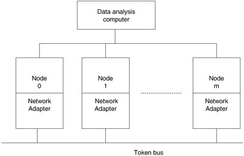
Figure 10.1: General testbed configuration.
A number of nodes, each with a network adapter, are attached to a linear token bus and also to a data analysis computer. During a test run, the network bus is used to transfer the simulated load. At the completion of the test, each node transmits its collected data to the data analysis computer for synthesis and analysis. Each node within the network testbed has an architecture, as shown in Figure 10.2.
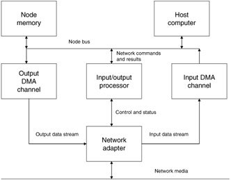
Figure 10.2: Testbed node architecture.
The host computer serves two functions in this architecture. The first is to implement part of the layered protocol and to provide a simulated message load to it. The second is to collect the necessary performance data for subsequent analysis. Figure 10.3 shows the general structure of the host software that implements these functions.
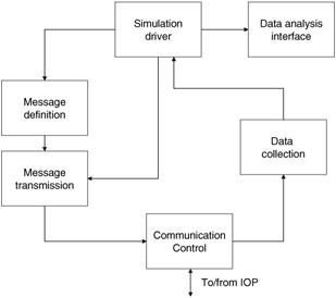
Figure 10.3: Host software architecture.
The IOP controls the flow of message traffic onto and off of the network through the network adapter. It also controls the DMA channels, provides a standard interface to the host computer, and collects network-specific performance statistics. Figure 10.4 shows the IOP's functional architecture.
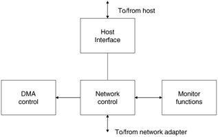
Figure 10.4: IOP functional architecture.
As mentioned earlier, it is advantageous to have the testbed components conform to a layered protocol standard. The testbed under discussion here implements levels 1 through 4, and part of level 5, of the OSI model for layered protocols. Figure 10.5 shows how the various components map to the standard. In the layered model shown in Figure 10.5, the physical level implements the electrical and physical functions that are required to link the nodes. The data link layer provides the mechanisms necessary to reliably transmit data over the physical link. Level 3, the network level, controls the switching of data through the network. In networks with multiple transmission paths, the level 3 function controls over which links a message will be transferred. At the transport level, an error-free communication facility between nodes is provided. Session control involves the initiation, maintenance, and termination of a communication session between processes. Level 6 provides any data translation, compaction, or encoding/decoding services that may be required by the application. At the top resides the application, which is any process that uses the communication facilities.
| ISO/OSI Level | Test-bed |
|---|---|
| Level 7: application | simulation driver |
| Level 6: transformation/presentation | not implemented |
| Level 5: session | partially implemented |
| Level 4: transport | IOP |
| Level 3: network | |
| Level 2: data link | network adapter |
| Level 1: physical |
Figure 10.5: Testbed/ISO correspondence.
For the example network, levels 1 and 2 provide physical connection via coaxial cables, the serialization and packing of data, and the synchronization and detection of data onto and off of the network. Since the network discussed here is a global bus, there is no need for the switching functions of level 3. In cases where this is a factor, however, the function would be implemented in the IOP. Transport control is best implemented in the IOP, because it relieves the host of performing error detection and retransmission and of managing individual message packets. Part of level 5 is implemented in the host so that messages can be assembled and queued for transmission to other nodes. Mechanisms for establishing interprocess connections are not implemented.
The network that we will study as an example requires the acknowledgment of each message packet from the receiver. A missing or bad acknowledgment results in the retransmission of the packet in error. Messages are addressed to logical process identifiers, which are mapped to each node upon initialization.
In the testbed model, a sequence of messages is treated as a series of time-ordered events. The event times are generated in the host according to a probability distribution that is representative of the desired loading characteristics. The time of message generation is recorded and collected for postrun analysis. As a message is transferred through the protocol layers and across the network, it is time-tagged, again for later analysis. In the following section, we will illustrate the use of these time tags and other collected data from a run, derive the performance evaluation parameters of interest, and show some experimental results that exemplify the techniques.
|
| < Free Open Study > |
|
EAN: 2147483647
Pages: 136
- The Second Wave ERP Market: An Australian Viewpoint
- Enterprise Application Integration: New Solutions for a Solved Problem or a Challenging Research Field?
- Context Management of ERP Processes in Virtual Communities
- Distributed Data Warehouse for Geo-spatial Services
- Development of Interactive Web Sites to Enhance Police/Community Relations