Load Balancing, Load Sharing, and High Availability
| Load balancing between IPSec VPN tunnels provides some of the benefits of High Availability but, in general, meets a different set of design objectives than does HA. When discussing HA designs, we have typically included designs in which redundancy is built into the IPSec system. Specifically, these are designs that have IPSec VPN tunnels which are used strictly for backing up encrypted communications when the primary IPSec VPN tunnel is downonly one tunnel, main or standby, is used at a time. When traffic is load balanced between multiple IPSec VPN tunnels, the traffic flows are divided and shared across the IPSec VPN tunnels. Unlike the redundancy options discussed up to this point, a load-balancing design uses multiple IPSec VPN tunnels simultaneously and therefore does not take a main/backup approach to IPSec VPN design. That said, load-balanced designs provide some degree of HA, since when any one of the IPSec VPN tunnels supporting the load-balanced design fails, the remaining operational IPSec VPN tunnels can assume the extra load that was originally forwarded through the failed IPSec VPN tunnel. In this section, we will explore several methods for building load-balanced IPSec VPN designs. Load-Sharing with Peer StatementsIPSec VPNs can use the underlying routing protocol to load balance encrypted traffic across multiple paths. Although the effectiveness of load-balancing IPSec VPN tunnels using routing protocol depends somewhat on the capabilities of the routing protocol itself (such as equal-cost load-balancing capabilities within OSPF), a load-balanced solution also requires the appropriate configuration of crypto ACLs, crypto maps, and crypto peers. Figure 5-13 illustrates a scenario in which the crypto ACLs are configured to load balance traffic between two IPSec VPN tunnels between IPSec_A and IPSec_B. Figure 5-13. Multiple Peer Statements and Load Balancing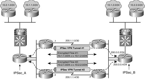 Routing-protocol traffic between the two IPSec VPN endpoints, IPSec_A and IPSec_B, is exchanged in cleartext, allowing the IPSec tunnels to be built, as in Figure 5-13. RRI is used to preserve routing continuity between the two routed domains on opposite ends of the IPSec tunnel between IPSec_A and IPSec_B. The traffic flows in Figure 5-13 are forced over the two IPSec tunnels in a load-shared format by configuring the crypto ACLs to forward traffic over the corresponding tunnel to the appropriate peer IP addresstraffic from 10.1.1.0/24 to 10.1.2.0/24 takes Path #1, while traffic from 10.2.1.0/24 to 10.2.2.0/24 takes Path #2. Examples of proper and improper usage of load balancing with alternate peering statements are illustrated in Examples 5-1 and 5-2, respectively. Example 5-1. Using Multiple Peering Statements for Load Balancing and Redundancy
Note that in Example 5-1, traffic is manually shared between two different tunnel termination endpoints, 200.0.0.2 and 200.0.0.4, by splitting the traffic flows out into separate crypto ACLs, 101 and 102. Let us now look at a configuration example where multiple peers are used, but only for pure redundancy and no load balancing. Using the configuration listed in Example 5-2, IPSec_A uses 200.0.0.2 as the destination tunnel termination address for the encrypted traffic flow specified in crypto ACL 101. If 200.0.0.2 is unavailable, the crypto engine will use 200.0.0.4 for IPSec peering for traffic matching ACL 101. Unlike Example 5-1, ACL 101 is configured to match all traffic flows. This results only in IPSec tunnel termination point redundancyno load sharing is achieved.. Example 5-2. Using Multiple Peering Statements for Redundancy Only
RoutingRemember that one key benefit of Layer 3 (L3) encryption technologies, like IPSec over Layer 2 (L2) encryption technologies, is that traffic flows can be kept confidential and secure over multiple L2 domains. It is therefore important that the underlying routing protocol between IPSec tunnel termination endpoints be configured to evenly distribute IPSec traffic across multiple available L3 paths en route to the appropriate target tunnel termination point. Figure 5-14 shows some examples of appropriate and inappropriate IPSec traffic distribution across multiple routed paths between the tunnel termination endpoints. Figure 5-14. Intermediate RP Impact on IPSec Traffic Flow Distribution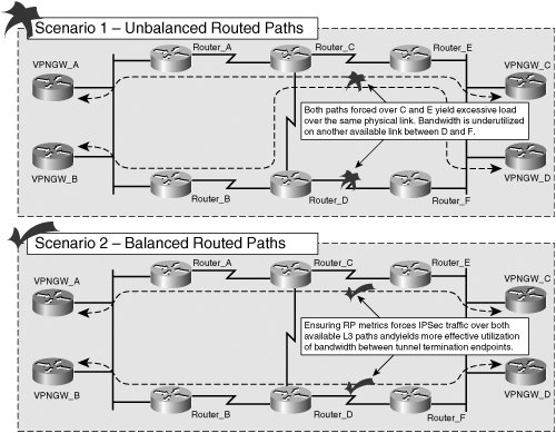 Domain Name System (DNS)IPSec clients can be configured to use DNS to resolve the IP address of their IPSec peer. This allows designers to use DNS server load balancing to distribute the number of IPSec sessions across multiple IPSec VPN concentrators. In this type of design, the DNS server would resolve the same hostname to multiple addresses. When it receives a query from one of the IPSec clients to resolve the concentrator's hostname to a given IP address to be used for Phase 1 and 2 negotiations, the DNS server would return the first IP address associated with the concentrator's hostname. The DNS server would then continue to map subsequent resolutions to the other addresses mapped with the concentrator's hostname, yielding a round-robin distribution of inbound IPSec sessions from the IPSec VPN clients across the various IPSec VPN concentrators. Figure 5-15 illustrates the mechanics of a DNS-based, load-balanced IPSec RAVPN implementation. Figure 5-15. DNS-Based Load Balancing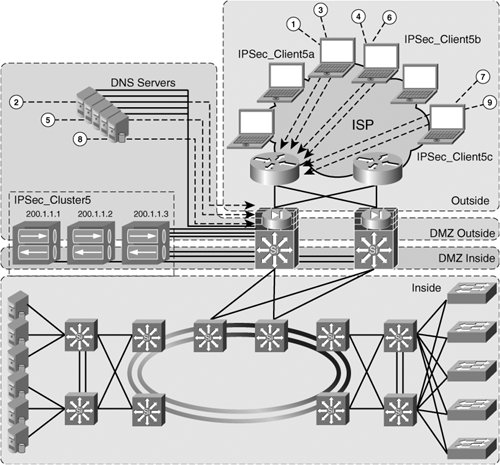 Note The Cisco IPSec VPN 3000 series of VPN concentrators support load balancing through concentrator clustering. We will discuss this method of load balancing later in this section. However, when using concentrators where clustering is not supported, DNS-based load-balancing solutions present an effective alternative to load-balanced RAVPN solutions. The following sequence of operations corresponds to the order of operations illustrated in Figure 5-15, outlining the DNS-based load balancing of IPSec tunnels from VPN clients to the IPSec VPN cluster:
Caution The example above illustrates a basic round-robin distribution of DNS resolutions as clients request the IP address corresponding to the name of their VPN Concentrator. Take care when configuring your DNS server to ensure that the DNS name resolutions are being returned in the appropriate order with which you would like the sessions to be load balanced across your VPN concentrators. Subsequent clients follow the same round-robin approach since the DNS server returns the three IP addresses in a round-robin fashion each time a name resolution request for IPSec_Cluster5 from the clients. This results in an even distribution of IPSec client sessions within the concentrator cluster. Cisco VPN3000 Concentrator ClusteringVPN concentrator clustering enables network administrators to effectively distribute the load of IPSec VPN tunnels from remote IPSec VPN clients. Recall that DNS-based load balancing maps multiple VPN concentrator IP addresses to a common DNS name which all clients use to establish their IPSec VPN tunnels. DNS-based load balancing of IPSec sessions therefore provides a round-robin distribution of inbound IPSec VPN sessions on the concentrator IP addresses that share the same hostname. Note VPN3000 Clustering is a Cisco proprietary function. For environments that use IPSec VPN concentrators from other manufactures, another alternative such as DNS-based load balancing should be considered. One major limitation of this type of deployment is that the DNS server that is doing the load balancing has no awareness of the current load on the concentrator to which it is effectively assigning the next inbound IPSec VPN session. This is not the case in a clustered deployment of IPSec VPN3000 concentrators. VPN3000 concentrators can be configured to intelligently direct inbound IPSec VPN connections from IPSec clients to the concentrator with the lowest load. This is accomplished through Virtual Cluster Agent (VCA) protocol communications between the VPN3000 concentrators in the cluster. Each concentrator in the VPN3000 cluster running the Virtual Cluster Agent protocol is considered to be a Virtual Cluster Agent (VCA). Within the cluster, there is a master VCA and secondary VCAs. The master VCA monitors the load of the secondary VCAs using the VCA protocol to determine which concentrator has the lowest load and, subsequently, which concentrator to redirect the next IPSec VPN tunnel initiation request to. We will discuss the step-by-step process of inbound IPSec VPN tunnel termination from remote IPSec VPN clients on a VPN3000 concentrator cluster, but first let's discuss the VCA configuration tasks that must be accomplished on the VPN3000 to achieve IPSec VPN load balancing within the cluster:
Note Remote Access High Availability is discussed more comprehensively in Chapter 9, "RAVPN High Availability," including the detailed configuration of VCA clustering on VPN3000 series IPSec VPN concentrators and ASA5500 series VPN appliances. Figure 5-16 depicts a scenario in which inbound IPSec VPN sessions are load-balanced between a cluster of Cisco VPN3000 concentrators. Figure 5-16. IPSec Session Load Balancing Using VPN3000 Concentrator Clustering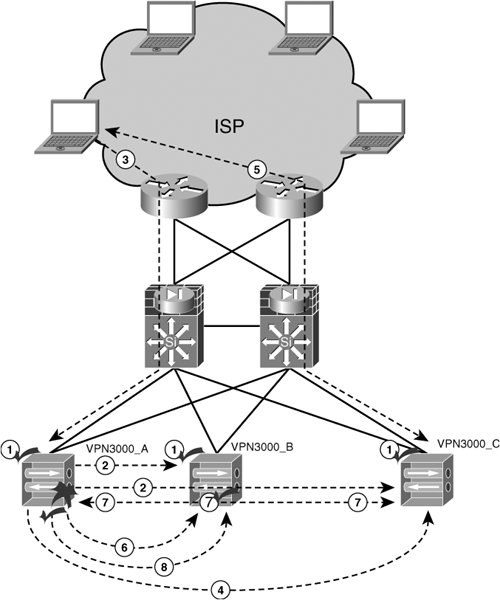 Next, we will explore the steps taken when a new remote IPSec VPN client initiates an IPSec tunnel to the concentrator cluster. The following is an explanation of the numbered steps in Figure 5-16:
It is important to observe the behavior of the cluster upon failure of one of the concentrators. Were this to occur, a DNS-based round-robin session load balancing alternative would continue to evenly load balance sessions across the concentrators in the cluster, unaware that VPN3000_A is vastly underutilized after it recovers in Step 8, described above. Using the VCA protocol, VPN3000 concentrators can make this distinction and therefore have enough load-balancing intelligence to assign IPSec client sessions to the underutilized concentrator until its load is roughly equal to that of the other concentrators in the cluster. IPSec Session Load-Balancing Using External Load BalancersUsing an external load balancer to distribute IPSec VPN sessions to their corresponding concentrator could prove to be a useful design choice when VPN clustering is not an option. As VPN Concentrator clustering is only supported on VPN3000 Series Concentrators, this design scenario could present itself when another brand of concentrator is selected. Figure 5-17 shows a sample topology that uses a Content Switch Module (CSM)in the 6509 switch facing the VPN concentrators. Figure 5-17. Load Balancing IPSec VPN Sessions with External Load Balancers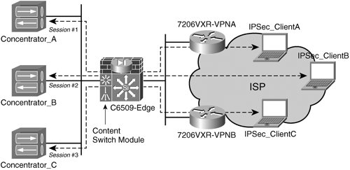 The content switch module in Figure 5-17 is distributing IPSec VPN sessions to the concentrators behind it in a round-robin fashion. Unlike a cluster of VPN3000 concentrators running the VCA protocol, the CSM will not normally query the concentrators behind it for detailed session-load information unless a script is executed on the concentrator instructing it to do so. Instead, the CSM will only query the concentrator for its operational state using ICMP probes. The 6500 CSM does support scripting languages, such as TCL, which could be used to instruct the CSM to query (for example, with SNMP) the concentrators for information on their current session load, which in turn could be used to execute the load-balancing decision on the next inbound IPSec VPN session. Warning Although the CSM does allow administrators to write scripts that could be used for inbound IPSec session load balancing, support for this solution is severely limited. Additionally, the configuration, maintenance, and operation of this solution are all far more difficult than that of virtual clustering with VPN3000 series concentrators and ASA5500 VPN appliances. Tip The CSM supports scripting languages, such as TCL, that could be used to configure the CSM to query (for example, with SNMP) the concentrators for their tunnel load. The CSM could then use that information to load-balance the inbound IPSec VPN tunnels across the VPN concentrators behind the CSM. Although this presents a viable alternative to session load balancing, using VCA clustering on the VPN3000s is the best supported solution for dynamic session load balancing on VPN3000 IPSec VPN concentrators and ASA5500 VPN appliances. The CSM can, however, direct inbound IPSec sessions to the concentrator with the lowest session load. The CSM accomplishes this by keeping a state table of the connections that pass through it. This allows the CSM to quickly identify which concentrators have been assigned the most sessions and which have been assigned the least, enabling the CSM to rapidly redirect inbound IPSec VPN tunnel initiation requests to the appropriate concentrators. |
EAN: 2147483647
Pages: 113