Legacy DAS Interconnects
| Two legacy direct attached storage (DAS) interconnects are commonly used in SAN and NAS products:
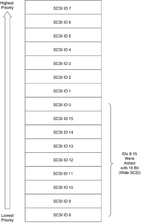
The parallel SCSI bus, which began its history as part of the same technology as SCSI logic and protocols, is the leading interconnect for server systems and UNIX desktops. It has excellent performance characteristics and a great deal of versatility to support a wide range of functions and devices. Parallel SCSI is relatively expensive compared to ATA. ATA was invented as an inexpensive disk interconnect for PC desktop computers. It is much more limited than parallel SCSI in both expandability and device support, but the cost of ATA technology is lower than any other storage interconnect technology. Parallel SCSI and ATA are examined in the sections that follow. The Parallel SCSI Bus: the Legacy Server Storage InterconnectThe parallel SCSI DAS bus is the legacy storage interconnect technology for open-systems servers. There have been many different versions of parallel SCSI over the years. The current technology is low-voltage differential (LVD) SCSI. NOTE Most of the time the word SCSI is used to refer to parallel SCSI. In fact, the word parallel is not often used with SCSI in product descriptions or most conversations. So why use it here? For clarity, mostly, but also to help drive home the point that there is a huge difference between the logical stuff of storing and the physical stuff of connecting that coexists in the wide world of SCSI technology. Parallel SCSI was invented as a single-controller interconnect technology. More than just a storage bus, parallel SCSI is used for several different types of devices, including scanners and printers. Its versatility helped establish it as an all-purpose interconnect, although today it is thought of primarily as a storage interconnect. While parallel SCSI has excellent performance characteristics, it has many shortcomings as a way to connect enterprise storage. The cable distances are very short compared to SAN network distances, and the number of connected target addresses limits the scalability and therefore the storage capacity of the SCSI bus. In addition, parallel SCSI was never designed for dual-controller, high-availability environments, although it could be accomplished through specially designed controllers and subsystems. The typical parallel SCSI implementation involves a single server with one or more HBAs providing connections to storage. In this configuration, the server is a potential bottleneck and a single point of failure. Parallel SCSI Bus ConnectionsParallel SCSI buses are formed by the collection of cables and devices that are connected. There are different physical approaches to making these connections, but the fundamental idea is that every device on the parallel SCSI bus connects to the same set of wires. Each device has a unique address that is independent of the physical location on the bus. In that sense, the parallel SCSI bus is similar to other familiar buses, such as system buses. Configuration changes to parallel SCSI buses require the bus to be powered down, which for many systems means that the system itself must also be powered down. This obviously limits its use for high-availability environments where data access is expected on a 24/7/365 basis. Maintenance for high-availability systems using parallel SCSI storage normally has to be done during weekend hours, when data access needs are reduced. Unplanned maintenance events, such as unexpectedly running out of disk space, can create an administrative emergency for data center managers. SCSI buses have limited lengths that need to be carefully considered. LVD SCSI has a maximum bus length of 12 meters, encompassing both internal and external cables. Most previous versions of the SCSI interconnect had shorter connection lengths, some as small as 1.5 meters. The exception, differential SCSI, allowed bus lengths up to 25 meters. Historically, the variations in the different versions of parallel SCSI were a source of frustration and unnecessary costs. NOTE For a technology that was supposed to be a standard, parallel SCSI over the years hardly resembled one, with a constant parade of connecting interfaces that always seemed to be changing. Normally standards are supposed to result in lower commodity pricing in things like cabling, but in the case of parallel SCSI, the cables and connectors are comparatively very expensive. Even today, with a relative stabilizing in the LVD bus, retail prices for cables range from $20 to $50, depending on the number of connectors on them. The fact is, the cost of a cable can be equal to or even greater than the cost of a device. Similar cables for ATA drives have fewer connectors but have retail costs between $3 and $15. The cost of cabling was only part of the frustration with parallel SCSI. Adapters to connect devices with older interfaces to newer buses typically cost between $15 and $25. The cost of terminating resistors for the bus is also high. A bus terminator for differential SCSI costs $50 or more. To make matters worse, often the connector would not specify whether it was differential or single-ended SCSI, even though the parts were not interchangeable. So why did people use parallel SCSI if it was such a pain in the backside? Because it was the fastest interconnect available. In many cases it was the only thing fast enough for high-performance applications. The need for speed was at the heart of the cabling/configuration problems. SCSI had to evolve in response to faster and faster system requirements. In the same time that system CPUs went from 25 MHz to more than 2 GHz, the SCSI interconnect has gone from 10 MBps to 320 MBps. Even though the performance improvement of parallel SCSI does not match the performance of CPU processors, it has not become a bottleneck. That honor still belongs to electromechanical devices such as disk drives. Parallel SCSI Addresses, Arbitration, and PriorityEvery controller and device on a parallel SCSI bus has a unique address. Today's LVD parallel SCSI bus has a maximum of 16 total addresses, including an address for the initiator. Addresses are assigned several different ways, depending on the product, including device management software, device driver settings, switches, and jumpers. If two entities are assigned the same address, the bus won't operate. Initiators and targets gain access to the parallel SCSI bus through a process called SCSI arbitration. If only one entity arbitrates for control of the bus, it gets to control the bus for a short period of time. If more than one entity arbitrates, the entity with the highest priority gets to control the bus. The priority of an entity on the parallel SCSI bus is determined by its address. For historical compatibility reasons, the highest-priority address on an LVD SCSI bus is 7. This is usually assigned to the HBA. The next-highest-priority address is 6, followed by 5, and then 4, and so on until address 0. Then the addresses and priorities resume again at address 15, followed by 14, on down to address 8. The priority scheme for parallel LVD SCSI is illustrated in Figure 7-2. Figure 7-2. SCSI ID Priorities
A Comparison of Single-Ended, Differential, and LVD SCSI BusesParallel SCSI technology changed a great deal in its short history to meet rapidly changing requirements. Performance improvements were usually offset by shorter cable lengths. The original parallel SCSI bus used an electrical system called single-ended SCSI (SE SCSI), which was relatively inexpensive to design and implement but had constrained bus-length distances. A second type of electrical system for SCSI was added later, called differential SCSI, which was more expensive but allowed bus length distances up to 25 meters. LVD SCSI is the current electrical system, and it has a maximum supported bus length of 12 meters. LVD SCSI was designed to work with SE SCSI devices. It is possible to connect both SE and LVD devices on an LVD SCSI bus operated by an LVD HBA. Operating in this SE compatibility mode, the bus has the distance characteristics of an SE SCSI bus. Many different names have been used for parallel SCSI buses over the years. The terms fast, ultra, ultra2, and ultra3 refer to bus transmission speeds, while wide refers to the bus width and the number of supported targets on the bus. The various versions of parallel SCSI and their characteristics are listed in Table 7-1.
Parallel SCSI ApplicationsSCSI uses the SCSI communications architecture described in the preceding chapter, including the implementation of logical units, LUNs, device servers, task managers, tagged command queuing, and overlapped I/O. As a result, the parallel SCSI bus is well suited for implementation with multitasking, multiprocessing, and multiuser applications. Historically, parallel SCSI has been used effectively for any application that requires fast performance, including transaction processing systems, scientific and engineering applications, and enterprise-level data sharing (NAS). Parallel SCSI disk drives have also been successfully used for many years for film, multimedia, and graphics applications. Parallel SCSI Storage Network ConfigurationsMany network storage configurations are used with the parallel SCSI interconnect. The following sections look at two basic options:
Internal SCSI DisksJust because a system is on a storage network, it does not mean that all the storage it uses has to be external. For example, a NAS server system can store data for client systems on internal SCSI disks, and that is definitely something we think of as network storage. To achieve higher availability, these disks can be mirrored or configured for use as a RAID array. An example of a NAS server with internal SCSI disks is shown in Figure 7-3. Figure 7-3. A NAS Server Storing Client Data on Internal SCSI Disks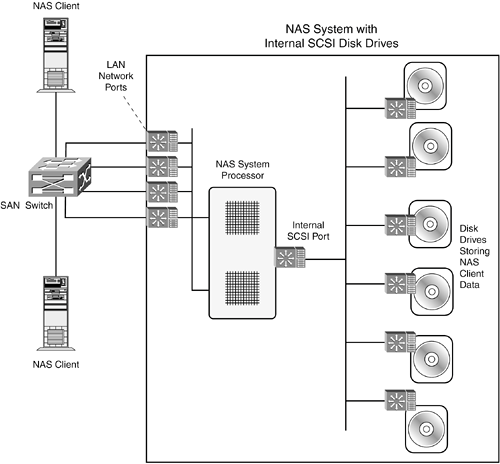 Mirrored SCSI disks are often used as boot disks for application servers that store their application data on a SAN. For example, database log files may be stored on mirrored high-performance SCSI disks, while data files are stored on SAN-based RAID arrays. Figure 7-4 shows a system connected to a SAN where the operating system is running on SCSI disks inside the system unit and where application data is being stored on a SAN. Figure 7-4. A System with Internal SCSI Boot Disks and Application Data Stored in a SAN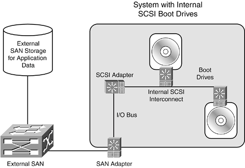 Parallel SCSI Storage in JBOD or RAID SubsystemsDisk subsystems place multiple disk drives in a cabinet with common power, cooling, and connectivity. JBOD, or just a bunch of disks, allows server systems to access individual disk drives, while RAID provides additional virtualization and redundancy algorithms to segregate or aggregate disk storage. The parallel SCSI interconnect is sometimes used inside SAN disk subsystems to connect SCSI disk drives to JBOD or RAID controllers. Subsystems with SCSI interconnects commonly have between five and ten parallel SCSI disks in a single enclosure. JBOD subsystems often allow disk drives to be removed and replaced without opening the cabinet. RAID, on the other hand, allows disk drives to be removed and replaced while the system is operating and data is being accesseda process called hot swapping. However, the parallel SCSI interconnectincluding power connectionswas not designed for easy removal and replacement of disk drives. Therefore, parallel SCSI RAID disk subsystems are usually designed with special backplanes and drive trays that allow disk drives to be removed and replaced easily. Essentially, the backplane of a SCSI disk subsystem replaces the cables and connectors of a parallel SCSI bus. Figure 7-5 illustrates the connectors used with device trays and backplanes with parallel SCSI. Figure 7-5. Backplane and Disk Tray Connectors for Parallel SCSI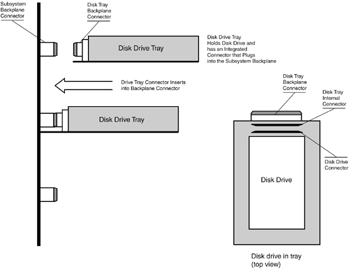 NOTE The trickiest part of this type of design for SCSI RAID is not the physical connectors, but the electrical "buffering" that needs to occur so that the removal or insertion of a new device does not cause errors on the bus, loss of data, or crashing systems. If you are not sure whether it is safe to remove a disk drive from a cabinet, don't do so until you find out or have a chance to quiesce the system. Host systems access storage in a SAN disk subsystem by the target/LUN addressing combination. The number of LUNs that can be accessed through a single subsystem port depends on the design and implementation of the subsystem controllers. For example, a small subsystem might limit the number of LUNs per port to eight, while a larger subsystem might allow 128 or more. JBOD subsystems allow access to individual disk drives without applying storage virtualization techniques. From the perspective of the SCSI logical process, the host initiator communicates more or less directly with a logical unit in a disk drive. The subsystem controller is responsible for converting serial SAN communications to parallel SCSI communications. The external LUN representing the logical unit for an internal disk drive and the internal parallel SCSI bus target/LUNs do not have to match. The JBOD controller is responsible for mapping the external and internal target/LUNs correctly. In that sense, the JBOD controller acts like a bridge, manipulating two different address spaces. Logical SCSI processes are independent of the connecting technology used, including scenarios involving JBOD subsystems implementing different external network and internal interconnect technologies. Therefore, while the connecting addresses may be different, the storing addresses used by SCSI processes are the same on both sides of the JBOD boundary. Figure 7-6 illustrates a SCSI logical connection from a host initiator in a SAN to a parallel SCSI disk drive in a JBOD subsystem. Figure 7-6. A SCSI Connection Using a JBOD Subsystem with Parallel SCSI Disks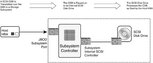
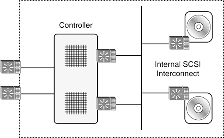
In contrast, RAID subsystems implement virtualization techniques that subdivide and aggregate storage on internal disk drives. With virtualization, the SCSI address spaces used by the internal storage controllers likely won't be the same as those used by host systems. Readers interested in virtualization will find much more information in Chapter 12, "Storage Virtualization: The Power in Volume Management Software and SAN Virtualization Systems." The SAN host initiator establishes a connection with a logical unit in the subsystem controller. Then an internal initiator in the controller completes the operation by establishing internal connections to one or more disk drives over the SCSI interconnect. SCSI communications between a host initiator and a SAN RAID subsystem with an internal parallel SCSI interconnect are pictured in Figure 7-7. Figure 7-7. A SAN RAID Subsystem with Parallel SCSI Disks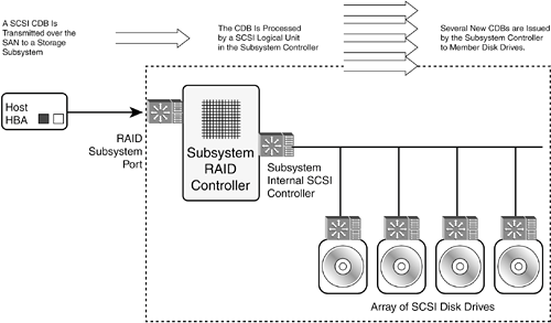 Dual-Controller Parallel SCSI ConnectionsDisk subsystems with internal parallel SCSI interconnects can support redundant paths to internal disk drives by connecting multiple controllers to internal SCSI buses. While it is not advisable to combine multiple controllers with off-the-shelf components on a parallel SCSI bus, it should not pose a problem as an engineered solution from a reputable storage products company. Figure 7-8 shows a disk subsystem with redundant internal connections over a parallel SCSI interconnect. Figure 7-8. A Disk Subsystem with Redundant Internal Parallel SCSI Connections
ATA: The Evolution of Desktop Storage to Lightweight Server StorageThe ATA interconnect was developed as an inexpensive storage interconnect for desktop and laptop systems. By virtue of the large numbers of personal computers sold, ATA is the most popular storage interconnect ever. Unlike parallel SCSI, which can be used for non-SCSI devices, ATA functionality has been restricted to disk drives, CD drives, and DVD drives. ATA has almost ridiculous connectivity restrictions, with a maximum of two devices per bus, reflecting its intent to support desktop machines at the lowest possible cost. Cable lengths are also far less than parallel SCSI, and unlike parallel SCSI, there are no external cable options. A Short History of ATAThe ATA interconnect is also referred to as Integrated Device Electronics (IDE). The technology has its roots in a project led by Compaq Computer along with Western Digital and Control Data's Imprimus disk drive division to create a PC hard drive with an integrated storage controller that served as an extension to the PC's IDE I/O bus. Products based on this work were introduced by Compaq in 1986, and in the years that followed, the approach was adopted and expanded upon by the rest of the industry. Eventually, the host system ATA controller circuitry was integrated on PC motherboards to eliminate the cost and footprint of a host adapter. The first ATA standard, titled the AT Attachment Interface for Disk Drives, was submitted to the ANSI T13 standard organization in 1990 and approved in 1994. Between 1990 and 1994, the disk drive industry created multiple proprietary extensions to the fledgling standard with names such as Fast ATA and Enhanced IDE. A revision to the original ATA specification, ATA-2, was published in 1996. This revision incorporated many of the proprietary extensions, including faster data transfer capabilities and several key usability features such as support for logical block addressing (LBA). A year later, the ATA-3 revision was published. It included Self-Monitoring Analysis and Reporting Technology (SMART), which is used to predict failures in disk drives. Concurrent with the development of ATA-2, an industry consortium called the Small Form Factor Committee developed a specification titled the ATA Packet Interface (ATAPI) for CD-ROMs (also known as SFF 8020), which was published in 1996. ATAPI was needed due to shortcomings in the ATA specification for supporting CD drives and other storage devices, such as tape drives. Essentially SFF 8020 defined a new protocol for non-disk drive operations over the ATA interconnect. Designed to use ATA controllers and cables, the ATAPI interface borrows heavily from SCSI for its logical structure. In 1998, the ATAPI specification combined with the ATA standards work in the ATA/ATAPI-4 standard. Another major breakthrough was the introduction of Ultra DMA transfer modes, which raised the maximum transfer rate to 33 MBps. To support the higher transfer rates, cyclic redundancy check (CRC) was introduced to ensure data integrity. In addition, an 80-conductor cable, which added ground conductors to the existing signal conductors, was specified to support higher transfer rates. In the year 2000, the transfer rates were doubled with the addition of two additional ultra DMA transfer modes. The current version is ATA/ATAPI-6, completed in 2002. It incorporates yet another transfer mode, which is capable of transfer rates up to 100 MBps. In addition, the LBA scheme was increased to accommodate higher-capacity drives. Table 7-2 lists the standards history of ATA/ATAPI.
ATA products are often referred to as Ultra ATA/XX, where XX is the maximum transfer rates of one of the ATA/ATAPI standards. For instance, an Ultra ATA/66 disk drive indicates that the drive is expected to be more or less compliant with the ATA/ATAPI-5 standard. New drives and motherboards are constantly being introduced with capabilities that anticipate unfinished standards. The industry uses these Ultra ATA names that indicate their transfer capabilities, which is what most people are most interested in. ATA ConnectionsATA buses are referred to as channels. An ATA channel can communicate with one or two devices. Obviously that limits the number of devices that can be assembled in a system. While it is certainly possible to put additional ATA controller adapters in a system, only so many slots are available. In addition, the ATA interconnect cannot be extended outside the system, as it can with parallel SCSI. In short, ATA was not designed to scale. All ATA PC system connectors (not including laptops) have the same 40-pin form factor. However, that does not mean that all cables are the same. Only 80-connector cables built for Ultra DMA operations support high-speed transfers. The 80-connector cables also have 40-pin connectors to be backward-compatible. Disk drives sold today come with the 80-connector cable, and replacement cables are inexpensive and readily available. The two devices connected to an ATA channel are configured as a master and a slave. Essentially, this is an arcane type of addressing and does not indicate a dependency between the devices. The determination of master or slave is made by positioning electrical jumpers on a set of pins on the drive. The jumpers can also be positioned to allow the master/slave selection to be made based on which connector a drive is attached to (this is called cable select). Cables sold with modern ATA hard drives are color-coded, as mandated by the standard, to facilitate their installation. The blue connector is intended to be used at the host controller connection, the black connector is to be used for a master drive, and the gray connector in the middle of the cable is to be used for a slave drive. ATA Interconnect PerformanceWhile the ATA interconnect has made rapid improvements in transfer rates over the years, approaching the transfer rates of parallel SCSI, the overall throughput of an ATA system is far less than a comparable SCSI system due to the lack of multitasking capabilities. Although the ATA standard has supported command queuing and overlapped I/O since the ATA/ATAPI-4 specification, these features have been mostly ignored by disk drive manufacturers. Realistically, command queuing and overlapped I/O are not essential features for most single-user systems. In an industry where cost savings are paramount, adding unnecessary features with extra cost is considered bad business. That said, the lack of performance features for ATA interconnects certainly limits their applicability for storage networking. Storage networks are built on the premise that multiple users and systems can access a centralized storage infrastructure. If the disk interconnect in a storage infrastructure cannot deliver data fast enough, it will become a bottleneck at some point. Another important consideration with ATA disk drives for storage networking is their expected duty cycle. While parallel SCSI and Fibre Channel disk drives are designed to run without pause for several years, desktop drives are not. That is not to say that ATA drives will all fail from round-the-clock use, but it is probably realistic to assume their failure rates will be higher than other more-robust drive designs. ATA drives are not poorly made, and shortcuts are not taken in reliability, but some additional technologies are used in SCSI and Fibre Channel drives to increase their reliability that are not used in ATA drives. ATA Network Storage ApplicationsThe ATA interconnect is obviously not optimized for storage network environments, but that does not mean it has no place in NAS or SAN products. In fact, ATA drives are already being used successfully in both NAS and SAN subsystems, and it is expected that they will continue to see more frequent use. But, unlike parallel SCSI, which works for practically any application, the selection of ATA in network storage needs to be more carefully evaluated to avoid unexpected performance problems. Servers with relatively light I/O requirements can utilize ATA drives effectively. E-mail servers and file servers for small office environments usually have light I/O requirements, as do many general-purpose Windows servers. There is no reason to overspend on storage for systems that do not need the performance. ATA drives can be characterized as having excellent capacity and mediocre performance. This combination is well suited for secondary storage applications such as disk-based backup, data archiving, hierarchical storage management (HSM), and Information Life Cycle Management. In general, these are not multitasking applications that need advanced I/O functions, but they do tend to consume lots of storage capacity. ATA Storage Network ConfigurationsATA disk drives are used in both NAS and SAN subsystems. In this section we'll look at using ATA drives in
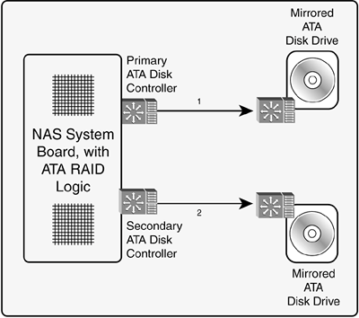
NAS Server with Internal ATA DisksMany NAS products have been designed with ATA disks in order to reduce costs. The design of these products is similar to any other NAS system: there are Ethernet ports for communicating with client systems and ATA interconnect ports to read and write data on internal disks. The ATA disks should be mirrored or striped with RAID to avoid risking data loss. When measuring the capacity of the system, be sure to calculate the usable capacity and not the raw capacity of the disks. NAS systems tend to grow. As users get used to them, they store increasing amounts of data on them, and therefore it's essential to provide a cushion for capacity growth. Unfortunately, ATA-based NAS systems may not be able to grow as fast as user capacity demand. The limitations of ATA connectivity are not conducive to expansion. Storage controller manufacturers began developing and selling ATA RAID a couple years ago, including integrated RAID on some PC motherboards. In general, ATA RAID is a very good idea in order to get redundant data protection along with some additional performance benefits. However, with only two devices per channel, it's not possible to create anything but small arrays with a handful of member disks. Still, a small array (including mirroring) is far better than no array at all. ATA RAID controllers are available with four channels supporting eight drives in an array, which is probably more than enough for small servers. Check with the NAS vendor about its disk/controller configuration to understand the expandability of its product. Figure 7-9 shows a simple NAS system with mirrored internal ATA disks. Figure 7-9. A NAS System Built with an ATA Interconnect
Storage manufacturers can do many different things when building their solutions. It is certainly possible to design large capacity NAS with ATA drives. The engineering effort involved is greater, but there are many possible ways to structure the connectivity to a large number of ATA drives. Network Appliance is an example of a company that has successfully designed and sold large-scale ATA-base NAS systems. ATA-Based SAN SubsystemsATA-based subsystems have also been introduced in recent years. Again, the idea is to use inexpensive ATA disk drives for servers with relatively light I/O requirements. The same performance and capacity scaling issues just discussed for ATA-based NAS apply to ATA-based SAN disk subsystems. ATA's two device limit per channel can be offset by using specialized connecting backplanes and controllers. Considering that most SAN disk subsystems have specialized backplanes and controllers already, this is not a major change. The difference is the use of the ATA interconnect channels, controllers, and protocol, which is different than the SCSI protocol used for SAN data transmissions. ATA-based SAN subsystems have external SAN ports to communicate with host system initiators. The controller assumes the role of all targets and logical units, including the logical unit's device controller and task manager. As SCSI logical operations and ATA operations are different, the internal ATA drives are virtualized by the subsystem controller. Commands are transferred to an ATA controller function, which issues commands to internal ATA drives. From the perspective of the ATA disk drives, the subsystem controller looks more or less like a controller in a PC system. That does not mean that the controller needs to contain PC components, but it has to replicate their role of the PC controller. Figure 7-10 shows a basic ATA-based SAN disk subsystem. Figure 7-10. A Basic ATA-Based SAN Disk Subsystem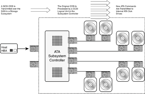 |
EAN: 2147483647
Pages: 184
