4.2 Planning the Disk Devices
4.2 Planning the Disk Devices
Frequently, the planning for the system disk(s) for both the initial Tru64 UNIX installation and the TruCluster Server implementation is overlooked. In fact, even experienced Systems Administrators fail to consider how big or little a partition on a system disk should be or what file system goes where until it is too late and they are already installing the system.
This lack of planning creates serious problems both in the short and long term. At best, you will end up rebuilding your system before you have any users and wasting valuable time in the process. At worst, you may have to have an extended amount of down time on a production system that is supposedly highly available. Bottom line: failure to plan is a poor practice.
We recognize that you are eager to start the implementation of TruCluster Server right away. But wait. Take a minute and think about what you are about to do.
Take your eagerness to start and channel it into planning the devices that you will use for the initial Tru64 UNIX system disk and the eventual TruCluster Server system disks.
4.2.1 Planning the Tru64 UNIX System Disk
Very often, we hear from Systems Administrators – both experienced and inexperience – that "Planning the initial Tru64 UNIX systems disk is not a big deal, especially if we will be installing and configuring TruCluster Server. After all, once the installation and configuration of TruCluster Server is complete, we'll never use that original Tru64 UNIX system disk again. In fact, we can just 'nuke' that old system disk and use that space for something constructive like another scratch area."
While it is true that the initial Tru64 UNIX system disk is used to build the TruCluster Server environment and then little used later, it should be retained and used as an "Emergency Repair" disk. Additionally, you can utilize the swap partition and/or configure a separate, local /tmp file system on this disk for use within the cluster to remove additional I/O from the shared buses, since both swap and /tmp are used on a per member basis as of this writing[1].
The Emergency Repair disk is essential to the repair and recovery of your cluster configuration should you encounter any problems in the future. For more information on the Emergency Repair disk, please refer to Chapter 22 on Cluster Maintenance and Recovery.
In any event, the importance in planning the Tru64 UNIX system disk should not be minimized. This system disk can still play an active role in the day-to-day operation of your cluster and can play an essential roll in the recovery of a cluster should problems occur.
As an aside, while this discussion and the discussions in the Tru64 UNIX Installation guides suggest using a local disk for the initial Tru64 UNIX installation, this is not a hard and fast rule. Disk devices on the shared bus may also be used for the initial Tru64 UNIX installation system disk.
4.2.1.1 How Much Space Is Enough?
Determining the disk partition sizes for each of the operating system's file systems is based on the software subsets that are to be installed and the usage of the file systems. The amount of space occupied by the software subsets can be easily determined ahead of time. This information is contained in the Release Notes for the version of the Tru64 UNIX that is to be installed. The amount of space to be used for each file system, based on actual daily usage, is usually discovered through experience so this information is usually harder to come by.
According to the Tru64 UNIX Installation guide, if you were to use a disk that is greater than 3 GB, the partition sizes used for: root (/) should be 384 MB, swap should be 384 MB, and /usr (including the /var) should be 2.235 GB. Based on the software subset sizes from the Tru64
UNIX Release Notes for version 5.1A, if all the software subsets from the Tru64 UNIX Operating System CD, the Associated Products Vol. 1 CD, and Associated Products Vol. 2 CD were to be installed, the amount of space used for the root (/) file system would be 122.35 MB, /usr would be 3004.86 MB, and /var would be 135.01 MB. We certainly do not recommend blindly installing everything from all of these CDs, but this information provides us with a baseline from which we have derived our own recommendations for partition sizes.
In the TruCluster Server Cluster Installation guide, HP strongly recommends, "that, unless prohibited by site policy, you load all subsets when installing the Tru64 UNIX system." Alternatively, you might consider installing only those software subsets that are needed to support your hardware configuration and/or that you expect your users will need based on the requirements for the implementation of your system. This approach to installing Tru64 UNIX can enhance basic system security and availability, and will be discussed in more depth in Chapter 5.
Our recommendations for the partitions used for the initial Tru64 UNIX disk are presented in Table 4-1.
| Disk Partition | Size | File System Type | File System | Usage by Tru64 UNIX or TruCluster Server |
|---|---|---|---|---|
| a | 512 MB | AdvFS | / | Tru64 UNIX |
| b | 2 or 3 times size or memory | swap | swap | Optionally Both |
| f | 2 GB | AdvFS | /tmp* | Optionally Both |
| g | 3 to 4 GB | AdvFs | /usr | Tru64 UNIX |
| h | 1 to 2 GB | AdvFS | /var | Tru64 UNIX |
We know, you are looking at this table and thinking to yourself that the sizes of these partitions are quite large. Well, given that 18 GB hard drives are now under $1,000, think of this as you would a rather inexpensive insurance policy – you may not think you need it but when you do, you will be quite happy to have it. Actually, the sizes of these system disk partitions are closely representative of implementations on clustered systems that we have seen.
4.2.1.2 Partitioning and Disk Layout
Obviously, the disk that you will use for the initial Tru64 UNIX installation will most likely differ from the disk we will use in our examples. This is to be expected, as you will probably use the latest and greatest disks available for your configuration. With this in mind, please use the partition sizes in our examples and recommendations as a starting point. Additionally, when considering your own Tru64 UNIX system disk layout, be sure to include space for other software components that you expect to install from HP, third party vendors, or Open Source.
Partitioning the initial Tru64 UNIX system disk can be performed either before you start the Tru64 UNIX installation or during the Tru64 UNIX installation. We will show you two ways in which this can be done, and will leave it to you to determine which way is easier and more efficient.
4.2.1.2.1 Partitioning Using the disklabel (8) Command
Partitioning the Tru64 UNIX system disk using the disklabel(8) command is performed before you actually start the installation of Tru64 UNIX. We know, you are asking yourself "How can you use a UNIX command like disklabel and not have Tru64 UNIX installed yet?" Let's look and see how we do this:
-
At the first prompt for the Installation of Tru64 UNIX, you would exit the Installation program to edit and write a new disk label on the disk that you will use for Tru64 UNIX.
Welcome to the Tru64 UNIX Installation Procedure This procedure installs Tru64 UNIX onto your system. You will be asked a series of system configuration questions. Until you answer all questions, your system is not changed in any way. ... o The "Exit Installation" option stops the installation and puts your system in single-user mode with superuser privileges. This option is intended for experienced UNIX system administrators who want to perform file system or disk maintenance tasks before the installation. This option may also be used for disaster recovery on a previously installed system. Remember, you can always get extra information by typing help. 1) U.S. English Installation 2) Installation with Worldwide Language Support 3) Exit Installation Enter your choice:3
-
At the shell prompt, set the appropriate terminal type and editor that you will be using to edit the disk label. In our example, we have found that the vt100 terminal type with the vi(1) editor work well.
# TERM=vt100; export TERM # EDITOR=/bin/vi; export EDITOR
-
The next step is to determine which disk to use. You should already have a good idea which disk to use. The issue is finding the right one. In this case, we will use dsk0 as it is the hard disk that is local to the server.
# /sbin/hwmgr –view device ... 67: /dev/disk/cdrom0c COMPAQ CD-224E bus-1-targ-0-lun-0 68:/dev/disk/dsk0c COMPAQ BD018635C4 bus-5-targ-0-lun-0 ...
-
Now that we know which disk to use, it's just a matter of editing and writing out the disk's label, right? Well, kind of. We know what the partition sizes in MB are for the system disk, but we still have to know what to change each partition size to in the disk label. Since the sizes for each partition are in 512-byte blocks, use the following algorithm to obtain the appropriate size for each partition:
Partition Size in MB * 2048 = Partition Size in 512-byte blocks
Here are a couple of examples:
If we need a partition that is 512 MB, let's say for root (/), we calculate the partition size as follows:
512 * 2048 = 1048576
If we need a partition that is 4.5 GB for swap[2], the partition size is calculated to be:
(4.5 * 1024) * 2048 = 9437184
We use the same algorithm for calculating the other three disk partitions that we will use on this soon-to-be system disk. See Table 4-2 for an example of the partitions that we plan to use for our local Tru64 UNIX system disk.
Table 4-2: Example Disk Partition Sizes Disk Partition
Size
File System Type
File System
(MB/GB)
(512-byte blocks)
a
512MB
1048576
AdvFS
/
b
4.5GB
9437184
swap
swap
e
3.9GB
8302104
unused
unused
f
2GB
4194304
AdvFS
/tmp[*]
g
4GB
8388608
AdvFS
/usr
[*]See Chapter 21 on configuring a separate /tmp file system.
-
Now that we have identified the disk that we will use and the sizes of each partition, it comes down to writing a default label on the disk before we can edit this label.
# disklabel –r –w dsk0
-
Finally, we edit the disk label for this disk and write it out to the disk itself.
# disklabel –e –r dsk0
-
To restart the Installation of Tru64 UNIX, it is just a matter of executing the command restart.
# cd / # restart
4.2.1.2.2 Partitioning Using the Disk Configuration Application
If you are performing a Full Installation of Tru64 UNIX with the graphical user interface (GUI), custom modification of the partitions of the system disk can be accomplished without exiting the installation. How? From the installation's GUI, view the selected disk partition information by clicking on the "Edit Partitions…" button on the Custom File System Layout box to open the Disk Configuration application. See Figure 4-1 for an example.
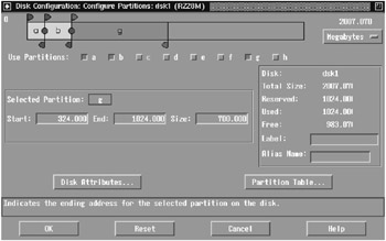
Figure 4-1: The Disk Configuration (diskconfig (8)) Program
The Disk Configuration application can also be run outside of the Tru64 UNIX Installation program by executing the command /usr/sbin/diskconfig. For more information on the diskconfig (8) command, please see its reference page.
4.2.1.2.3 The Disk Label After the Tru64 UNIX Installation
Using our example, after the Full Installation of Tru64 UNIX, the disk label for our new system disk should look something like this:
# disklabel dsk0 | grep -p "8 part" 8 partitions: # size offset fstype fsize bsize cpg # ~Cyl values a: 1048576 0 AdvFS # 0 - 206* b: 9437184 1048576 swap # 206*- 1857* c: 35565080 0 unused 0 0 # 0 - 7000 d: 0 0 unused 0 0 # 0 - 0 e: 8302104 10485760 unused 0 0 # 1857*- 3491* f: 4194304 18787864 unused 0 0 # 3491*- 4316* g: 8388608 22982168 AdvFS # 4316*- 5967* h: 4194304 31370776 AdvFS # 5967*- 7000
Notice that disk partitions "e" and "f" still have an fstype of unused. At this time, we have only "prepared" the disk to have a separate /tmp file system. See Chapter 21 on creating a cluster member's /tmp as a separate file system.
4.2.2 Planning the Swap Areas for the Cluster
When a cluster member is initially configured, by default, its primary swap is located on the "b" partition of the same hard disk as the cluster member's boot_partition. Normally this is also on the cluster's shared bus, which has its advantages especially when it comes to high availability of the swap device and the ability to save the crash dump of a cluster member that is down.
Configuring swap on a shared bus, however, can have performance consequences. For example, if an individual cluster member starts to aggressively use its swap space, all the I/O would go across the shared bus and potentially impact the other cluster member(s). While this is not an ideal condition, we should emphasize that with a properly configured system, aggressive usage of the swap space should occur very rarely.
If a member's swap space is configured on the shared bus, the Device Request Dispatcher (DRD) server for the disk where the swap partition resides does not necessarily have to be located on the cluster member that is actually using the swap space. This situation could occur if the host bus adapter (HBA) or cable from the member to the storage fails and is an excellent automatic recovery scenario from a pure high availability standpoint. If a cluster member starts to use the swap space aggressively while the DRD server is not local to the member, however, all the swap-related I/O would be routed through the cluster interconnect. This scenario, while extremely rare, could saturate the cluster interconnect and impact the entire cluster.
In planning your cluster, and in planning the swap for your cluster, you must consider issues of high availability as well as performance. You also must examine what is an acceptable failure scenario for the applications and the users on the cluster. By default, the installation of a TruCluster Server environment attempts to provide high availability for as much as possible, including swap. In our two examples, this high availability of swap has consequences for a system that's not properly configured. The consequences relate to the performance and availability of the cluster itself. This underscores the importance of designing your cluster carefully and thoughtfully considering the applications and the user community that the cluster will be supporting.
Imagine that instead of having each cluster member's swap partition on the shared bus, it resides on a disk locally accessible to each member. Let's analyze the pros and cons of this arrangement.
-
The pros of having swap on a locally accessible disk:
-
The swap-related I/O is not on the shared bus.
-
The swap-related I/O will not be routed through the cluster interconnect.
-
The swap activity of one cluster member has little or no impact on any of the other cluster members because the resources involved are no longer shared.
-
The swap-related I/O is now local to the server that is doing the swapping. From a performance standpoint, this should give better performance.
-
-
The cons of having swap on a locally accessible disk:
-
The swap for the cluster member is no longer highly available. If swap is not available for whatever reason (i.e., the HBA fails), the cluster member may crash.
-
Should a cluster member crash and is down, you will not be able to access the crash dump for that member from any other cluster member. This information would be available only after the cluster member reboots.
-
Another option to consider is to keep a small primary swap partition on the member boot disk that is large enough to hold a partial dump and add a larger secondary swap partition on a bus that is accessible only to the cluster member.
The decision on where you have each cluster member's swap partition should ultimately be based on your cluster's availability criteria. If you decide to have each cluster member's swap on a local disk, please refer to Chapter 21 on how to implement this.
One last note about the swap partition: regardless of where the primary swap partition physically resides, we recommend that if you are using the eager swap mode algorithm (the default), you should allocate a swap space of at least two to three times the size of the cluster member's physical memory, which can be distributed on one or more swap partitions. Also, should you later increase the memory of a server, don't forget to increase the size of the swap space.
If your cluster members are Very Large Memory (VLM)[3] systems and used for a specific application like a database, please refer to the application vendor's documentation on how much swap space is required and which swap algorithm to use. Based on this information, please plan accordingly. If the swap algorithm that you are to use is lazy mode or deferred mode, your swap space requirements can vary widely, from as little as configuring swap to contain only a partial dump to three times the size of memory.
4.2.3 Hardware Storage Configuration
When you think about a TruCluster Server environment, a couple of the things that come to mind are the Cluster File System, a shared bus, and how everything magically works together. TruCluster Server may not be magic, but it is very cool technology. It is a technology that can easily be aligned with your company's business goals if those goals include high availability and scalability.
We believe that if you have chosen to deploy a TruCluster Server implementation, you have done so with both high availability and scalability in mind. In order to implement TruCluster Server, in addition to the software "bits and bytes," the servers, adapter cards, hubs, switches, cluster interconnects, and cables, we need storage - storage for the cluster's system disks and for the users applications and data. We also recommend that if you are going to deploy any type of highly available cluster, please use RAID-based storage for the protection and availability it provides.
The storage subsystem is an integral part of any TruCluster Server implementation. In this section, we will be discussing the hardware RAID array storage that is necessary to support TruCluster Server in a highly available configuration.
| Note | While hardware-based RAID is generally accepted as the better performing RAID solution, there is a software-based RAID option known as the Logical Storage Manager (LSM) that can be used as a lower-cost alternative. See Chapter 14 for more information. |
4.2.3.1 Supported Hardware RAID Array Controllers
Table 4-3 provides a list of HP StorageWorks hardware RAID array controllers, along with the each controller's minimum firmware requirements, that support the implementation of TruCluster Server V5.1A.
| Storage Controller | Minimum Firmware Version |
|---|---|
| HSZ40 | Version 3.7 or higher |
| HSZ50 | Version 5.7 or higher |
| HSZ70 | Version 7.7 or higher |
| HSZ80 | Version 8.3-1 or higher |
| HSG60 | Version 8.5 or higher |
| HSG80 | Version 8.5 or higher |
For more detailed information and restrictions on the usage of these hardware storage controllers, we highly recommend reviewing the TruCluster Server Cluster Release Notes, TruCluster Server Cluster Hardware Configuration guide, and the TruCluster Server Cluster Installation guide for the version that you will be implementing. For more information on configuring the storage controller that you expect to use, please refer to the StorageWorks Installation and Configuration Guide for Compaq Tru64 UNIX that comes with your controller.
4.2.3.2 Transparent Failover Mode vs. Multi-bus Failover Mode
Before we start our discussion on what a failover mode is, let's assume that we have a pair of RAID array storage controllers from those listed in Table 4-3 and configured in a dual-redundant configuration. A dual-redundant configuration means that if one controller should fail, the other controller picks up the slack, and the cluster continues to operate without interruption.
For the purposes of this discussion, we will be using the HSG80 controller to represent all the StorageWorks RAID array controllers that are supported for a TruCluster Server configuration. While all of the RAID array storage controllers that we have listed in Table 4-3 are capable of Transparent Failover Mode, only the HSZ70, HSZ80, HSG60, and HSG80 storage controllers are capable of Multi-bus Failover Mode.
What is failover mode? Failover mode is a way to keep the shared storage array available to the attached servers or hosts if one of the storage controllers goes down or becomes unresponsive. Failover mode provides for the remaining storage controller to take control and allows the storage array to remain available.
There are two different failover modes: Transparent and Multi-bus. Transparent failover is handled by the remaining controller and as such is "transparent" to the hosts connected to the storage. The hosts handle multi-bus failover.
The primary characteristics of transparent failover mode include:
-
The hosts attached to the storage are unaware that a failover has occurred.
-
The logical storage units presented to the hosts, and managed by the controllers, are divided between controller host ports 1 and 2. Storage units 0-99 are accessible through port 1 with storage units 100-199 accessible through port 2.
-
In a dual-redundant controller configuration, only host port 1 on one of the controllers will be active with the host port 1 on the other controller in standby. The same is true of host port 2. Only one host port 2 on one of the controllers will be active with the host port 2 on the other controller in standby. Please see Figure 4-2 for an illustration of this configuration.
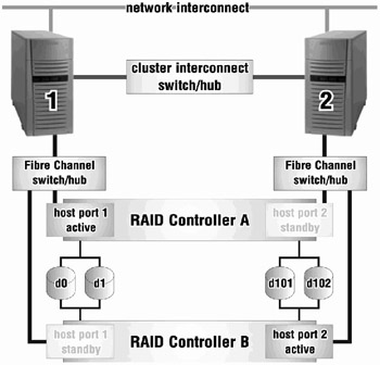
Figure 4-2: RAID Controller Transparent Failover
How does transparent failover work? If one of the two controllers fails, then both ports on the remaining controller become active and serve out all the storage units.
While transparent failover compensates for the failure of a controller, it does not address the failure of a host bus adapter in the server or the storage link.[4] This is where multi-bus failover really shines. Multi-bus failover compensates for the failure of a controller, host bus adapter, or storage link.
Some of the characteristics of multi-bus failover mode include:
-
All storage units are accessible through all host ports of the controllers (unlike transparent failover).
-
Each host has at least two paths to the storage units. This is accomplished by using multiple host bus adapters in each host.
-
All hosts attached to the storage must have the appropriate operating system software that supports multi-bus failover.
-
The hosts control the process of moving the storage units from one controller to another during a failover scenario. When access to storage units from one path fails, the host(s) issues the command to access the storage units through another path. Please see Figure 4-3 for an illustration of this configuration.
-
Although all storage units are accessible through all host ports on the controllers, you can specify which storage units are normally serviced by a specific controller.
-
The I/O load from a host can be redistributed between controllers.
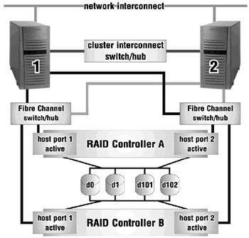
Figure 4-3: RAID Controller Multi-bus Failover
4.2.3.3 Clustering in a Heterogeneous SAN Environment
The HSG60 and the HSG80 RAID array controllers are by their nature Storage Area Network (SAN) ready controllers. This means that you can attach multiple, heterogeneous servers to this storage array by connecting them to a SAN Fibre Channel Switch that is a part of this type of storage configuration. While this can potentially provide a huge benefit to the data center by consolidating storage for many servers, it can also be quite dangerous for a TruCluster Server configuration if it is not well thought out and planned.
Although we will not describe in detail how to deploy a cluster in a heterogeneous SAN environment – we will leave this for another book – we can say that this is entirely possible and very easy to implement. We will also provide warnings on deploying such a configuration.
When deploying multiple TruCluster Server environments on one SAN, use selective storage presentation[5] and, although not necessary, try to create separate zones (for each cluster) at the Fibre Channel Switch.[6] As TruCluster Server uses persistent reservations on all the storage devices that it sees, we want to protect storage used for one cluster from being accessed by another cluster.
When deploying other servers (i.e., HP-UX, Solaris, Windows 2000, etc.) in addition to a TruCluster Server into a SAN environment, there are several considerations:
-
The storage controllers must be configured for multi-bus failover mode and all servers should have multiple host bus adapters.
-
All servers must also have installed software that supports multi-bus failover. Tru64 UNIX and TruCluster Server automatically have this software. For other servers, HP StorageWorks has a product called SecurePath that provides these "bits and bytes."
-
Zoning at the Fibre Channel Switch should be done for each class of servers. There should be separate zones for HP-UX, Solaris, Windows 2000, and TruCluster Server. This helps prevent servers of different classes from interfering with each other's storage.
-
Selective storage presentation should always be used. Again, this prevents servers from accessing each other's storage within the same zone.
4.2.3.4 Selective Storage Presentation
What is selective storage presentation? Selective storage presentation is a feature of the HSG60 and the HSG80 controllers that allows specific hosts to access specific storage units and is a means by which we can restrict host access to storage units.
If you have more than one cluster connected to a storage subsystem, or if you have other servers that are not part of a cluster connected to this same storage subsystem, then the access path to the individual storage units must be specified. This is accomplished through selective storage presentation.
Selective storage presentation is supported in Transparent Failover Mode or Multi-bus Failover Mode.
How do you use selective storage presentation for a cluster? The process is very straightforward.
-
From each server's console, determine the World Wide Name or World Wide ID (wwid) for the host bus adapter(s) that are connected to the storage subsystem.
P00>>> wwidmgr -show adapter item adapter WWN Cur. Topo Next Topo pga0.0.0.7.1 - Nvram read failed [ 0] pga0.0.0.7.1 2000-0000-c924-7c58 FABRIC UNAVAIL [9999] All of the above.
The "Nvram read failed" message indicates that the host bus adapter's (a KGPSA) NVRAM has not been initialized or formatted. The "Next Topo" field shows up as UNAVAIL because the host bus adapter has an unformatted NVRAM. In a cluster configuration, as the server and the storage subsystem will be operating in fabric mode, both messages can be safely ignored.
Even though these messages are benign, they can be corrected using the "wwidmgr" command with the "-set adapter" option at the SRM console prompt:
P00>>> wwidmgr -set adapter -item 9999 -topo fabric P00>>> wwidmgr -show adapter item adapter WWN Cur. Topo Next Topo [ 0] pga0.0.0.7.1 2000-0000-c924-7c58 FABRIC FABRIC [9999] All of the above.
In this example, we obtained the wwid for the host bus adapter for only one of the cluster's servers. Use this same process for each server in the cluster to determine the wwid for each host bus adapter connected to the storage subsystem
-
Next, connect to the HSG60/HSG80 controller's command console and determine the host connections for the adapters attached to the storage subsystem.
HSG> show connections Connection Name Operating system Controller Port Address Status !NEWCON1 WINNT THIS 1 011600 OL this 0 HOST_ID=2000-0000-C924-7C58 ADAPTER_ID=1000-0000-C924-7C58 !NEWCON2 WINNT OTHER 2 011600 OL other 100 HOST_ID=2000-0000-C924-7C58 ADAPTER_ID=1000-0000-C924-7C58 !NEWCON3 WINNT THIS 1 011700 OL this 0 HOST_ID=2000-0000-C924-3514 ADAPTER_ID=1000-0000-C924-3514 !NEWCON4 WINNT OTHER 2 011700 OL other 100 HOST_ID=2000-0000-C924-3514 ADAPTER_ID=1000-0000-C924-3514
Notice that by default, the "Operating system" is noted to be WINNT even though we are using Tru64 UNIX. We will change that to something more meaningful later in our discussion, but we are currently interested in the address of the HOST_ID. It should be the same as the wwid of the host bus adapter(s) as seen from the server's console.
Let's change the operating system type to Tru64 UNIX and make the connection names more meaningful.
HSG> set !NEWCON1 TRU64_UNIX HSG> set !NEWCON2 TRU64_UNIX HSG> set !NEWCON3 TRU64_UNIX HSG> set !NEWCON4 TRU64_UNIX HSG> rename !NEWCON1 MOLR1A1 HSG> rename !NEWCON2 MOLR1B2 HSG> rename !NEWCON3 SHER1A1 HSG> rename !NEWCON4 SHER1B2
That's better, now let's see what we have in terms of host connections.
HSG> show connections Connection Name Operating system Controller Port Address Status MOLR1A1 TRU64_UNIX THIS 1 011600 OL this 0 HOST_ID=2000-0000-C924-7C58 ADAPTER_ID=1000-0000-C924-7C58 MOLR1B2 TRU64_UNIX OTHER 2 011600 OL other 100 HOST_ID=2000-0000-C924-7C58 ADAPTER_ID=1000-0000-C924-7C58 SHER1A1 TRU64_UNIX THIS 1 011700 OL this 0 HOST_ID=2000-0000-C924-3514 ADAPTER_ID=1000-0000-C924-3514 SHER1B2 TRU64_UNIX OTHER 2 011700 OL other 100 HOST_ID=2000-0000-C924-3514 ADAPTER_ID=1000-0000-C924-3514
-
Now that we know the connections from the cluster nodes to the storage, for every storage unit that we create for the cluster, we would set the accessibility so that only the nodes of the cluster have access to this storage. First, we would disable access to all connections; then selectively enable access to only those connections connected to the cluster nodes.
HSG> add unit d101 m2 partition=1 disable_access_path=all
HSG> show d101 LUN Uses Used by ----------------------------------------------------------------------------------------- D101 M2 (partition) LUN ID: 6000-1FE1-0001-6950-0009-1420-0755-0047 IDENTIFIER = NONE Switches: RUN NOWRITE_PROTECT READ_CACHE READAHEAD_CACHE WRITEBACK_CACHE MAX_READ_CACHED_TRANSFER_SIZE = 32 MAX_WRITE_CACHED_TRANSFER_SIZE = 32 Access: None State: ONLINE to the other controller Size: 2133378 blocks Geometry (C/H/S): ( 420 / 20 / 254 )
HSG> set d101 enable_access_path=(MOLR1A1,MOLR1B2,SHER1A1,SHER1B2)
HSG> show d101 LUN Uses Used by -------------------------------------------------------------------------------------- D101 M2 (partition) LUN ID: 6000-1FE1-0001-6950-0009-1420-0755-0047 IDENTIFIER = NONE Switches: RUN NOWRITE_PROTECT READ_CACHE READAHEAD_CACHE WRITEBACK_CACHE MAX_READ_CACHED_TRANSFER_SIZE = 32 MAX_WRITE_CACHED_TRANSFER_SIZE = 32 Access: MOLR1A1, MOLR1B2, SHER1A1, SHER1B2 State: ONLINE to the other controller Size: 2133378 blocks Geometry (C/H/S): ( 420 / 20 / 254 )
From this example, only the individual cluster nodes, sheridan and molari, have selective access to storage unit D101.
Another way to do selective storage presentation is to set the offsets for each host connection. Setting offsets establishes the beginning of the range of storage units that a host connection can access. For the purposes of simplicity of design and implementation, we do not recommend that you use offsets in a TruCluster Server configuration – especially if you are dealing with multiple clusters attached to one storage subsystem. For more information on using offsets, please refer to Chapter 1 of the HSG80 ACS Solution Software – Installation and Configuration Guide.
4.2.4 Hardware RAID Configuration
By selecting TruCluster Server, one assumes that high availability is of concern. For this reason, we recommend using a RAID solution for root ((/) or cluster_root), /usr (or cluster_usr), and /var (or cluster_var) as well as any other file systems that your requirements deem critical. In this section, we will discuss configuring RAID 1, RAID 0+1, and RAID 5 using HP StorageWorks HSZ or HSG controllers to support the cluster systems disks in a TruCluster Server configuration.
Before we get into the details of why you may want to use one level of RAID over another and the implementation process, let's go over a generalized procedure that will be used to create and make available multiple storage units from a RAID set.
-
Creating and initializing the RAID set
-
Partitioning the RAID set
-
Creating the storage units
-
Configuring the storage units
As we provide examples on how to build the cluster's system disks using the different levels of RAID, this generalized procedure will become more specific.
RAID sets can be very large, but since modern individual disk drives are very large, the devices that are required for the cluster's system disks tend to be small by comparison, so storage set partitioning at the controller can be useful. Storage set partitioning is a means of dividing a storage set into smaller pieces. It is these smaller pieces that are presented to the hosts as separate storage units of the appropriate size.
The following are limitations on partitioning of storage sets or RAID sets:
-
Each partition is created as a percentage of the RAID set or storage set.
-
The maximum number of partitions per storage set for the HSZ70, HSZ80, HSG60, and HSG80 controllers is eight.
-
The maximum number of partitions per storage set for the HSZ40 and the HSZ50 controllers is four.
-
In transparent failover mode, partitions from the same storage set must be on the same host port.
-
On HSZ controllers, storage partitioning is only supported in transparent failover mode. On HSG controllers, storage partitioning is supported in both transparent failover mode and multi-bus failover mode.
-
In multi-bus failover mode, partitions from the same storage set must be on the same controller.
-
Unless within a single TruCluster Server environment, separate storage partitions from the same storage set or RAID set should not be used between different individual systems.
At their simplest, the disks and UNIX partitions required to build a two-node cluster are illustrated in Table 4-4.
| Disk | Partition or File System |
|---|---|
| dsk1 | a member1 boot_partition |
| b member1 swap partition | |
| h member1 cnx partition | |
| dsk2 | a member2 boot_partition |
| b member2 swap partition | |
| h member2 cnx partition | |
| dsk3 | h cnx partition |
| dsk4 | b cluster_root |
| g cluster_usr | |
| h cluster_var |
Please note that the quorum disk requires its own disk without anything else on it. Is this necessary? Absolutely! For more information on the quorum disk and when to use a quorum disk, see Chapter 17.
Now, let's look at specifically what we will need in terms of disks, partitions, and partition sizes for a two-node cluster. Table 4-5 not only illustrates what is needed for a two-node cluster, but it also provides the information necessary to grow and expand this cluster.
| Disk | UNIX Parition | Size | File System Type | File System | AdvFS Domain | |
|---|---|---|---|---|---|---|
| dsk1 | a | 256 MB | AdvFS | member1 boot_partition | root1_domain | The "b" partition(s) used for swap are 1.5 GB(the size of memory) if the primary swap is on the local disk. In our example, as we are using eager swap, and if there is no local disk for primary swap, the "b" partition is three times the size of memory. |
| b | 1.5 GB or 4.5 GB | swap | swap | swap | ||
| h | 1 MB | cnx | n/a | n/a | ||
| dsk2 | a | 256 MB | AdvFS | member2 boot_partition | root2_domain | |
| b | 1.5 GB or 4.5 GB | swap | swap | swap | ||
| h | 1 MB | cnx | n/a | n/a | ||
| dsk3 dsk4 | a | 256 MB | unused | n/a | n/a | dsk3 and dsk4 are created for future cluster members 3 and 4 . This is to support the expected expandability of the cluster. |
| b | 1.5 GB or 4.5 GB | unused | n/a | n/a | ||
| h | 1 MB | unused | n/a | n/a | ||
| dsk5 | h | 1 MB | cnx | quorum disk | quorum disk | |
| dsk6 | a | 512 MB | AdvFS | / | cluster_root | |
| g | 4.0 GB | AdvFS | /usr | cluster_root | ||
| H | 4.0 GB | AdvFS | /var | cluster_var |
It is important to note that before you start to install Tru64 UNIX on the local disk, all RAID storage sets should be properly configured and initialized. The following sections will detail ways to configure and initialize different types of RAID storage sets to support a cluster's system disks.
4.2.4.1 RAID 1 vs. RAID 0+1 vs. RAID 5 for the Cluster's System Disks
In this section, we will briefly discuss what RAID 1, RAID 0+1, and RAID 5 are and why you might want to use one RAID level over another in a cluster configuration.
-
RAID 1
RAID level 1 is also known as mirroring. The redundancy of mirroring is exactly what happens with the data. All data is simultaneously written to two of more drives at the same time. From a performance standpoint, access to data is faster on reads than on writes; however, should a drive ever fail in a RAID 1 set there should be no loss of data. The minimum number of drives to implement a RAID 1 set is two. The effective storage utilization space is approximately the size of one drive in a two drive RAID 1 set.
-
RAID 0+1[7]
This is a combination of mirroring (RAID level 1) and striping (RAID level 0). This provides for the complete redundancy of mirroring with the write performance that comes with striping the data across all drives. A RAID 0+1 set offers the highest level of redundancy with the greatest level of performance but at a higher cost in terms of hard drive spindles. The minimum number of drives to implement a RAID 0+1 set is four. The effective storage utilization space is approximately the size of two drives of the four drive RAID 0+1 set.
-
RAID 5
RAID level 5 stripes data across all disks, but it also distributes parity among all the disks in the RAID 5 set. The parity information provides for recovery of the RAID set should any single drive fail. Performance on writes is decent while performance on reads is just okay. The minimum number of drives to implement a RAID 5 set is three. Optimally, we recommend that three to six drives be used for a RAID 5 set. The effective storage utilization space is approximately the size of all the drives in the RAID 5 set less one drive, which is necessary for parity. In sum, while RAID 5 may not be the best in terms of performance, it is the most cost effective.
Now that we know about the RAID levels that provide for high availability of the storage, why might one be preferable to another in a TruCluster Server configuration?
This decision should be made based on requirements versus cost. All three RAID levels discussed provide for high availability but at varying costs and performance levels. If cost is not an issue, we recommend using RAID 0+1 for everything. Again, this provides for the highest availability at the greatest performance. If cost is an issue and you want a sound foundation upon which to build your cluster, we recommend using RAID 1 for the system disks and RAID 5 for all the users' file systems.
Bottom line: deciding which RAID level to use is situational. What we can do here is offer ideas for the various implementations of the cluster system disks on the different levels of RAID.
4.2.4.2 Planning for Future Cluster Expansion
In planning for your cluster, plan not only for the impending implementation of your cluster but also for its future expansion. If you plan for the future expansion of your cluster, then increasing the number of cluster members is easy, straightforward, and should not take any longer than 45 minutes per additional cluster node.
Okay, so does this have anything to do with building RAID sets or are the authors a little "whacked?" There is, as they say, a method to our madness. The upcoming sections on building RAID sets for the cluster's system disks will include building an extra amount of storage for cluster nodes that may be added six months or a year down the line. It is prudent to build all your storage units sooner rather than later.
4.2.4.3 Building a RAID 5 Set for the Cluster's System Disks
In this section, we will build all the storage units necessary to support a cluster's system disks using a RAID 5 set. RAID 5 provides the best availability at the best cost per byte of storage.
As disk drives tend to be very large, any RAID set will generally be very large. This is especially true with the smallest RAID 5 set. In general, with the exception of the space requirement for swap, the amount of space to support a cluster's system disks is relatively small. While some Systems Administrators would say that this is a good problem to have, others would cringe at the thought of wasting valuable disk space.
In our example of building a RAID 5 set for the cluster's system disk, we will be using 18 GB drives – three 18 GB drives.
-
Create and initialize the RAID 5 set.
As you can see, building a three disk RAID 5 set is a relatively easy operation.HSG> add raidset r0 disk10000 disk20000 disk30000
>HSG> initialize r0 save_configuration
After the RAID set is created and as it is initialized, the RAID configuration is actually saved to the RAID set using the save_configuration flag. It is important to save the RAID configuration information to a RAID set on the controller so that if a catastrophic failure is encountered and both storage controllers are lost at the same time, we can easily recover all the RAID sets without any loss of data. How is this done? After replacing the failed storage controllers, the recovery of the saved RAID configuration information is read off the RAID set to which it was originally saved.
-
Partition the RAID 5 set.
This next step of partitioning the RAID 5 set takes planning. It is here that we use the information from Table 4-5 to determine what percentage of the effective storage utilization space of the RAID 5 set each partition will be. As the effective storage utilization space for a three drive (each with a 18 GB drive) RAID 5 set is approximately 36 GB, each partition size is a percentage of this number.
HSG> create_partition r0 size=14 HSG> create_partition r0 size=14 HSG> create_partition r0 size=14 HSG> create_partition r0 size=14 HSG> create_partition r0 size=1 HSG> create_partition r0 size=largest
In this example, the first partition is created with a partition size of 14% of 36 GB. The size=largest allows us to utilize all the remaining space on the drive without having to set a percentage.
-
Create the partitioned storage units.
Now that the RAID 5 set has been partitioned, each new storage unit is created from each storage partition. These storage units are presented to the hosts – the cluster members.
HSG> add unit d1 r0 partition=1 disable_access_path=all HSG> add unit d2 r0 partition=2 disable_access_path=all HSG> add unit d3 r0 partition=3 disable_access_path=all HSG> add unit d4 r0 partition=4 disable_access_path=all HSG> add unit d5 r0 partition=5 disable_access_path=all HSG> add unit d6 r0 partition=6 disable_access_path=all
IMPORTANT As each new storage unit is created, we disable the access path to all hosts. This prevents accidental access by a host connected to the storage subsystem.
-
Configure the partitioned storage units.
In this final step, we set the identifier for each new storage unit and selectively enable the access path to allow only the host connections for each of the cluster nodes.
HSG> set d1 identifier=1 enable_access_path=(MOLR1A1,MOLR1B2,SHER1A1,SHER1B2) HSG> set d2 identifier=2 enable_access_path=(MOLR1A1,MOLR1B2,SHER1A1,SHER1B2) HSG> set d3 identifier=3 enable_access_path=(MOLR1A1,MOLR1B2,SHER1A1,SHER1B2) HSG> set d4 identifier=4 enable_access_path=(MOLR1A1,MOLR1B2,SHER1A1,SHER1B2) HSG> set d5 identifier=5 enable_access_path=(MOLR1A1,MOLR1B2,SHER1A1,SHER1B2) HSG> set d6 identifier=6 enable_access_path=(MOLR1A1,MOLR1B2,SHER1A1,SHER1B2)
If only one cluster is connected to the storage subsystem, it is unnecessary to disable and then re-enable the access path to the storage. Disabling the access path and then selectively enabling the access path for certain host connections is an example of selective storage presentation. The default flag setting when you create any storage unit is to enable_access_path=all – or enable access for all host connections.
4.2.4.4 Building a RAID 1 Set for the Cluster's System Disk
In the previous section, we built all the storage units necessary to support a cluster's system disks; in this section, we will build only the majority of these storage units. As we are using eager swap allocation, we recommend that you allocate three times the size of memory for a swap partition. We assume that the primary swap partitions for each cluster member will be on other drives.[8] The swap space set aside when we configure these storage units will be the same size as memory for each cluster member and may eventually be used as the secondary swap partition for each cluster member.
Using RAID 1 for the cluster's system disks provides a sound foundation for availability in a cluster. While it is not the best performing for writes in the event a disk drive in a RAID 1 fails, you can be reasonably assured that your data will be safe.
Similar to our example of building a RAID 5 set, we will be use 18 GB drives – two 18 GB drives--in this example of building a RAID 1 set for the cluster's system disks.
-
Create and initialize the RAID 1 or Mirror set.
HSG> add mirrorset m0 disk10100 disk20100
HSG> initialize m0 save_configuration
Be sure to use the save_configuration flag to preserve RAID configuration information on the Mirror set.
-
Partition the RAID 1 or Mirror set.
Partitioning is performed in precisely the same way as in the previous example using the RAID 5 set. The only difference is that the partition sizes are different. Instead of having an effective storage utilization space of 36 GB as with the RAID 5 set, we have an effective storage utilization space of only 18 GB. As the size is a percentage of the space available, it makes sense that the percentages would differ given the different space availability and especially given that we do not account for all the swap space.
HSG> create_partition m0 size=12 HSG> create_partition m0 size=12 HSG> create_partition m0 size=12 HSG> create_partition m0 size=12 HSG> create_partition m0 size=1 HSG> create_partition m0 size=largest
-
Create the partitioned storage units.
HSG> add unit d11 m0 partition=1 disable_access_path=all HSG> add unit d12 m0 partition=2 disable_access_path=all HSG> add unit d13 m0 partition=3 disable_access_path=all HSG> add unit d14 m0 partition=4 disable_access_path=all HSG> add unit d15 m0 partition=5 disable_access_path=all HSG> add unit d16 m0 partition=6 disable_access_path=all
-
Configure the partitioned storage units.
HSG> set d11 identifier=11 enable_access_path=(MOLR1A1,MOLR1B2,SHER1A1,SHER1B2) HSG> set d12 identifier=12 enable_access_path=(MOLR1A1,MOLR1B2,SHER1A1,SHER1B2) HSG> set d13 identifier=13 enable_access_path=(MOLR1A1,MOLR1B2,SHER1A1,SHER1B2) HSG> set d14 identifier=14 enable_access_path=(MOLR1A1,MOLR1B2,SHER1A1,SHER1B2) HSG> set d15 identifier=15 enable_access_path=(MOLR1A1,MOLR1B2,SHER1A1,SHER1B2) HSG> set d16 identifier=16 enable_access_path=(MOLR1A1,MOLR1B2,SHER1A1,SHER1B2)
The two previous bullet points are exactly the same as in the RAID 5 example.
4.2.4.5 Building a RAID 0+1 Set for the Cluster's Systems Disk
In this section, we will build all the storage units necessary to support a cluster's system disks using a Striped Mirror set (aka a RAID 0+1 set). RAID level 0+1 provides the highest availability with the greatest performance but at a cost.
As with our RAID 5 example, the smallest RAID 0+1 set is actually very large. It is large enough to support all our space requirements for the cluster's system disk – including our large swap space recommendation.
Again, as with our example of building a RAID 5 set, we will use four 18 GB drives to build our RAID 0+1 set to support the storage requirements for our cluster's system disks.
-
Create and initialize the RAID 0+1 (Striped Mirror) set.
-
First, we create all the Mirror sets that we will need.
HSG> add mirror m1 disk10200 disk20200 HSG> add mirror m2 disk10300 disk20300
-
Now we create a Striped set from the two Mirror sets that we had just created.
HSG> add stripeset clu_sys m1 m2
-
Finally, we initialize and save the RAID configuration to the newly created Striped Mirror set.
HSG> initialize clu_sys save_configuration
-
Partition the RAID 0+1 set.
You may notice that partitioning the RAID 0+1 set and creating and configuring the partitioned storage units pretty much duplicates the RAID 5 example. There is nothing new to this.
HSG> create_partition clu_sys size=14 HSG> create_partition clu_sys size=14 HSG> create_partition clu_sys size=14 HSG> create_partition clu_sys size=14 HSG> create_partition clu_sys size=1 HSG> create_partition clu_sys size=largest
-
Create the partitioned storage units.
HSG> add unit d21 clu_sys partition=1 disable_access_path=all HSG> add unit d22 clu_sys partition=2 disable_access_path=all HSG> add unit d23 clu_sys partition=3 disable_access_path=all HSG> add unit d24 clu_sys partition=4 disable_access_path=all HSG> add unit d25 clu_sys partition=5 disable_access_path=all HSG> add unit d26 clu_sys partition=6 disable_access_path=all
-
Configure the partitioned storage units.
HSG> set d21 identifier=21 enable_access_path=(MOLR1A1,MOLR1B2,SHER1A1,SHER1B2) HSG> set d22 identifier=22 enable_access_path=(MOLR1A1,MOLR1B2,SHER1A1,SHER1B2) HSG> set d23 identifier=23 enable_access_path=(MOLR1A1,MOLR1B2,SHER1A1,SHER1B2) HSG> set d24 identifier=24 enable_access_path=(MOLR1A1,MOLR1B2,SHER1A1,SHER1B2) HSG> set d25 identifier=25 enable_access_path=(MOLR1A1,MOLR1B2,SHER1A1,SHER1B2) HSG> set d26 identifier=26 enable_access_path=(MOLR1A1,MOLR1B2,SHER1A1,SHER1B2)
-
4.2.4.6 Building RAID Sets for Other "Important" File Systems
As we indicated earlier, all RAID storage sets and storage units should be configured ahead of time and before you install Tru64 UNIX. We further recommend that other important file systems would certainly benefit from using RAID sets, including the users' home directory area, the file systems used for your users' applications and application data, and the file systems required for a data base (if you have a data base installed).
In any event, creation and allocation of RAID sets takes careful planning prior to implementation. If you invest the time to plan appropriately, you can be guaranteed that the planning will reap large rewards in terms of availability and scalability.
4.2.4.7 Spare Set for Your RAID Sets
Before we end this section on Hardware RAID configuration, let's discuss one last and sorely overlooked topic – the use of Spare Sets to support the RAID configuration. We have seen countless situations where the RAID configuration and implementation were absolutely beautiful except when it came to having an online Spare Set. Please remember that any hardware RAID set built on a RAID controller should always have a Spare Set with at least one disk drive in it. What is the purpose of the drive(s) in the Spare Set? If a drive that is a member of a RAID set fails, a good drive in the Spare Set will automatically take the place of the failed drive. This is one of those high availability issues that are too often overlooked.
Here is an example of adding two disk drives to a Spare Set.
HSG> add spareset disk10400 HSG> add spareset disk20400
4.2.5 Getting Storage Devices Seen at the Console – wwidmgr[9]
Now that we have all our storage sets configured for the cluster's system disks, there will be a point where we will need to see and access each cluster member's boot_partition or boot disk from the system console. Unfortunately, this is not something that happens automatically. When will this need to be done? After the complete installation and configuration of Tru64 UNIX but before the installation of TruCluster Server. During the installation and operation of TruCluster Server, it is necessary to see and to access each cluster member's boot disk from each cluster member's system console.
We will use wwidmgr commands from the system console to view and to make viewable each cluster member's boot disk. How is this done and what are we really looking for? We are looking for the identifier or the wwid of the cluster member's boot_partition disk that we created on the RAID storage array.
Before we start using wwidmgr commands, please note that if the cluster member is an AS1200, AS4x00, AS8x00, GS60, GS60E, or GS140, the console must be set to diagnostic mode.
P00>>> set mode diag Console is in diagnostic mode
After using the wwidmgr commands, the system must be reinitialized to return to the SRM console. This is done using the init command at the console.
The following example shows how we discover and make viewable a cluster member's boot disk. This example assumes that a cluster has not been previously installed.
Moreover, for the purposes of this example, the cluster member's boot disk that we are interested in has an identifier of 1 and this maps to storage unit D1.
-
Display existing devices at the system console.
P00>>> show dev dkc0.0.0.7.0 DKC0 RZ2DD-LS 0306 dqa0.0.0.105.0 DQA0 CD-224E 9.5B dva0.0.0.0.0 DVA0 eia0.0.0.9.1 EIA0 00-50-8B-AE-F3-23 pga0.0.0.7.1 PGA0 WWN 2000-0000-c924-7c58 pka0.7.0.6.0 PKA0 SCSI Bus ID 7 pkb0.7.0.106.0 PKB0 SCSI Bus ID 7 pkc0.7.0.7.0 PKC0 SCSI Bus ID 7 ...
-
Use wwidmgr to clear any wwid entries and check for the reachability of devices.
P00>>> wwidmgr –clear all
P00>>> init
P00>>> show ww* wwid0 wwid1 wwid2 wwid3
P00>>> show n* N1 N2 N3 N4
The "wwidmgr -clear all" command cleared the stored Fibre Channel wwid1, wwid2, wwid3, wwid4, N1, N2, N3, and N4 console variables.
P00>>> wwidmgr –show reachability Disk assignment and reachability after next initialization:
P00>>> init
-
Display the devices found by wwidmgr.
P00>>> wwidmgr –show wwid [0] UDID:1 WWID:01000010:6000-1fe1-0001-6950-0009-1420-0755-0048(ev:none) [1] UDID:2 WWID:01000010:6000-1fe1-0001-6950-0009-1420-0755-000b(ev:none) [2] UDID:3 WWID:01000010:6000-1fe1-0001-6950-0009-1420-0755-0046(ev:none) [3] UDID:4 WWID:01000010:6000-1fe1-0001-6950-0009-1420-0755-004b(ev:none) [4] UDID:5 WWID:01000010:6000-1fe1-0001-6950-0009-1420-0755-0049(ev:none) [5] UDID:6 WWID:01000010:6000-1fe1-0001-6950-0009-1420-0755-0047(ev:none) [6] UDID:10 WWID:01000010:6000-1fe1-0001-6950-0009-9210-0896-0029(ev:none) [7] UDID:11 WWID:01000010:6000-1fe1-0001-6950-0009-9210-0926-005f(ev:none) [8] UDID:12 WWID:01000010:6000-1fe1-0001-6950-0009-9210-0896-0028(ev:none) [9] UDID:13 WWID:01000010:6000-1fe1-0001-6950-0009-9210-0896-0027(ev:none) ...
The device that we are interested in has the identifier of 1, which is the same as the entry with UDID of 1.
-
Use the wwidmgr command to make the device we are interested in accessible so we can eventually boot from it.
P00>>> wwidmgr –quickset –item 0 –unit 1
P00>>> init
The "wwidmgr –quickset" command actually sets the "wwid*" and "N*" console variables.
-
Verify that we can see the new device at the console.
P00>>> wwidmgr –show wwid [0] UDID:1 WWID:01000010:6000-1fe1-0001-6950-0009-1420-0755-0048(ev:wwid0) [1] UDID:2 WWID:01000010:6000-1fe1-0001-6950-0009-1420-0755-000b(ev:none) [2] UDID:3 WWID:01000010:6000-1fe1-0001-6950-0009-1420-0755-0046(ev:none) [3] UDID:4 WWID:01000010:6000-1fe1-0001-6950-0009-1420-0755-004b(ev:none) [4] UDID:5 WWID:01000010:6000-1fe1-0001-6950-0009-1420-0755-0049(ev:none) [5] UDID:6 WWID:01000010:6000-1fe1-0001-6950-0009-1420-0755-0047(ev:none) [6] UDID:10 WWID:01000010:6000-1fe1-0001-6950-0009-9210-0896-0029(ev:none) [7] UDID:11 WWID:01000010:6000-1fe1-0001-6950-0009-9210-0926-005f(ev:none) [8] UDID:12 WWID:01000010:6000-1fe1-0001-6950-0009-9210-0896-0028(ev:none) [9] UDID:13 WWID:01000010:6000-1fe1-0001-6950-0009-9210-0896-0027(ev:none) ...
P00>>> init P00>>> show ww* wwid0 1 1 WWID:01000010:6000-1fe1-0001-6950-0009-1420-0755-0048 wwid1 wwid2 wwid3
In this example, we see by the "show wwid*" command that the wwid0 console variable is set to the cluster member's boot disk.
P00>>> show n* N1 50001fe100016952 N2 N3 N4
Let's also take a quick look at the HSG80 controller:
HSG> show this Controller: HSG80 ZG14100634 Software V86F-8, Hardware E16 NODE_ID = 5000-1FE1-0001-6950 ALLOCATION_CLASS = 0 SCSI_VERSION = SCSI-3 Configured for dual-redundancy with ZG14200755 In dual-redundant configuration Device Port SCSI address 7 Time: 29-JUL-2002 08:54:46 Command Console LUN is lun 0 (NOIDENTIFIER) Host PORT_1: Reported PORT_ID = 5000-1FE1-0001-6951 PORT_1_TOPOLOGY = FABRIC (fabric up) Address = 011000 Host PORT_2: Reported PORT_ID =5000-1FE1-0001-6952 PORT_2_TOPOLOGY = FABRIC (standby) Address = 011100 NOREMOTE_COPY Cache: 256 megabyte write cache, version 0012 Cache is GOOD Unflushed data in cache CACHE_FLUSH_TIMER = 300 (seconds) Mirrored Cache: Not enabled Battery: NOUPS FULLY CHARGED Expires: 15-FEB-2004
As we can see from the "show n*" command at the SRM console vs. the "show this" command at the HSG80's console, the "N1" SRM console variable contains the PORT_ID of the controller that is serving out the cluster member's boot disk. This indicates accessibility through the HSG80 ports.
P00>>> show dev dga1.1001.0.7.1 $1$DGA1 HSG80 V86F dkc0.0.0.7.0 DKC0 RZ2DD-LS 0306 dqa0.0.0.105.0 DQA0 CD-224E 9.5B dva0.0.0.0.0 DVA0 eia0.0.0.9.1 EIA0 00-50-8B-AE-F3-23 pga0.0.0.7.1 PGA0 WWN 2000-0000-c924-7c58 pka0.7.0.6.0 PKA0 SCSI Bus ID 7 pkb0.7.0.106.0 PKB0 SCSI Bus ID 7 pkc0.7.0.7.0 PKC0 SCSI Bus ID 7 ...
A new device also shows up when we enter the "show dev" command. This will be the device that we use to boot the cluster node after the TruCluster Server software is properly installed and configured.
This process of identifying the cluster member's boot device should be performed on each cluster member's system console before the installation and configuration of the TruCluster Server software.
[1]See Chapter 21 on configuring a separate /tmp file system.
[2]See section 4.2.2 regarding the swap.
[3]VLM systems are by definition systems, which utilize 64-bit architecture, multiprocessing, and at least 2 GB of memory for memory intensive applications.
[4]The storage link can be either a storage hub or Fibre Channel switch but also includes the cables and components attached to these.
[5]See section 4.2.3.4 for more information on selective storage presentation.
[6]For more information on creating zones on a Fibre Channel Switch, see the StorageWorks Fibre Channel SAN Management Guide.
[7]RAID 0+1 is a bit of a misnomer. 1+0 might be more accurate as we are creating striped mirror sets and not mirrored stripe sets.
[8]See Chapter 21 on configuring swap on a local disk.
[9]This only applies to the use of Fibre Channel based storage (HSG60 or HSG80 controllers). This step can be skipped if using SCSI-based storage.
EAN: 2147483647
Pages: 273