Discussion
Exercising creativity and ingenuity is one of the essential tasks of a software development team. The creativity and ingenuity should be limited to the product being developed, however, not the diagrams.
The UML modeler is faced with the responsibility of creating models that are easily accessible by the average person who is expected to use them. Indulging in excessively original but unfamiliar presentation practices, or using obscure UML model elements when well-known ones can work, results in UML models that aren't as usable as they can be. Esoteric design and presentation choices can also cause confusion in the development team, and they will inevitably result in wasted time and resources as the models are changed or the approach is explained.
4.1 Attributes as Compositions to Types
| Problem | A large or important class has key attributes whose significance needs to be obvious or clear. |
| Context | A UML class diagram, especially one that depicts a complex or central class in a system whose attributes are contained as line items in the class's attribute compartment. |
| Forces |
|
| Solution | Move the attribute out of the confines of the attribute compartment by adding a class symbol for each attribute type that needs special emphasis. Then, draw composition lines from the class containing the attributes to the class symbols denoting the attribute types. From there, add roles on the aggregate side that contain the appropriate names of the attributes. The classes representing the attribute types can be positioned some distance fromthe primary class so that the aggregation lines can be long enough to allow room for notes and constraints to be addedto describe special information and conditions belonging to the Composite attributes. Both primitive and true class types can be depicted in this way with class types allowing the depiction of selected attributes and operations that can further elaborate on the function of the attribute within the primary class. |
| Resulting Context | A UML class diagram with classes that have theirimportant attributes visually emphasized. |
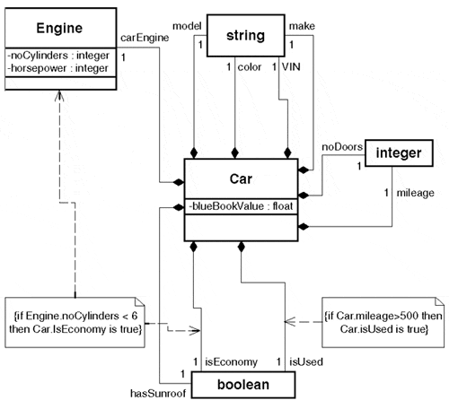
| Discussion | The attribute compartment of a UML class symbol serves as a useful place to list the inventory of the class's attributes, but it is rather limited when it comes to identifying and elaborating on particular attributes. A better place for a sophisticated description of attributes is physically external to the class using UML's powerful relationship descriptors such as constraints, multiplicity (only on the non-aggregate end for composites), qualified associations, ordering information, and improved room for note and constraint attachment. The "Notation Guide" section in the UML Specification specifically observes that "attributes are, in effect, composition relationships between a class and the classes of its attributes" (Rational Software Corporation 1999, 3-75). In other words, all attributes are really a particular instance of composition implemented by value. Composition also implies a constraint to single multiplicity on the aggregate side. Therefore, an attribute is actually the composition of a type with a 0 or 1 multiplicity on the source end. Figure 4.1 is a simple class diagram, showing a class that internally lists the attributes describing a car. Figure 4.1. Simple class diagram, showing attributes of describing a car. All attributes are shown in the compartment, including both primitive and class.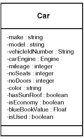 Applying this pattern, you can see that the resulting class diagram is more detailed and expressive (see Figure 4.2). By breaking the attributes out of the attribute compartment as compositions to classsymbols of the attribute type, you can more clearly identify the attribute identified with notes and/or engaged by constraints. Because it is the type of an attribute in the Car class, the Engine class was added to the diagram, which allows constraints to be attached that describe important conditional relationships between Engine and Car. Although having Engine and Car on the same diagram is likely to occur during initial modeling, it isn't unusual for class types to appear in attribute compartments when using classes from a class library or repository. The two constraints shown in Figure 4.2 also demonstrate how constraints can be connected directly to attributes instead of classes. The advantage of using this pattern is the capability to show attributes using the same notation that makes classes in a class diagram so visually compelling. An attribute shown this way gains the same range of expression that groups of collaborating classes have. This gives you improved flexibility and control over attribute definition and allows you to do the following:
|
Figure 4.2. Car class shown with attributes shown as compositions to attribute types.
4.2 Providing Focus
| Problem | Losing central item (class, use case) in diagram clutter. |
| Context | Any UML diagram containing many items. |
| Forces |
|
| Solution | Apply bold lines and fonts, or shaded areas to emphasize key details. Using colored elements is also becoming increasingly frequent. Depending on the diagram type, the target of emphasis may vary. (See Table 4.1 on next page.) |
| Resulting Context | A UML diagram in which attention is appropriately drawn to the key elements of the diagram. |
| discussion | Visual cues that highlight important pieces ofinformation in a standardized way help draw users' attention to important elements and emphasizecentral or key concepts in a diagram. The overall readability and clarity of a UML diagram can be improved by using standard highlighting mechanisms such as bold lines and text,shaded and color areas, and spatial emphasis techniques such as key element centering(see Table 4.1). |
| Diagram | Bold lines | Fonts | Shading/Color | Spatial emphasis |
|---|---|---|---|---|
| Class | Class box, relationships | Class names, key attributes and operations, role names, stereotypes | Class box or specific compartment, packages | Put central item in middle of diagram |
| Sequence | Object box, key message traces (especially the entire path through key sequence) | Object names/types, operation descriptions | Object box, activation boxes | Size object boxes, depending on granularity of object |
| Collaboration | Object box | Object names/types, operation descriptions | Object box | Put central item in middle of diagram |
| State | State box, transitions | State name, actions, events, guard text | State box | |
| Activity | Activity box | Activity name, condition text, swimlane text | Activity box, start and end points, swimlanes | Put key activities in swim lane on leftmost side |
| Component | Component symbol, process symbol, dependencies, subsystem packages, interface symbols | Component name, stereotypes, interface names | Component box, process box, subsystems boxes | |
| Deployment | Node symbol, | Node name, stereotypes | Node symbol | Group nodes to show areas communication of responsibility or com relationship mon physical locations |
4.3 Explicit Elision
| Problem | A diagram becomes too cluttered with irrelevant attributes, properties, and relationships. |
| Context | Any UML diagram that provides focus. |
| Forces |
|
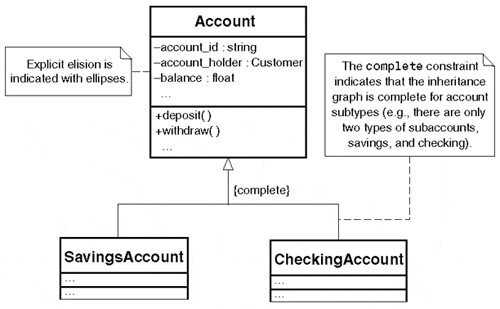
| Solution | Intentionally omit attributes, operations, relationships, classes, components, or any UML element in a diagram when the element is not central to the design idea being presented. Where possible, indicate explicitly when any list of items is not complete. In the UML, a model element does not have to be present in a diagram that graphically expresses a view of the model. This is called elision. Omitted elements are said to be elided. Elision of an element in a diagram has no impact on its status in the model itself. For example, classescan be shown without their attribute and operation compartments without implying that thoseattributes and operations don't exist. However, elision by itself can make understanding UML models tricky when you can't really be sure that any given diagram is displaying the entire picture. For that reason, use explicit elision. That is, clearly state that model elements have been omitted. For example, use an ellipsis (" . . .") to indicate when any list of items is not complete, as in an attribute compartment where only a subset of the attributes is presented. A UML complete constraint can also be attached to a group of elements (such as derived classes) to indicate that the classes shown (both in the model and diagram) comprise the total elements in the list. Finally, a note can be used where the ellipsis or complete constraint are inappropriate to indicate when the elements shown are complete or partial listings. A different aspect of explicit elision is detail appears once. When you model something, put the detail in only one place, and then reference it in others. For example, if you chunk your static model into several diagrams, the complete class detail appears in only one diagram and is elided in the others. Otherwise, you end up with a maintenance headache, and your diagrams lack focus. This becomes a real challenge when you capturedifferent types of information in different tools, such as business rules in one tool (for example, a rules engine or other tool that can check consistency) and use cases referencing them in another (for example, a text editor). In this example, you elide the business rule references in the use cases by numbering them and/or giving them descriptive names to key them into the rules engine. |
| Resulting Context | A UML diagram that contains only the elements that are absolutely essential to accurately present the concept behind the view. |
| Discussion | As a rule, keep in mind that the number of assumptions that have to be made about the presence and absence of model elements in a diagram will raise the value of the content in a UML diagram. Deciding what to include and what to exclude in a given diagram is always difficult, but the following criteria can be used: Include:
Exclude:
|
Figure 4.3. Explicit elision makes the presence and absence of model elements clear to the diagram user.
4.4 Tree Routing
| Problem | How to connect many similar UML relationships to a class in an efficient way. |
| Context | Modeling complex relationships of the same type in a static diagram. |
| Forces |
|
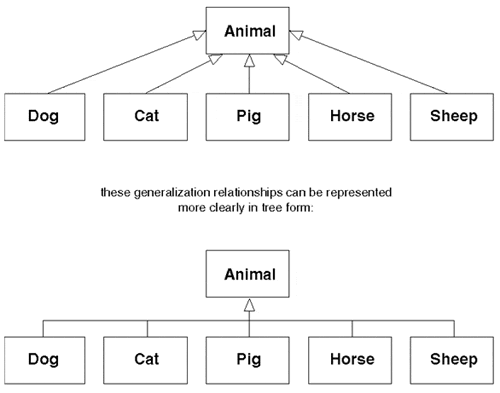
| Solution | Roll UML relationships of the same type pointing to a class up into a single line (that is, establish a single point of contact with the target class). This is called tree routing. It is so named because the relationship lines branch out from the class in a central trunk line. It is especially appropriate for displaying aggregation and generalization relationships. |
| Resulting Context | Controlled diagram clutter by means of space-efficient line routing. |
| Discussion | With the exception of time-sequenced graphs, a UML diagram's layout generally has little or no semantic value. However, a lot of the communication value inherent in a UML diagram is still due to the layout skill of the modeler. This isparticularly true when a large number of relationships must be drawn between the elements of a UML diagram. Tree routing is the most efficient and cleanest-looking relationship line routing strategy that can be used in static diagrams. Not only does tree routing reduce the overall amount of diagramspace and line complexity used, but it also provides a tremendous reduction in anchor space on the target class, especially in large inheritance hierarchies and complex aggregates (see Figure 4.4). Tree routing has some basic requirements that must be met before it can be used, but they are easy to keep in mind:
|
Figure 4.4. The tree routing approach (bottom) often results in cleaner diagrams,especially as the number of relationships that must be connected to the class grows.
4.5 Tombstone Packages
| Problem | The monotonous, minimally informative top-level package list, especially in models that are tool-generated; in particular, a row and column list of packages that is without any explanation of the relationships between them. Such listings (which look like rows of tombstones) often lack any explanation of (inter)dependencies, generalization, and traceability between packages, yet this is often where it's particularly needed at the highest level of the model. |
| Context | At the system level (global model scope) or any package level diagram, where a non-trivial model will have the list of packages into which model elements are grouped. |
| Forces |
|
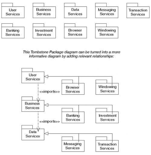
| Solution | Create meaningful package diagrams that always have the relationships between them clearly stated. Be especially careful to model dependencies between packages. Layer the packages into tiers that reflect the architectural decisions made in the design of the system. This may be a three- or four-tier structure, or something altogether different, depending on the domain of the model (see Figure 4.5). For models that separate specification andimplementations, be sure to always placerealization lines between the specification andthe implementation. Packages can also inherit from each other. When this occurs, make sure the generalization relationship is always clearly visible in diagrams where the packages and their subpackages appear. |
| Resulting Context | A diagram in which the packages are listed as well as the relationships between them, especially dependencies and generalizations. Trace relationships should be used in diagrams depicting the antecedent dependencies between packages. |
| Discussion | Too often, especially in modeling-tool environments, automatically generated lists of packages are dumped in package class diagrams, and pages of unhelpful grids of packages are created. Typically, however, packages will have important relationships between them that should be documented. Package diagrams are important for conveying the relationships between the groups of elements in your models The savvy modeler is wise to avoid having tools draw diagrams that aren't then carefully examined and modified to suit the architecture's style, form,and usage rules. |
Figure 4.5. These two diagrams show the vast difference between Tombstone Packages and a properly refactored package diagram.
4.6 Inheritance Goes Up
| Problem | How to diagram the UML generalization relationship in an industry-wide, accepted way. |
| Context | UML use case and class diagrams that contain generalization relationships. |
| Forces |
|
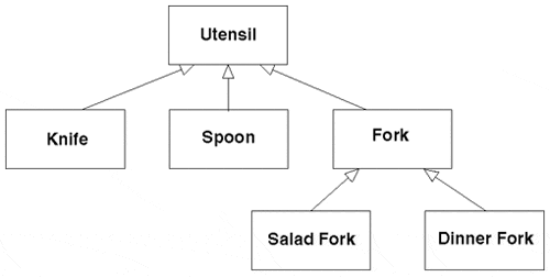
| Solution | The majority of all UML diagrams depict the generalization relationship with the more general element on top. Although exceptions can be found, the generalization arrow is expected to point toward the top of the page. So, wherever possible within the balance of forces, place the more general element above the more specificelements, and draw the generalization arrow between them. Less frequently, the generalization relationship may be seen as a horizontal line, especially when depicted as realization. Use it sparingly, however, to increase stylistic consistency. Refrain from placing the more general element under the more specific element. |
| Resulting Context | A UML diagram that shows generalization with the arrow pointing above the horizontal line toward the more general element (see Figure 4.6). |
| discussion |
Although conformity is not automatically a good thing, the upright generalization convention is one of the older ones in object-oriented modeling, and the tradition has carried through to UML in which the majority of generalization relationships are shown this way. Although the semantics of a diagram are unchanged by the application of this pattern, overall readability and usability are enhanced by its use. |
Figure 4.6. The canonical diagrammatic form for the UML generalization relationship.
4.7 Rotated Text
| Problem | Large text labels, especially those attached to vertical and diagonal UML relationships paths, are cumbersome and waste space by sticking out horizontally. |
| Context | Any UML diagram element that requires a text label. |
| Forces |
|
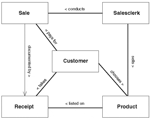
| Solution | Rotate text 45 or 90 degrees so that it is aligned along the relationship line or model element near which space must be conserved. Be sure to orient all vertical text labels in the diagram in the same direction. Diagonal text labels can follow the diagonal line unless they line is very steep. |
| Resulting Context | A UML diagram in which the text labels areoriented in the same direction as the long side of the model element to which they are attached (see Figure 4.7). |
| discussion | A vertical line with a horizontal text label,especially a long one, creates a layout problem because the label will spill over in either direction, waste valuable diagram space, and appear visually ungainly. Although many modeling tools may not provide this option, rotating the text 90 degrees solves the layout problem with a slight risk of making the diagram a bit harder to read. The result, however, is simpler and cleaner than having wide text labels protruding from vertical relationship lines and model elements. |
Figure 4.7. Sideways text can help modelers use space far more efficiently. Note that the text label on the association between Sale and Receipt is far more compact than a horizontal label would allow.
4.8 Dual Associations
| Problem | Association relationships can become visually and semantically overloaded with adornments such as multiplicity, role names, association names, reading direction arrows, association class attachments, and so on. |
| Context | A complex bi-directional association depicted in a UML class diagram. |
| Forces |
|
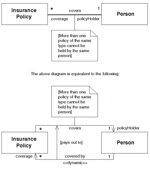
| Solution | Split the association into two one-way associations. Make sure that the multiplicities match.Use the duplicate space provided by the additional association line to attach an extra reading direction text and arrow, connect an additional association class, add constraints and stereotypes, and connect the two association with a shared association class. |
| Resulting Context | Two one-way association relationships in the place of a single bi-directional association(see Figure 4.8). |
| discussion | As long as some care is taken, two one-way associations can be equivalent to a single bi-directional association but with twice the path and adornment space. This provides extra room for the modeler to attach necessary adornments that would not be easy or even possible when using a single association. The semantics of the two one-way associations can also express a richer set of meanings than a single relationship, such as allowing a constraint to be attached in one direction only. Although care must be exercised to ensure that the resulting associations are not confusing to the reader, the dual association is a powerful stylistic technique that can express important details that add otherwise difficult to express semantics to a model. |
Figure 4.8. The diagram on the bottom shows how the Dual Association pattern can be used to supply extra adornment space and semantic control over the association between Insurance Policy and Person.
4.9 Billboard Packages
| Problem | Providing context for use cases and classes in a UML diagram, especially as they relate to development phase, perspective, and view. |
| Context | UML use case and class diagrams in general. |
| Forces |
|
| Solution | Physically display the use cases and classes within the packages they come from, especially when the use cases and classes are imported. Be sure to display the full package names and other context information such as package stereotypes. Always model relationships keyed to the diagram's purpose. |
| Resulting Context | UML use case and class diagrams in which context is provided by the display packages that wrap external (to the native package) use cases and classes. |
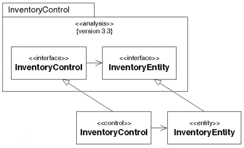
| Discussion | Packages are a management and grouping mechanism that provides a powerful way to structure models. Packages can be used to create collections of related model elements by using any criteria the modeler requires, such as development phase, abstraction, view, model type, and so on. Consequently, packages describe important context information about the model elements that they contain by virtue of the semantics that have been applied to the package (usually through stereotypes such as <<use case model>, <<analysis>, and so on). One concern that Billboard Packages help with is traceability showing how model elements are propagated through the various stages of development and associated models. However, traceability is allowed only between model elements in different packages; this is where Billboard Packages are effective. By placing use cases and classes within elided package icons along with their stereotype, Billboard Packages can offer important context cues to the diagram user. This helps the user understand the element's relation to the diagram and even to the rest of the model (see Figure 4.9). Note that the presence of the Inventory Control Billboard Package supplies crucial context information, such as which version of the types are being realized. |
Figure 4.9. This class diagram shows how control and entity class can realize interfaces defined in an analysis model kept in a separate package.
4.10 Text Workarounds
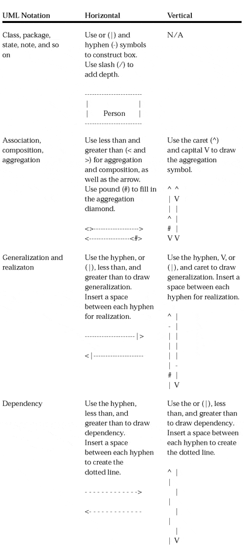
| Problem | Many of the notations in the UML are not directly supported by all the environments in which diagrams have to be viewed. Nevertheless, for these media (such as e-mail, simple drawing tools, and HTML, to name a few) the diagrams must still be rendered in a way that is understandable without significant interpretation. |
| Context | Viewing UML diagrams in environments that do not directly support UML's notational constructs, including lines, rectangles, diamonds, arrows, guillemets, and so on. |
| Forces |
|
| Solution | Use textual substitutions for UML model elements wherever possible (see Table 4.2). Adhere to symbols available in ASCII; and construct the boxes, lines, arrows, and other model elements using collections of ASCII characters. Use a monospace font if available, try to control the word wrapping in the hosting environment by using carriage returns, and use smaller fonts to keep as much of the diagram onscreen as possible. |
|
| |
| Resulting Context | A usable UML diagram in an environment that does not support UML graphics directly. |
4.11 Seven Plus or Minus Two
| Problem | How to make diagrams that can be grasped easily. |
| Context | Building diagrams that are themselves part of an overall model. In this case, you are specifically concerned with software models, but the pattern could apply to any type of potentially complex model using standardized modeling elements and syntax. |
| Forces |
|
| Solution | Limit the number of elements in any given diagram to the magic number of seven, give ortake two elements. These elements should be logically related; the diagram structure should express a sensible pattern connecting the diagram elements. |
| Resulting Context | Diagrams that are easy to understand at a glance and able to be organized in a logical fashion into more complex models. |
| discussion | Humans have limited cognitive resources. That is, they can attend to only so many things and perform so many activities at one time. Too many elements in a diagram can be confusing and are hard to retain in short-term memory all at once. This pattern provides a simple way of ensuring that the number of elements is reasonable for most people. The related pattern called Digestible Chunks (see Chapter 5, "Patterns of Substance" ) explains how and why the process of decomposing a model into logical diagrams works. |
EAN: 2147483647
Pages: 100
