Review of Previous IEEE 802.11 Security Mechanisms
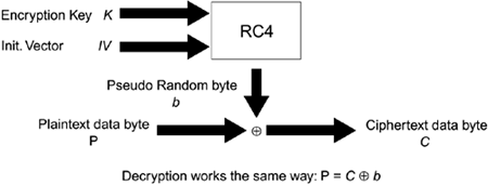
| The original (1999) version of the IEEE 802.11 specification defines several security mechanisms. The first is the wired equivalent privacy (WEP) protocol, which was designed to provide users with the same level of confidentiality protection as that of a wired network. The standard also includes a shared key authentication mechanism and integrity protection against inadvertent errors. While access control is not specifically addressed in the standard, most vendors have implemented an access control list mechanism based on MAC addresses. ConfidentialityIn the 1999 version of the standard, confidentiality is implemented through the WEP protocol, which uses RC4 for encryption (Menezes et al, 1996; Schneier, 1996). RC4 is a proprietary stream cipher designed by Ron Rivest in 1987. The algorithm was reverse-engineered and made public anonymously in 1994. While the algorithm has received a great deal of public attention, RSA Labs still claims the algorithm is a trade secret. RC4 and WEPRC4 is a remarkably simple cipher. As a result, the performance of the algorithm is high. It also makes describing the algorithm easy. There are two major phases in RC4. The first phase is the key setup algorithm (KSA), which establishes a 256-byte array with a permutation of the numbers 0 255. The permutation in the array, or S-box, is established by first initializing the array with the numbers 0 255 in order. The elements in the S-box are then permuted through the following process. First, a second 256-byte array, or K-box, is filled with the key that repeats as needed to fill the array. Next, the bytes in the S-box are swapped according to the pseudocode in Equation 15-1. Equation 15-1 RC4 Key Schedule Algorithmi = j = 0; For i = 0 to 255 do J = (j + Si + Ki) mod 256; Swap Si and Sj; End; The next phase in RC4 is the pseudorandom generation phase. In this phase, the algorithm in Equation 15-2 generates a pseudorandom byte R. Equation 15-2 RC4 Pseudorandom Generation Algorithmi = (i + 1) mod 256 j = (j + Si) mod 256 Swap Si and Sj K = (Si + Sj) mod 256 R = SK To produce n pseudorandom bytes, the algorithm executes Equation 15-2 n times. To encrypt plaintext, the stream of generated pseudorandom bytes is combined with the plaintext bytes using the XOR function as a combining function, as shown in Equation 15-3: Equation 15-3 RC4 EncryptionCi = Pi + Ri where Ci is the ith ciphertext byte, Pi is the ith plaintext byte, and Ri is the ith pseudorandom byte. The decryption process is just the inverse encryption shown in Equation 15-3 and is shown in Equation 15-4. Equation 15-4 RC4 DecryptionPi = Ci + Ri The equations shown in Equations 15-3 and 15-4 are a Vernam cipher (Vernam, 1926). The Vernam cipher, designed by Gilbert Vernam during World War I while working for AT&T, is the only completely secure encryption system provided that Ri is a true random byte. In this case, Equations 15-3 and 15-4 are known as a one-time pad. To be completely secure Ri must be truly random, and a random sequence must never be used more than once. Because the former Soviet Union made this serious mistake following World War II, the American National Security Agency was able to decrypt a number of one-time pad enciphered messages sent by Soviet agents in a project code named VENONA (U.S. NSA, 1999). RC4, however, is not a completely secure encryption system because it generates pseudorandom bytes, not truly random bytes. WEP uses RC4 along with an initialization vector (IV) to ensure that each message encrypts differently along with a 32-bit cyclic redundancy check to protect data integrity during the transmission of encrypted 802.11 packets. Initialization VectorWEP uses a 24-bit IV in an attempt to ensure that RC4's pseudorandom byte stream is not reused because reusing the same pseudorandom byte stream creates depth, which can make the attacker's job easier. The sender uses a unique key with every packet that is derived by appending the shared secret key, k, to the publicly known IV. This process is shown in Figure 15.1. Figure 15.1. RC4 as Used in WEP
Integrity Check ValueWEP uses a 32-bit cyclic redundancy check (CRC) as an integrity check value (ICV). The ICV detects any changes (malicious or inadvertent) in the transmitted message's underlying plaintext. Unfortunately, while a CRC easily detects most inadvertent changes, it does not provide integrity or message authenticity capabilities against malicious changes. Thus, an attacker can easily modify messages protected by a CRC. A CRC uses the mathematics of finite fields, more specifically, GF(2). Fortunately, the mechanics (not the mathematics) of how a CRC works are easily explained. A message M that is n + 1 bits long can be represented as an nth-degree polynomial, M(x). For instance, consider a message consisting of only the single ASCII letter "O," which is represented in binary as 01001111. The polynomial corresponding to this message is 07 + x6 + 05 + 04 + x3 + x2 + x + 1, or x6 + x3 + x2 + x + 1. For a CRC to work, both the sender and the recipient must agree upon a polynomial G(x) of degree m that will be used to calculate the CRC.[2] This polynomial will be used as a divisor for the message.
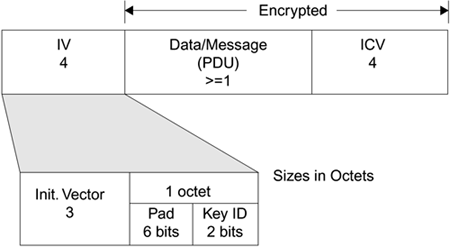
The WEP CRC polynomial is G(x) = x32 + x26 + x23 + x22 + x16 + x12 + x11 + x10 + x8 + x7 + x5 + x4 + x2 + x + 1, with m = 32 (IEEE, 1997). Transmitting an n + 1-bit message, M also transmits an additional m bits, for a total message length of n + m + 1 bits. We'll call the message and the additional m bits the polynomial P(x). The m + 1 bits added to the original message make P(x) divisible by G(x) with a remainder of 0. The m + 1 bits are determined by increasing the degree of M(x) by m, then by multiplying M(x) by xm to obtain M´(x), and then dividing M´(x) by G(x). The remainder, if any, is then subtracted from M´(x), resulting in P(x) the transmitted value of n + m + 1 bits. Verification of the CRC by the recipient involves a similar process. The recipient divides P(x) by G(x), and if the remainder is 0, the message does not contain unintentional errors. The key word here is unintentional because CRCs do not prevent the introduction of intentional errors when the attacker knows G(x).The attacker only needs to modify M(x) and calculate new m + 1 bits, just as the sender did. An example of how to calculate a CRC is provided in Appendix B. WEP Datagram FormatFigure 15.2 shows the WEP datagram format. The preamble of the datagram is a four-octet value that includes the 24-bit IV in plaintext, a 6-bit pad, and a 2-bit keyID value. Figure 15.2. WEP Datagram Format
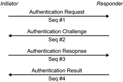
The WEP datagram format can be represented by C = RC4(IV, k) An important point to remember about WEP is that the plaintext and the pseudorandom bytes produced by RC4 are combined with a linear function, XOR. This fact causes significant problems for WEP that are discussed later in this chapter. Key ManagementThe 802.11 standard neither addresses link-layer key management nor does it provide recommendations for upper-layer key management. The standard, instead, relies only on manual key management, which is difficult to perform in a timely manner when the number of hosts is large. As a result, only a few major vendors initially implemented any form of key management or key agreement in their high-end products, and all of these products use upper-layer methods. Unfortunately, the vendors do not provide sufficient information to determine the level of assurance their products provide. Worse, in some cases, available details indicate that vendors' "solutions"' worsen the problem by using protocols with well-known vulnerabilities for example, an unauthenticated Diffie-Hellman key agreement. The 802.11 standard offers two methods for using WEP keys. The first provides a window of four keys. A station or access point (AP) can decrypt packets enciphered with any one of the four keys; transmission, however, is limited to one of the four manually entered keys the default key. The second method is called a key mappings table. In this method, each unique MAC address can have a separate key. According to the 802.11 specification, a key mappings table should have at least ten entries. The maximum size, however, is likely chip-set dependent. Having a separate key for each user makes the cryptographic attacks found by others slightly more difficult because the traffic per key will be reduced, but enforcing a reasonable key period remains a problem as the keys can only be changed manually. Access ControlAccess control is a major component of any secure architecture. The previous 802.11 standard does not define any means for access control. As a result, most vendors implement access control lists using the client's MAC address as its identity, and one major vendor implements a proprietary access control using a shared secret. Each access point can limit network access to clients using a listed MAC address. If the client's address is not listed, access to the network is prevented. A major wireless vendor has defined Closed Network, a proprietary access control mechanism. With this mechanism, a network manager can use either an open or a closed network. Anyone is permitted to join an open network, but only clients with knowledge of the network name, or SSID, can join a closed network. In essence, the network name acts as a shared secret. Unfortunately, because the SSID is sent over the air unencrypted, it is not a well-protected secret. Integrity and AuthenticationThe current IEEE 802.11 standard does not have a robust mechanism designed specifically for integrity purposes. Some claim that the 32-bit CRC ICV function provides integrity; but, as we have seen, this is not the case in practice. The 1999 specification has only two forms of standardized authentication in 802.11 open system and shared-key authentication. Open System AuthenticationOpen system authentication is the default authentication protocol for 802.11. As the name implies, this method authenticates anyone who requests it; in essence, it provides a NULL authentication process. This method was likely included in the standard to permit the use of a single-state machine that supports authenticated and unauthenticated operation. Shared-Key AuthenticationShared-key authentication uses a standard challenge and response along with a shared secret key to provide authentication. The station wishing to authenticate, the initiator, sends an authentication request management frame indicating that it wants to use shared-key authentication. The recipient of the authentication request, the responder, responds by sending an authentication management frame containing 128 octets of challenge text to the initiator. The responder generates the challenge text by using the WEP pseudorandom number generator (PRNG) with the shared secret and a random IV. The IV is always sent in the clear as part of a WEP-protected frame. Once the initiator receives the management frame from the responder, it copies the contents of the challenge text into a new management frame body and then encrypts it with WEP, using the shared secret along with a new IV selected by the initiator. The initiator then sends the encrypted management frame to the responder. The responder decrypts the received frame and verifies that the 32-bit CRC integrity check value (ICV) is valid and that the challenge text matches that sent in the first message. The entire process is shown in Figure 15.3. Figure 15.3. Authentication Sequence
|
EAN: 2147483647
Pages: 151


 <M, CRC(M)>