Using the ShapeSheet Window
3 4
In other parts of this book, the ShapeSheet window has been introduced as a way to complete certain tasks that can't be done on the drawing page. But what exactly is the ShapeSheet window? "Shapes are ShapeSheets, and ShapeSheets are shapes," said one of the authors of the ShapeSheet interface, who regards the window as simply another view of a shape. The graphical view is the shape you see on the drawing page. The ShapeSheet view looks beneath the surface to describe the geometry, formatting, and other settings that make up a shape, as Figure 25-1 shows. A section describes a particular behavior of a shape. For example, the Shape Transform section describes a shape's general position.
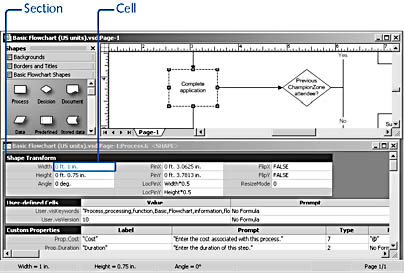
Figure 25-1. The ShapeSheet window contains cells and formulas that control the geometry, formatting, and other characteristics of shapes.
The ShapeSheet window is in essence a spreadsheet of rows and columns with a macro language not unlike that of other Office programs. When you select a cell in a section, the cell's contents appear on the formula bar at the top of the window. Cells contain the instructions that Visio uses to create a shape. Moreover, you can edit these instructions to control a shape's appearance and behavior.
Tip - Add a ShapeSheet Command to the Shortcut Menu
For easy access to the ShapeSheet window, you can add a shortcut command that appears when you right-click a shape. Choose Tools, Options. On the Advanced tab, select Run In Developer Mode, and then click OK. This command also adds the Add-Ons command to the Tools menu.
InsideOut
When you choose Window, Show ShapeSheet, Visio displays the ShapeSheet properties for the currently selected object in a new window. If you select a second object on the drawing page and repeat the command, the new object's properties are displayed in a new window. However, you can display a new object's properties in the same ShapeSheet window. Choose Tools, Options. On the General tab, select the Open Each ShapeSheet In The Same Window check box, and then click OK.
Visio can represent any of the following objects in the ShapeSheet window: shape, guide, guide point, object from another application, master shape, group, each member of the group, or drawing page. Table 25-1 describes how to display the ShapeSheet window for each type of object.
Table 25-1. Techniques for Opening the ShapeSheet Window for an Object
| Object | Procedure |
|---|---|
Shape, guide, guide point, or object from another application | Select the object, and then choose Window, Show ShapeSheet. |
Group | Select the group, and then choose Window, Show ShapeSheet. |
Shape in a group | Subselect the shape, and then choose Window, Show ShapeSheet. |
Master shape | Open a stencil for editing. Right-click a master, and then choose Edit Master. Select the master shape, and then choose Window, Show ShapeSheet. |
Page | Make sure nothing is selected, and then choose Window, Show ShapeSheet. |
Viewing ShapeSheet Sections
Depending on the type of object you select, the ShapeSheet window will include a subset of the 34 possible sections. Most objects include a Shape Transform section, but, for example, only 1-D shapes include a 1-D Endpoints section. Visio adds the section it requires to build an object; other sections appear only if you explicitly add them. For example, the Scratch section, which programmers can use for their own formulas, doesn't appear in the ShapeSheet window unless you add it. You can also show and hide sections by choosing the Sections command on the View menu, as Figure 25-2 shows.
Note
The Sections command is available only when the ShapeSheet window is open.
If a section doesn't appear, you might be able to add it. Some sections don't apply to the selected object, but others provide you with additional options. For example, you can add the Actions section to the ShapeSheet window to add commands (actions) to an object's shortcut menu.
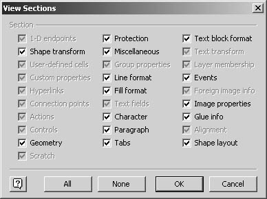
Figure 25-2. The ShapeSheet window for the selected shape displays all the available sections, as the check marks in the View Sections dialog box indicate. Options that appear dimmed represent nonexistent sections, some of which are irrelevant for the object.
Follow these steps to add a section:
- With the ShapeSheet window active, choose Insert, Section.
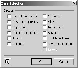
- Select the sections you want to add, and then click OK.
Tip
You can collapse ShapeSheet sections so that you can see more sections at once by clicking a section name.
Touring the ShapeSheet Sections
Given the number of different ShapeSheet sections, it's not practical to describe them all here. However, Table 25-2 describes a subset of sections that are useful to know about, particularly if you want to gain a deeper understanding of shape behavior. When you tour the ShapeSheet window, remember that most cells have a one-to-one correspondence with an option that you've probably seen elsewhere. For example, most of the Shape Transform cells have counterparts in the fields of the Size & Position window, and cells in the Line Format section reflect the options in the Line dialog box.
Tip
To display help for any ShapeSheet cell, select a cell, and then press F1. Microsoft Visio Developer Help opens and displays the topic for that cell.
Table 25-2. Common ShapeSheet Sections
| Section | Description |
|---|---|
1-D Endpoints | Cells in this section describe the exact position of each endpoint on a 1-D shape. |
Custom Properties | This section stores the labels and values of a shape's custom properties if it has any. You can add properties in the ShapeSheet window by choosing Shape, Custom Properties. |
Fill Format | Cells in this section reflect the settings of the Fill command on the Format menu. |
Geometry | This section defines the exact position of each shape vertex as an x- and y-coordinate and shows the type of lines and segments that make up the shape. A shape with multiple paths will include a Geometry section for each path. |
Group Properties | In a group, the settings specified by the Behavior command on the Format menu are stored in this section. |
Line Format | Cells in this section reflect the line formatting and line end settings specified with the Line command on the Format menu. |
Miscellaneous | This section contains an assortment of shape settings that control shape selection and visibility, most of which can be set with the Behavior command on the Format menu. |
Paragraph | Cells in this section reflect the paragraph formatting settings specified with the Paragraph command on the Format menu. |
Protection | This section reflects the protection lock settings specified with the Protection command on the Format menu. However, this section includes a few locks that the Protection command doesn't, such as LockFormat, LockTextEdit, and LockGroup. |
Shape Transform | This section stores the shape's size, position on the page, and orientation and reflects the settings shown in the Size & Position window. |
Text Transform | Like the Shape Transform section, this section contains size and position information—but only for the shape's text block. |
User-Defined Cells | Many Visio shapes include this section, which doesn't correspond to any commands on the drawing page. Instead, it provides a work area for any type of formula. Microsoft shape designers store keyword information used by the Find Shapes command in this section. |
EAN: 2147483647
Pages: 211
- Key #4: Base Decisions on Data and Facts
- Beyond the Basics: The Five Laws of Lean Six Sigma
- Making Improvements That Last: An Illustrated Guide to DMAIC and the Lean Six Sigma Toolkit
- The Experience of Making Improvements: What Its Like to Work on Lean Six Sigma Projects
- Six Things Managers Must Do: How to Support Lean Six Sigma