ONS 15454 MSTP DWDM Design Considerations
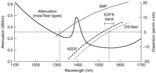
| In general, DWDM designers and planners must be cognizant of several factors that influence system topology and transmissions capability. Among them are physical limitations, such as structure locations, and fiber plant type. Additionally, the system bandwidth requirements and scale should be taken into account, along with the DWDM equipment limitations such as amplifier noise limitations (OSNR) and receiver minimum power levels. For existing DWDM deployments, physical structure locations are usually already predetermined for amplifier/regenerator locations. For example, existing DWDM systems may use 60 km amplifier spacing rules; thus, because outside plant enclosures and power are already present at these locations, it is prudent for the DWDM designer to engineer the new system within the present amplifier spacing rules. The drawback associated with using existing structures and spacing is that it might be economically inadvisable or systematically impossible to design the new DWDM system within old physical constraints. In addition to physical structure requirements, when providing DWDM over existing fiber infrastructure, the design is usually constrained by the transmission characteristics of the existing optical fiber. Essentially, three types of fiber are used today: standard, single-mode fiber; nonzero, dispersion-shifted fiber (NZDF); and dispersion-shifted fiber (DS-fiber). Figure 10-1 details the typical attenuation and chromatic dispersion profiles for each fiber type. Figure 10-1. Optical Fiber Performance Profile From an attenuation standpoint, DWDM C-band and L-band operation occurs in the lowest optical loss region at 0.21 to 0.25 dB/km. The major transmissions difference among the fiber types revolves around their chromatic dispersion characteristics. As mentioned in Chapter 9, "Using the ONS 15454 Platform to Support DWDM Transport: MSTP," chromatic dispersion causes an optical signal to spread into adjacent bit periods, which can cause bit errors at optical receivers. Low-cost transmitter sources, which typically have wide signal spectral widths, exhibit more sensitivity to this factor over distance and time than higher-cost transmitters, which typically are constructed with tighter signal spectral widths. Figure 10-2 illustrates this phenomenon. Figure 10-2. Wavelength Signal Broadening Caused by Chromatic Dispersion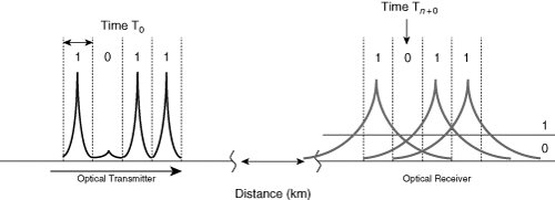 The DS-fiber mitigates this issue by shifting the zero-dispersion parameter from the 1310 nm region to the 1550 nm region. This facilitates long-distance, high-bit-rate transmission for a single wavelength at 1550 nm because only optical attenuation is a signal-impairment factor. However, the zero-dispersion property of DS-fiber causes many transmission abnormalities for high-powered, multiplexed wavelengths in the 1550 nm region, such as four-wave mixing (FWM), which makes it unsuitable for DWDM. Certain fiber anomalies, such as FWM and channel cross-talk, are offset by the chromatic dispersion effect. However, if the signal spreads too fast, dispersion compensation must be used to compress the wavelength spectrum to near its original form. Therefore, the right balance of optical power, signal spectral width, and chromatic dispersion is necessary for optimal DWDM distance extension. For single-mode fiber (SMF), wavelength spreading occurs at an average rate of 17 picoseconds (ps)/nm-km; for NZDF, the typical chromatic dispersion rate is around 4.4 ps/nm-km. It should be noted that the tolerance of chromatic dispersion decreases as the transmission's bit rate increases. As detailed in the following formula, each time-division multiplexing (TDM) increase in bandwidth results in a [1/16] reduction in transmissions distance.
Where:
Thus, to increase channel capacity from 2.5 Gbps to 10 Gbps (a fourfold increase), chromatic dispersion tolerance decreases by a factor of 16. Many other fiber-transmissions factors must be considered as well. The amount of polarization mode dispersion (PMD) in fiber can be a relevant factor in the maximum bit rate that can be transmitted. The PMD effect causes light signals to travel in two orthogonal modes; as a result, a portion of the signal pulse travels on a fast axis, and a portion travels on a slow axis. The downstream optical receiver is tasked with reconstructing both pulse axes into a single bit stream. Optical-fiber PMD can be caused by a number of elements, including glitches in the fiber-manufacturing process or mishandling of fiber during cable manufacturing or installation. The effect of other fiber nonlinearities, such as stimulated brillion scattering, stimulated raman scattering, cross-phase modulation, and self-phase modulation also must be taken into account when designing DWDM systems; however, these effects can be controlled with proper equipment design. Amplified systems present their own complexities in terms of optical signal-to-noise ratio (OSNR) and channel gain tilt. For example, when engineering each amplified span, the DWDM engineer must compute the OSNR between each span to ensure that the signal level is within receiver specifications for each amplifier in use. The following formula is used for OSNR measurement for a multistage amplifier: Where:
As you can see, manually computing the effects of each fiber transmission effect for each span/wavelength set can be a cumbersome task. For this reason, the ONS 15454 MSTP is broken into a set of design rules for each topology type. The design rules take into account the limitations of each optical component used within the system so that the DWDM engineer need only compute the optical fiber limitations, which vary from span to span. In the next sections, you examine a subset of the design rules associated with each of the topologies detailed in Chapter 9. |
EAN: 2147483647
Pages: 140