| The ONS 15454 Shelf Assembly is a 17-slot chassis with an integrated fan tray, rear electrical terminations, and front optical, Ethernet, and management connections. Slots 16 and 1217 are used for traffic interface cards; Slots 711 are reserved for common control cards. Slots 16, on the left side as you face the front of the shelf, are considered Side A; Slots 1217 are considered Side B. This distinction is important for planning backplane interface types (for electrical card terminations), as well as protection group planning. These issues are covered later in this chapter. The bandwidth capacity of each of the 12 traffic slots varies from 622 Mbps to 10 Gbps, depending upon the type of cross-connect card used. See the section titled "Cross-Connect Cards" later in this chapter for a discussion of the various types available. Table 6-1 summarizes the card slot functions and bandwidth capacities for the ONS 15454 shelf assembly. Table 6-1. ONS 15454 Shelf Assembly Slot Functions and Bandwidth CapacitiesSlot Number | Shelf Side | Slot Use | Slot Bandwidth (XCVT System) | Slot Bandwidth (XC10G or XC-VXC-10G System) |
|---|
1 | A | Multispeed high-density slot | 622 Mbps/STS-12 | 2.5 Gbps/STS-48 | 2 | A | Multispeed high-density slot | 622 Mbps/STS-12 | 2.5 Gbps/STS-48 | 3 | A | Multispeed high-density slot; N-protection slot for 1:N protection groups | 622 Mbps/STS-12 | 2.5 Gbps/STS-48 | 4 | A | Multispeed slot | 622 Mbps/STS-12 | 2.5 Gbps/STS-48 | 5 | A | High-speed slot | 2.5 Gbps/STS-48 | 10 Gbps/STS-192 | 6 | A | High-speed slot | 2.5 Gbps/STS-48 | 10 Gbps/STS-192 | 7 | | TCC Slot | | | 8 | | XC Slot | | | 9 | | AIC Slot | | | 10 | | XC Slot | | | 11 | | TCC Slot | | | 12 | B | High-speed slot | 2.5 Gbps/STS-48 | 10 Gbps/STS-192 | 13 | B | High-speed slot | 2.5 Gbps/STS-48 | 10 Gbps/STS-192 | 14 | B | Multispeed slot | 622 Mbps/STS-12 | 2.5 Gbps/STS-48 | 15 | B | Multispeed high-density slot; N-protection slot for 1:N protection groups | 622 Mbps/STS-12 | 2.5 Gbps/STS-48 | 16 | B | Multispeed high-density slot | 622 Mbps/STS-12 | 2.5 Gbps/STS-48 | 17 | B | Multispeed high-density slot | 622 Mbps/STS-12 | 2.5 Gbps/STS-48 |
ONS 15454 Shelf Assembly Backplane Interfaces Backplane interfaces of the ONS 15454 chassis can be divided into four general areas: Power terminal area Alarm and chassis ground area Side A Electrical Interface Assembly Side B Electrical Interface Assembly
Figure 6-1 shows a diagram that identifies the location of each of these areas as you face the rear of the shelf assembly. Electrical Interface Assemblies (EIAs) are required for terminating electrical traffic signals, such as DS1s and DS3s, on the shelf. EIAs are covered in the next section. Figure 6-1. ONS 15454 Backplane Interfaces 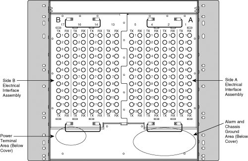
The power terminal area consists of four power terminal screws on the lower-left side. The RET1/BAT1 terminals are for the A power connection; the RET2/BAT2 terminals are for the B connection. These connections are redundant; either can power the entire shelf. The A and B designations do not refer to the A and B sides of the shelf. The alarm and chassis ground area is located in the rear of the chassis on the lower right side. It has the following terminations: Frame ground terminals Two terminals with kepnuts are provided for ground-wire lug connection. This connection ensures that the shelf assembly is at the same electrical potential with the office ground. BITS (Building Integrated Timing Supply) This consists of four wire-wrap pin pairs for connection to a BITS or for wiring out to external equipment when the BITS-Out feature is used to supply timing from the ONS 15454. LAN (Local-area network) A LAN connects the MSPP node to a management workstation or network. It consists of four wire-wrap pin pairs; typically, two pairs are used. Environmental alarms Sixteen wire-wrap pin pairs are provided for external alarms and controls. The Alarm Interface Controller card, covered later in this chapter, is required to use these connections. ACO Alarm cutoff, a wire-wrap pin pair that is used to deactivate the audible alarms caused by the contact closures on the shelf backplane. This operation is described in the "Timing, Communications, and Control Cards" section, later in this chapter. Modem Four pairs of wire-wrap pins are provided for connecting the ONS 15454 to a modem for remote management. Craft Two wire-wrap pin pairs are provided for a TL1 craft-management connection. VT100 emulation software is used to communicate with the system by way of this connection. Local alarms Eight wire-wrap pin pairs are used for Critical, Major, Minor, and Remote audible and visual alarms.
|