Section 1: Bridging and Switching (18 Points)


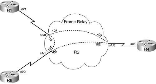
Section 1.1: Frame Relay Configuration (5 Points)

  • Configure the Frame Relay portion of the network as shown in Figure 3-11 and ensure that DLCIs 110 and 104 between R1 and R6 are not used. Do not configure any subinterfaces, nor rely on inverse ARP, nor use the command broadcast in your configuration. Assume a CIR of 128 kbps per PVC for IGP reference.

    Figure 3-11. Frame Relay Diagram


  • Configure the MTU on R1 and R6 to be 950 and leave the MTU on R4 as default.

Section 1.2: 3550 LAN Switch Configuration (10 Points)

  • Configure VLAN numbers, VLAN names, and port assignment as per the topology diagram.

  • The switch should be configured to log all debug information locally in a method so that it will not be lost in the event of a reset, it should also contain a timestamp.

  • Configure your switch not to allow R1 to Telnet into R6. Use VLAN2 addresses for your configuration. Your solution should be applied to the whole VLAN as opposed to individual ports.

  • Do not allow all ports on VLAN3 to multicast above 3 Mbps.

  • Ensure the switch is reachable via the IP address of 10.80.80.8/24.

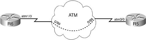
Section 1.3: ATM Configuration (3 Points)

  • Configure the ATM PVCs as shown in Figure 3-12. Use point-to-point subinterfaces and use the new format PVC vpi/vci when configuring the PVCs. Ensure that the ATM subinterfaces contain purely Layer 2 information, configure virtual Layer 3 addresses elsewhere for the ATM connectivity, and make this connectivity as secure as possible. This configuration does not require any form of bridging.

    Figure 3-12. ATM Diagram


CCIE Routing and Switching Practice Labs
ISBN: 1587051478
EAN: 2147483647
Year: 2006
Pages: 268

flylib.com © 2008-2017.
If you may any questions please contact us: flylib@qtcs.net