Repeaters and Bridges
| The information presented so far may be distilled into a few brief statements:
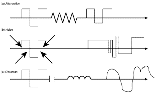
So here's this wonderful resource-sharing tool called a LAN. It's so wonderful, in fact, that everyone wants to be connected to it. And herein is the rub. As a LAN grows, new problems present themselves . The first problem is one of physical distance. Figure 1.4 shows that three factors can influence an electrical signal. These factors may decrease or eliminate any intelligence the signal represents:
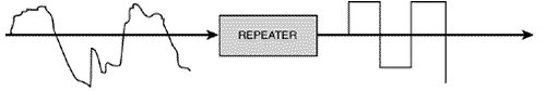
Figure 1.4. Attenuation, interference, and distortion prevent a signal from arriving in the same shape it was in when it left. Attenuation (a) is a function of the resistance of the wire. A certain amount of signal energy must be spent "pushing past" the resistance. Interference (b) is a function of outside influences ”noise ”which adds characteristics to the signal that should not be there. Distortion (c) is a function of the wire impeding different frequency components of the signal in different ways. As the distance the signal must travel down the wire increases , so do the degrading effects of these three factors. Photonic pulses traveling along an optical fiber are much less susceptible to interference but will still succumb to attenuation and distortion. Repeaters are added to the wire at certain intervals to alleviate the difficulties associated with excessive distance. A repeater is placed on the media some distance from the signal source but still near enough to be able to correctly interpret the signal (see Figure 1.5). It then repeats the signal by producing a new, clean copy of the old degraded signal. Hence, the name repeater . Figure 1.5. By placing a repeater in the link at a distance where the original signal can still be recognized, despite the effects of attenuation, interference, and distortion, a fresh signal can be generated and the length of the wire extended. A repeater may be thought of as part of the physical medium. It has no real intelligence, but merely regenerates a signal; a digital repeater is sometimes facetiously called a "bit spitter" for this reason. The second problem associated with growing LANs is congestion. Repeaters are added to extend the distance of the wire and to add devices; however, the fundamental reason for having a LAN is to share resources. When a too-large population tries to share limited resources, the rules of polite behavior begin to be violated and conflicts erupt. Among humans , poverty, crime, and warfare may result. On Ethernet networks, collisions deplete the available bandwidth. On Token Ring and FDDI networks, the token rotation time and timing jitter may become prohibitively high. Drawing boundaries between populations of LAN devices is a solution to overcrowding. This task is accomplished by the use of bridges . [6]
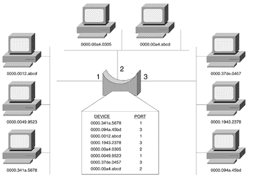
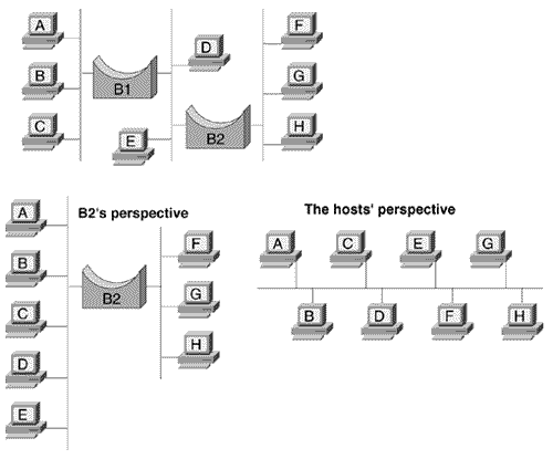
Figure 1.6 shows the most common type of bridge: a transparent bridge . It performs three simple functions: learning, forwarding, and filtering. It is transparent in that end stations have no knowledge of the bridge. Figure 1.6. The transparent bridge segments network devices into manageable populations. A bridging table tracks the members of each population and manages communication between the populations. The bridge learns by listening promiscuously on all its ports. That is, every time a station transmits a frame, the bridge examines the source identifier of the frame. It then records the identifier in a bridging table , along with the port on which it was heard . The bridge therefore learns which stations are out port 1, which are out port 2, and so on. In Figure 1.6, the bridge uses the information in its bridging table to forward frames when a member of one population ”say, a station out port 1 ”wants to send a frame to a member of another population: a station out port 2. A bridge that only learns and forwards would have no use. The real utility of a bridge is in the third function, filtering. Figure 1.6 shows that if a station out port 2 sends a frame to another station out port 2, the bridge will examine the frame. The bridge consults its bridging table and sees that the destination device is out the same port on which the frame was received and will not forward the frame. The frame is filtered. Bridges enable the addition of far more devices to a network than would be possible if all the devices were in a single population, contending for the same bandwidth. Filtering means that only frames that need to be forwarded to another population will be, and resources are conserved. Ethernet networks are divided into collision domains; Token Ring and FDDI networks are divided into multiple rings. Figure 1.7 illustrates two perspectives of a transparent bridge. It is transparent because the end stations have no knowledge of it. At the same time, a transparent bridge has no real knowledge of the topology of a network; the bridge only knows which identifiers are heard on each of its ports. Figure 1.7. Two perspectives of a transparent bridge. Some other types of bridges are source-route bridges, source-route/transparent bridges, translating bridges, and encapsulating bridges. For a complete discussion of bridge issues and functionality, see Perlman [1992], cited in the recommended reading list at the end of this chapter. The third problem posed by LAN growth is one of locality. Repeaters allow the distance of a LAN to be extended, but only within certain geographic limitations. Extending a LAN across the city or across the continent presents prohibitive costs in physical materials, engineering and construction, and legal issues such as rights-of-way. Such distances require the use of a wide-area network , or WAN. [7] Table 1.1 compares and contrasts LANs and WANs.
A fourth problem is one of scalability. Bridges allow a network to be segregated into smaller populations of stations; in this way station-to-station traffic is localized. Certain types of frames cannot be localized, though. Some applications require data to be broad cast ”that is, the data must be delivered to all stations on a network. Ethernet, Token Ring, and FDDI networks use a reserved destination identifier of all ones (0xffff.ffff.ffff) for broadcasting. Bridges must forward a broadcast frame out all ports to ensure that all stations receive a copy. As a bridged network becomes larger and larger, more and more stations will be originating broadcast traffic; soon, broadcasted frames cause the network to become congested again. Table 1.1. Fundamental differences between LANs and WANs.
Note Internetwork To manage broadcast traffic and other scaling challenges, another kind of boundary is necessary. Bridges allow the network to be divided into populations of stations, but a way to create populations of networks within a larger network is also needed. This network of networks is better known as an internetwork . The device that makes internetworks possible is a router. |