Section 13.1. OSPF Extensions for Multi-Topology Routing
13.1. OSPF Extensions for Multi-Topology RoutingAt the time of writing of this chapter, the first Internet Draft proposing Multi-Topology OSPF (MT-OSPF)[1] is only a few months old, and MT-OSPF has not yet seen general deployment. By the time you read this, the extensions are likely to be on vendors' development roadmaps, if not in production code.
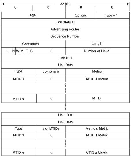
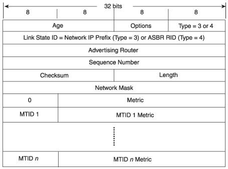
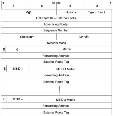
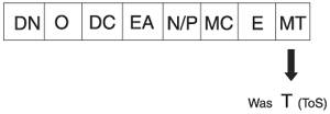
Although some extensions to OSPF have required new LSAs or even a new version of the protocol, MT-OSPF support is implemented simply by exploiting unused fields in modern OSPF LSAs. You might recall from Chapter 5 that OSPF was originally specified to support type-of-service (ToS) routing but that the option was never implemented commercially. Conveniently, the LSAs were designed to carry multiple ToS metrics. So, MT-OSPF redefines the ToS fields to carry MTIDs and their associated metrics. But before examining the changes to LSAs in Section 13.1.2, we will look at the OSPF procedure changes needed to support multiple topologies. 13.1.1. MT-OSPF ProceduresA Router (type 1) LSA originated by an MT-OSPF router lists, as usual, all OSPF links for that router and all the router's neighbors. The difference is that the LSA indicates for each link what topologies the link belongs to and a metric for the link that is specific to the topology. Type 3, 4, 5, and 7 LSAs are also modified to advertise not only prefixes (or in the case of type 4 LSAs, ASBRs) but what topologies the prefixes belong to and their metric in each topology. For each MTID listed by the LSAs in the link state database, a separate SPF calculation is run, and the results are recorded in a separate RIB. There is always a default topology, signified by a MTID of 0, which consists of all routers and links in the OSPF domain. Because OSPF routers that are not MT-aware ignore the ToS fields in the LSAs, and because the MTIDs and MT metrics appear in what were ToS fields, MT-OSPF is compatible with non-MT-OSPFassuming, of course, that all nondefault topologies consist of MT-OSPF routers. In other words, MT-unaware OSPF routers interpret MTID 0 as ToS 0, which is the normal OSPF procedure. The default topology is the foundation structure of the domain, and all other topologiessignified by MTIDs between 1 and 127are subsets of the default topology. Hellos are sent on all OSPF links regardless of the topologies the link belongs to, and the adjacencies between neighbors are not specific to any topology. An OSPF interface can only be configured to reside in a single area. Therefore, a link is in the same area regardless of whator how manytopologies use it. This implies that although a non-default topology might use only some of the routers and links of the default topology, it cannot have different area boundaries. The DR/BDR election process is independent of individual topologies, so a multi-access link has the same DR and BDR no matter what or how many different topologies it belongs to. Recall that Network (type 2) LSAs do not carry any link or metric information; they serve only to represent a broadcast network as a pseudonode on the SPF calculation. Therefore, type 2 LSAs need no modification to be used in MT-OSPF. The SPF calculations for each topology use the type 2 LSAs for any multi-access link included in the topology. Finally, if a link state changes for any topologywhether a metric change or a change in its availabilitythe routers attached to the link must flood a new type 1 LSA indicating the change, even if the state change affects only one topology and not all topologies to which the link belongs. Similarly, if a prefix or ASBR changes, the appropriate type 3, 4, 5, or 7 LSA must be flooded to indicate the change, even if the change applies to only one topology. 13.1.2. MT-OSPF LSAsThe Router LSA, extended for MT-OSPF, is shown in Figure 13.1. Comparing it to the standard Router LSA in Figure 5.14, you can easily see how the ToS fields have been reused as MT fields. The LSA lists all OSPF-enabled links attached to the router by Link ID and Link Type, and includes link data for each link that varies according to the Link Type. All links belong to the default topology (MTID = 0), so the standard link Metric field applies to this topology. Then for each additional topology to which the link belongs, the MTID and the MT metric for that topology is listed. The field that in standard OSPF is the Number of ToS Metrics field has become the Number of MTIDs field to indicate how many MTIDs are listed for the link. Backward compatibility is accomplished because an OSPF router that does not support MT likely also does not support ToS and ignores those fields, using only the Metric field in its SPF calculations. Figure 13.1. The MT-OSPF Router LSA. As discussed in the previous section, no modification of the Network LSA is necessary. Referring back to the diagram of the Network LSA in Figure 5.16 shows why: No links or metrics are listed in the LSA, only attached routers, and the cost to the attached routers is always 0. And the DR on the link is the same for all topologies. So if the Router LSA indicates that a given multi-access link belongs to a given topology, the relevant Network LSA is used in the SPF calculation for that topology. If the multi-access link does not belong to a given topology, the Network LSA is irrelevant to the topology and is not used in the SPF calculation. Figure 13.2 shows the format of the MT-OSPF Network Summary and ASBR Summary LSA. (Remember that the formats of the type 3 and type 4 LSAs are identical; only the information in the Link State ID varies according to type.) These LSAs advertise a single destination: either a prefix outside of the area in which the LSA was originated or an ASBR. Again, the standard Metric field applies to the default topology for backward compatibility, and then the MTIDs and associated metrics are listed for each topology to which the prefix or ASBR belongs. Notice that the MTID metrics, like the default metric, are 24 bits long in these LSAs (and in the type 5 LSAs discussed next) rather than the 16-bit metrics used in type 1 LSAs, to accommodate potentially longer inter-area paths. Figure 13.2. The MT-OSPF Network or ASBR Summary LSA. Figure 13.3 shows the MT-OSPF AS-External or NSSA LSA. Comparing the format with that of the standard type 5 LSA in Figure 5.23 or type 7 LSA in Figure 7.22, you can again see the reuse of the old ToS fields. The LSA advertises a single prefix external to the OSPF domain, the standard Metric field is used for the default topology, and the MTIDs are listed for each topology to which the prefix belongs. Separate Metric, Forwarding Address, and External Route Tag fields are also included for each topology, as is an E bit to indicate whether the metric for that MTID is E1 or E2. The inclusion of this bit also explains why the MTID must be between 0 and 127: Because of the bit there are only 7 bits available for the MTID in this LSA, even though the MTID field is 8 bits in type 1, 3, and 4 LSAs. Figure 13.3. The MT-OSPF AS-External or NSSA LSA. 13.1.3. Link ExclusionAs MT-OSPF has been described so far, all routers and links in an OSPF domain belong to the MTID 0 default topology. But a link might be required to belong to some specialized topology only and be excluded from the default topology. A link can be excluded from the SPF calculation for the default topology, but only if all routers in an area know to exclude it. A new parameter is defined for the MT-OSPF area data structure called MTRoutingExclusionCapability. If this parameter is disabled, the router can form adjacencies with any other OSPF router. If MTRoutingExclusionCapability is enabled, the router can only form an adjacency with other MT-OSPF routers supporting the link-exclusion capability. The link-exclusion capability is advertised in Hello packets. Once again, the unused ToS capability is exploited by redefining the T (ToS) flag in the Options field as the MT flag (Figure 13.4). If the MTRoutingExclusionCapability parameter in the area data structure is enabled, the MT bit is set in Hellos; the router then forms adjacencies only with neighbors that also send Hellos with the MT bit set. If the MT bit is cleared in a received Hello while the MTRoutingExclusionCapability parameter is enabled, the Hello is dropped. Figure 13.4. The bit originally defined as the T bit in the Options field has been redefined as the MT bit for indicating support of MT-OSPF link exclusion capability. When the neighbors on a link support link exclusion and the link is configured to be excludedthat is, the default topology for that link is disabledthe routers advertise the link with the default Metric field set to infinity (0xFFFF). When SPF is run for the default topology, links with this cost are ignored. |
EAN: 2147483647
Pages: 111
- Structures, Processes and Relational Mechanisms for IT Governance
- Measuring and Managing E-Business Initiatives Through the Balanced Scorecard
- A View on Knowledge Management: Utilizing a Balanced Scorecard Methodology for Analyzing Knowledge Metrics
- Technical Issues Related to IT Governance Tactics: Product Metrics, Measurements and Process Control
- Managing IT Functions