6.2. IS-IS Database Synchronization Whereas OSPF requires neighbors to explicitly agree to begin a database-exchange process and relies on a strict state machine to manage the process, IS-IS relies on a simple process in which a router periodically describes its complete database to its neighbors.[2] [2] In reality, ISO 10589 does not require periodic database descriptions on point-to-point links, although some implementations do it as an optimization.
On point-to-point links, neighbors exchange CSNPs to describe the contents of their databases. If a router sees in a received CSNP an unknown LSP or more recent copy of a known LSP, it sends a PSNP to its neighbor requesting a copy of the LSP. Likewise, if the router sees in the received CSNP that the neighbor does not know about an LSP in the router's database or that the neighbor has an older copy of an LSP, the router sends the neighbor a copy of the LSP. On broadcast networks, the DIS periodically multicasts CSNPs; all other routers compare the contents of the CSNPs with the contents of their databases and, as with point-to-point links, sends LSPs or sends a PSNP to request an LSP as necessary. Multicasting helps the entire process, too. When a router multicasts an LSP, everyone on the link sees it and can keep a copy if necessary. This section details CSNPs and PSNPs, and shows how these messages are used to describe, request, and implicitly acknowledge LSPs. 6.2.1. IS-IS PDUs Used in Synchronization Three of the four basic IS-IS PDU types are used for database synchronization: Link State PDUs (type 18 for L1, type 20 for L2) Complete Sequence Numbers PDUs (type 24 for L1, type 25 for L2) Partial Sequence Numbers PDUs (type 26 for L1, type 27 for L2)
You saw in Chapter 5 how LSPs are flooded between neighbors and how Sequence Number PDUs are used to acknowledge the receipt of LSPs. However, the Sequence Numbers PDUs were not detailed in Chapter 5. They are essential to database synchronization, and are detailed here. Figure 6.15 shows the format of a Complete Sequence Numbers PDU (CSNP), which is used to advertise the complete contents of a router's LS database to L1 or L2 neighbors. The L1 CSNP is type 24 (0x18) and the L2 CSNP is type 25 (0x19). Figure 6.15. The format of the IS-IS Complete Sequence Numbers PDU. 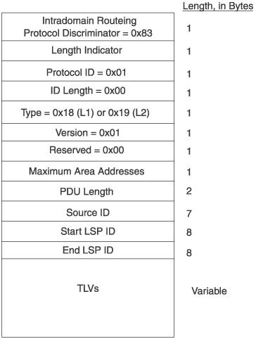
Source ID is the 6-byte SysID of the originating router plus the 1-byte Circuit ID. The Circuit ID is set to 0x00. Start LSP ID and End LSP ID together describe the contiguous range of possible LSP IDs that can be described in this CSNP. They do not necessarily describe actual LSP IDs. For example, if all the LSPs in a database can be described by a single CSNP, the Start LSP ID is 0000.0000.0000.00.00 and the End LSP ID is ffff.ffff.ffff.ff.ff: the range of all possible LSP IDs. If multiple CSNPs are necessary, the range described by these two fields is the range included in this CSNP. For example, suppose two CSNPs are required to describe the complete database. The first might have a Start LSP ID of 0000.0000.0000.00.00 and an End LSP ID of 0000.abcd.1234.00.00, whereas the second CSNP has a Start LSP ID of 0000. abcd.1234.00.01 and an End LSP ID of ffff.ffff.ffff.ff.ff. Thus, a receiving router can recognize the beginning and end of a series of CSNPs, and detect whether one or more in a series of CSNPs are missing, by observing these two fields.
Two TLVs can be carried in the CSNP: Authentication Information TLVs are for secure authentication of the packet and are discussed in Chapter 9. LSP Entries TLVs are the essential TLVs for CSNP, and uniquely identify the LSP and the specific instance of the LSP by listing the Remaining Lifetime, LSP ID, LSP Sequence Number, and Checksum fields from the LSP header. The LSP Entries TLV, shown in Figure 6.16, is identified as TLV type 9 (0x09). Figure 6.16. The format of the LSP Entries TLV. 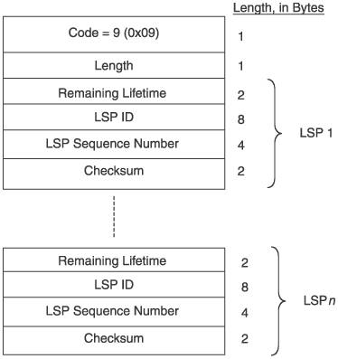
The Partial Sequence Numbers PDU (PSNP), shown in Figure 6.17, carriesas the name impliesa description of only some of the LSPs in a router's LS database. It is used both to acknowledge explicitly the receipt of LSPs (on point-to-point links) and to request needed LSPs from an L1 or L2 neighbor. Its PDU type is 26 (0x1A) for L1 and 27 (0x1B) for L2. Figure 6.17. The format of the IS-IS Partial Sequence Numbers PDU. 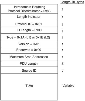
Like the CSNP, a PSNP can carry Authentication Information TLVs and LSP Entries TLVs, with LSP Entries TLVs being the essential TLV for describing LSPs. 6.2.2. Send Routing Message and Send Sequence Number Flags You read briefly about Send Routing Message (SRM) flags in Chapter 5, as they apply to flooding. To recap that discussion: The SRM is an internal flag. For each LSP in its LS database, IS-IS creates a set of SRMsone per link. That is, if a router has 20 LSPs in its LS database and 5 interfaces, 5 SRMs will be associated with each of the LSPs for a total of 100 SRMs. When IS-IS determines that an LSP needs to be sent on a particular link, it sets the LSP's SRM flag for that interface. At a set interval, known as the minimum LSP transmission interval, the LS database is scanned. On point-to-point links, all LSPs that have the SRM for that link set are sent. On broadcast links, the behavior is more interesting: The LS database is scanned once every minimum LSP transmission interval and out of the set of LSPs with their SRMs set for that interface, one[3] is randomly chosen and sent. This randomization prevents multiple routers from sending the same LSP to the DIS at the same time. [3] Some IS-IS implementations might randomly choose more than one LSP for transmission at each scan, but it must be a small number. ISO 10589 recommends no more than 10.
SRM flags are used not only as a part of the flooding procedure but also as a part of the database synchronization procedure. The flag is set when the associated LSP is to be sent on the associated interface. On broadcast circuits the flag is cleared as soon as the LSP is sent, and on point-to-point circuits the flag is cleared only when the sent LSP is acknowledged. In this, SRM flags perform a function similar to the OSPF Link State Transmission list. A key difference, however, is that where the OSPF Transmission list is associated with a neighbor (as a part of the OSPF neighbor data structure), the SRM is associated with an interface. Another internal flag used in the LS database synchronization procedure is the Send Sequence Number (SSN) flag. Like the SRM flag, each LSP has one SSN flag for each of the router's IS-IS interfaces. When an SSN flag is set, it indicates that the LSP is to be described in a PSNP sent on the associated interface. The SSN flag is cleared when the PSNP describing the LSP is sent. The SSN flag, then, performs a function similar to the OSPF Link State Request list during database synchronization. But again, the difference is that the SSN flag is associated with an interface rather than a specific neighbor. The use of these flags and the synchronization procedure itself are different on point-to-point and broadcast networks. The next two sections discuss the synchronization procedure for these two network types. 6.2.3. Synchronization on Point-to-Point Networks When an adjacency is newly established on a point-to-point link, the neighbors set the SRM flags of all LSPs for the interface attached to the link and then describe their complete databases to each other using CSNPs. L1 CSNPs are sent for L1 adjacencies, and L2 CSNPs are sent for L2 adjacencies. Each neighbor compares each LSP described in the received CSNPs with the LSPs in its own database. The comparison is sequential between the LSP IDs in the CSNP and the LSP IDs in the database, through the range of LSP IDs specified in the CSNP's Start LSP ID and End LSP ID fields. At each comparison, one of the following actions is taken: If the LSP is the same as an existing LSP in the database, clear the LSP's SRM flag associated with that interface. If the LSP is unknown (no equivalent LSP ID exists in the database), create an entry for the LSP in the database with a sequence number of 0, indicating that no information yet exists for the LSP. LSPs with sequence number 0 cannot have a SRM flag set, so they cannot be flooded. Set the entry's SSN flag for the interface, so that a PSNP describing this LSP will be sent to the neighbor. If the database contains a newer copy of the LSP, clear the LSP's SSN flag and set the SRM flag for this interface so that the LSP will be unicast to the neighbor. If the database contains an older copy of the LSP, clear the LSP's SRM flag and set the SSN flag for this interface so that the existing LSP will not be flooded to the neighbor and a PSNP describing this LSP will be unicast to the neighbor. If an LSP exists in the database whose LSP ID is in the range specified by the CSNP's Start and End LSP ID fields but is not described in the LSP Entries TLV (and the LSP has a non-zero sequence number and remaining lifetime), set the LSP's SRM flag for the interface so that it is sent to the neighbor.
On point-to-point links, PSNPs serve as acknowledgments of received LSPs. When a router sends an LSP to its neighbor, the SRM flag remains set for that interface. Every minimumLSPTransmissionInterval5 secondsLSPs that have had their SRM flags for the interface set and have not been transmitted on the interface in the past 5 seconds are retransmitted. When the neighbor acknowledges the receipt of the LSP in a PSNP, the router clears the SRM flag so the LSP is no longer retransmitted. When a router receives an LSP, it takes one of the following actions: If the LSP is newer than a copy in the database (or contains an entry with a sequence number of 0), replace the existing LSP with the new one. Set the SRM flag for all interfaces other than the one the LSA was received on, and clear the flag on this interface, so the new LSP is flooded to all neighbors except the one that sent it. Set the SSN flag for this receiving interface so that a PSNP will be sent acknowledging the LSP. If the database does not contain an LSP whose ID matches the received LSP, install the LSP in the database. Then, as with newer LSPs as described in the preceding bullet, set the SRM flag for all interfaces other than the one it was received on, and clear the flag on this interface so that the new LSP is flooded to neighbors except the one that sent it. Set the SSN flag for this receiving interface so that a PSNP will be sent acknowledging the LSP. If the database contains a copy of the LSP that is newer than the received LSP, set the LSP's SRM flag for the interface so that the newer copy will be sent to the neighbor. Clear the LSP's SSN flag for the interface. If the database contains the same instance of the received LSP, clear the LSP's SRM flag for the interface and set the SSN flag, so that a PSNP is sent acknowledging receipt of the LSP.
Note that when an adjacency first comes up, as described in the first paragraph of this section, the router sets the SRM flag for this interface in all of the LSPs in its database. This way even if the LSP is not requested by the neighbor in a PSNP, the LSP will be sent after the minimumLSPTransmissionInterval of 5 seconds and every 5 seconds afterward, until the LSP is acknowledged or a newer copy is received. Interestingly, this means that because the SRM mechanism triggers flooding, database synchronization would take place even without the CSNPs. The CSNPs provide an optimization so that only the LSPs required by each of the neighbors are exchanged. 6.2.4. Synchronization on Broadcast Networks Just as all OSPF routers on a broadcast network synchronize their databases with the DR, all IS-IS routers on a broadcast network synchronize their databases with the DIS. But the similarity ends there. One significant difference is that rather than have separate multicast addresses for the DIS and all other routers, as OSPF does for DR/BDRs and DROthers, IS-IS multicast addresses on broadcast networks distinguish only between L1 and L2 adjacencies. CSNPs, PSNPs, and LSPs are all multicast, and all routers on the broadcast network receive them equally. So, for example, if a router sends a PSNP to request an LSP, other routers that might also need the LSP can see that the LSP has been requested. And when any router sends an LSP, all routers see it and can keep a copy if needed. A DIS describes its complete database in CSNPs every CompleteSNPInterval, which typically is 10 seconds but is configurable between 0 and 65,535 seconds.[4] But rather than unicast, the CSNPs are multicast so that all attached routers see them. When a router receives a CSNP, it performs the same sequential comparison to its database, as described in Section 6.2.3 for point-to-point synchronization. [4] Although the configurable range of the CompleteSNPInterval is large, there is seldom if ever any reason to change the default period. Recall from Chapter 5 that unlike OSPF, IS-IS does not have an acknowledgment message. Instead, LSPs are implicitly acknowledged on broadcast networks by CSNPs. A long CompleteSNPInterval will inhibit these acknowledgments, and a period lower than the default does not significantly improve them.
But when an LSP is multicast, the SRM flag for the interface is cleared rather than remaining set as with point-to-point links. The reason for this is that the periodic CSNPs act as an indirect acknowledgment. If a non-DIS router sends an LSP that is not received by the DIS, the router will know it when the subsequent CSNP does not describe the LSP. The LSP can then be re-sent. Likewise, if a router on the broadcast network does not receive an LSP, the router will re-request the LSP in a new PSNP when the CSNP is again sent. Receipt of LSPs also is handled as described in Section 6.2.3, with the exception that if the LSP is newer than or equal to an LSP in the database, the SSN flag is not set. As a result, PSNPs are not sent to acknowledge receipt of these LSPs. This approach avoids a situation in which many routers on the network might try to acknowledge an LSP at the same time, and is accomplished without reducing reliability by the periodic transmission of CSNPs. As mentioned briefly in Section 5.1.2, the LS database is scanned once every minimum LSP transmission interval, and out of the set of LSPs with their SRMs set for that interface, one[5] is randomly chosen and sent. This procedure spreads the burden of updating LSPs across as many routers as possible. Because all of the IS-IS packets on the broadcast network are multicast, all routers see what is going on during the synchronization process. So, if one router sends a PSNP requesting a set of LSPs, all routers see it. If the requesting router is new, all routers likely have a copy of the requested LSPs; but only the DIS will send an LSP in response to a PSNP, to avoid multiple copies of the LSP being sent on the link. Where OSPF routers are strictly synchronized to the DR, the IS-IS DIS acts more as a reference point by sending CSNPs. Likewise, an LSP multicast on a broadcast network at the request of one router can be received by multiple routers needing the LSP. [5] Some IS-IS implementations might randomly choose more than one LSP for transmission at each scan, but it must be a small number. ISO 10589 recommends no more than 10.
6.2.5. Troubleshooting: Reading IS-IS Log Entries and Debug Output Just as you need to be able to read log entries tracking database synchronization for OSPF when a check of all the more obvious potential problem sources does not reveal why two neighbors will not synchronize, the same holds true for IS-IS. Figures 6.18 and 6.19 show two routers synchronizing their databases. The two routers are a Juniper (Juniper6) and a Cisco (Cisco8). As you read through the two routers' accounts of the synchronization, ask yourself the following questions: What are the MAC addresses of the two interfaces? What are the IP addresses of the two interfaces? For each router, is the interface L1 only, L2 only, or L1/L2? Is this an L1 or L2 adjacency? What are the LSP IDs of the LSPs sent by each router? From the perspective of each router, when is bidirectional communication first established?
Figure 6.18. A traceoptions log (JUNOS) of an IS-IS database synchronization.[View full width] jeff@Juniper6> show log isis_sync Dec 28 22:01:48 ISIS link layer change on  interface fe-4/0/0.0 Dec 28 22:01:48 ISIS interface fe-4/0/0.0 up Dec 28 22:01:48 ISIS interface fe-4/0/0.0 up Dec 28 22:01:50 Received L2 LAN IIH, source id Cisco8 on fe-4/0/0.0 Dec 28 22:01:50 intf index 5 addr 0.e0.1e.60.a .3e, snpa 0:e0:1e:60:a:3e Dec 28 22:01:50 max area 0, circuit type l1l2, packet length 1497 Dec 28 22:01:50 hold time 10, priority 64, circuit id Cisco8.01 Dec 28 22:01:50 speaks IP Dec 28 22:01:50 area address 47.0020 (3) Dec 28 22:01:50 IP address 192.168.7.2 Dec 28 22:01:50 1443 bytes of total padding Dec 28 22:01:50 new neighbor for Cisco8 Dec 28 22:01:50 new adjacency for Cisco8 on fe-4/0 /0.0, level 2 Dec 28 22:01:50 Adjacency state change, Cisco8, state New -> Initializing Dec 28 22:01:50 interface fe-4/0/0.0, level 2 Dec 28 22:01:51 Sending L2 LAN IIH on fe-4/0/0.0 Dec 28 22:01:51 max area 0, circuit type l2 Dec 28 22:01:51 neighbor 0:e0:1e:60:a:3e Dec 28 22:01:51 No candidates for DR Dec 28 22:01:51 hold time 27, priority 64, circuit id Juniper6.05 Dec 28 22:01:51 speaks IP Dec 28 22:01:51 speaks IPv6 Dec 28 22:01:51 IP address 192.168.7.1 Dec 28 22:01:51 area address 47.0103 (3) Dec 28 22:01:51 1429 bytes of total padding Dec 28 22:01:51 Received L2 LAN IIH, source id Cisco8 on fe-4/0/0.0 Dec 28 22:01:51 intf index 5 addr 0.e0.1e.60.a .3e, snpa 0:e0:1e:60:a:3e Dec 28 22:01:51 max area 0, circuit type l1l2, packet length 1497 Dec 28 22:01:51 hold time 10, priority 64, circuit id Cisco8.01 Dec 28 22:01:51 speaks IP Dec 28 22:01:51 area address 47.0020 (3) Dec 28 22:01:51 IP address 192.168.7.2 Dec 28 22:01:51 neighbor 0:d0:b7:7f:d:5 (ourselves) Dec 28 22:01:51 1435 bytes of total padding Dec 28 22:01:51 updating neighbor Cisco8 Dec 28 22:01:51 Adjacency state change, Cisco8, state Initializing -> Up Dec 28 22:01:51 interface fe-4/0/0.0, level 2 Dec 28 22:01:51 Updating LSP Dec 28 22:01:51 Scheduling L2 LSP Juniper6 .00-00 sequence 0x8a on interface fe-4/0/0.0 Dec 28 22:01:51 Sending L2 LSP Juniper6.00-00 on interface fe-4/0/0.0 Dec 28 22:01:51 sequence 0x8a, checksum 0x3d2a , lifetime 1200 Dec 28 22:01:52 Received L2 LSP Cisco8.00-00, interface fe-4/0/0.0 Dec 28 22:01:52 from Cisco8 Dec 28 22:01:52 sequence 0x9, checksum 0xce83, lifetime 1199 Dec 28 22:01:52 max area 0, length 78 Dec 28 22:01:52 no partition repair, no database overload Dec 28 22:01:52 IS type 3, metric type 0 Dec 28 22:01:52 area address 47.0020 (3) Dec 28 22:01:52 speaks IP Dec 28 22:01:52 dyn hostname Cisco8 Dec 28 22:01:52 IP address 192.168.7.2 Dec 28 22:01:52 IS neighbors: Dec 28 22:01:52 IS neighbor Cisco8.01 Dec 28 22:01:52 internal, metrics: default 10 Dec 28 22:01:52 IP prefix 192.168.7.0 255.255 .255.0 Dec 28 22:01:52 internal, metrics: default 10 Dec 28 22:01:52 Updating LSP Dec 28 22:01:52 Received L2 LSP Cisco8.01-00, interface fe-4/0/0.0 Dec 28 22:01:52 from Cisco8 Dec 28 22:01:52 sequence 0x7, checksum 0xdcee, lifetime 1199 Dec 28 22:01:52 max area 0, length 52 Dec 28 22:01:52 no partition repair, no database overload Dec 28 22:01:52 IS type 3, metric type 0 Dec 28 22:01:52 IS neighbors: Dec 28 22:01:52 IS neighbor Cisco8.00 Dec 28 22:01:52 internal, metrics: default 0 Dec 28 22:01:52 IS neighbor Juniper6.00 Dec 28 22:01:52 internal, metrics: default 0 Dec 28 22:01:52 Updating LSP Dec 28 22:01:52 Adding a half link from Cisco8.01 to Juniper6.00 Dec 28 22:01:52 Adding a half link from Cisco8.01 to Cisco8.00 Dec 28 22:01:55 Received L2 CSN, source Cisco8, interface fe-4/0/0.0 Dec 28 22:01:55 LSP range 0000.0000.0000.00-00 to ffff.ffff.ffff.ff-ff Dec 28 22:01:55 packet length 163 Dec 28 22:01:55 LSP Juniper5.00-00 lifetime 672 Dec 28 22:01:55 sequence 0x4567 checksum 0x646c Dec 28 22:01:55 Matched database, matching sequence numbers Dec 28 22:01:55 LSP Juniper5.04-00 lifetime 752 Dec 28 22:01:55 sequence 0x1c checksum 0xcfb8 Dec 28 22:01:55 Matched database, matching sequence numbers Dec 28 22:01:55 LSP Juniper6.00-00 lifetime 973 Dec 28 22:01:55 sequence 0x84 checksum 0xbbcc Dec 28 22:01:55 Matched database, neighbor is out of date, sending LSP Dec 28 22:01:55 LSP Juniper7.00-00 lifetime 474 Dec 28 22:01:55 sequence 0x466c checksum 0x415a Dec 28 22:01:55 Matched database, matching sequence numbers Dec 28 22:01:55 LSP Juniper7.02-00 lifetime 705 Dec 28 22:01:55 sequence 0x26 checksum 0x1a60 Dec 28 22:01:55 Matched database, matching sequence numbers Dec 28 22:01:55 LSP Juniper7.03-00 lifetime 416 Dec 28 22:01:55 sequence 0x1f checksum 0x215f Dec 28 22:01:55 Matched database, matching sequence numbers Dec 28 22:01:55 LSP Cisco8.00-00 lifetime 1196 Dec 28 22:01:55 sequence 0x9 checksum 0xce83 Dec 28 22:01:55 Matched database, matching sequence numbers Dec 28 22:01:55 LSP Cisco8.01-00 lifetime 1196 Dec 28 22:01:55 sequence 0x7 checksum 0xdcee Dec 28 22:01:55 Matched database, matching sequence numbers Dec 28 22:01:55 Sending L2 LSP Juniper6.00-00 on interface fe-4/0/0.0 Dec 28 22:01:55 sequence 0x8a, checksum 0x3d2a , lifetime 1198 Dec 28 22:02:00 Analyzing subtlv's for Cisco8.01 Dec 28 22:02:00 IP address: 192.168.7.1 Dec 28 22:02:00 Analysis complete Dec 28 22:02:00 Scheduling L2 LSP Juniper6 .00-00 sequence 0x8b on interface fe-4/0/0.0 Dec 28 22:02:00 Sending L2 LSP Juniper6.00-00 on interface fe-4/0/0.0 Dec 28 22:02:00 sequence 0x8b, checksum 0x26e7 , lifetime 1200 jeff@Juniper6> interface fe-4/0/0.0 Dec 28 22:01:48 ISIS interface fe-4/0/0.0 up Dec 28 22:01:48 ISIS interface fe-4/0/0.0 up Dec 28 22:01:50 Received L2 LAN IIH, source id Cisco8 on fe-4/0/0.0 Dec 28 22:01:50 intf index 5 addr 0.e0.1e.60.a .3e, snpa 0:e0:1e:60:a:3e Dec 28 22:01:50 max area 0, circuit type l1l2, packet length 1497 Dec 28 22:01:50 hold time 10, priority 64, circuit id Cisco8.01 Dec 28 22:01:50 speaks IP Dec 28 22:01:50 area address 47.0020 (3) Dec 28 22:01:50 IP address 192.168.7.2 Dec 28 22:01:50 1443 bytes of total padding Dec 28 22:01:50 new neighbor for Cisco8 Dec 28 22:01:50 new adjacency for Cisco8 on fe-4/0 /0.0, level 2 Dec 28 22:01:50 Adjacency state change, Cisco8, state New -> Initializing Dec 28 22:01:50 interface fe-4/0/0.0, level 2 Dec 28 22:01:51 Sending L2 LAN IIH on fe-4/0/0.0 Dec 28 22:01:51 max area 0, circuit type l2 Dec 28 22:01:51 neighbor 0:e0:1e:60:a:3e Dec 28 22:01:51 No candidates for DR Dec 28 22:01:51 hold time 27, priority 64, circuit id Juniper6.05 Dec 28 22:01:51 speaks IP Dec 28 22:01:51 speaks IPv6 Dec 28 22:01:51 IP address 192.168.7.1 Dec 28 22:01:51 area address 47.0103 (3) Dec 28 22:01:51 1429 bytes of total padding Dec 28 22:01:51 Received L2 LAN IIH, source id Cisco8 on fe-4/0/0.0 Dec 28 22:01:51 intf index 5 addr 0.e0.1e.60.a .3e, snpa 0:e0:1e:60:a:3e Dec 28 22:01:51 max area 0, circuit type l1l2, packet length 1497 Dec 28 22:01:51 hold time 10, priority 64, circuit id Cisco8.01 Dec 28 22:01:51 speaks IP Dec 28 22:01:51 area address 47.0020 (3) Dec 28 22:01:51 IP address 192.168.7.2 Dec 28 22:01:51 neighbor 0:d0:b7:7f:d:5 (ourselves) Dec 28 22:01:51 1435 bytes of total padding Dec 28 22:01:51 updating neighbor Cisco8 Dec 28 22:01:51 Adjacency state change, Cisco8, state Initializing -> Up Dec 28 22:01:51 interface fe-4/0/0.0, level 2 Dec 28 22:01:51 Updating LSP Dec 28 22:01:51 Scheduling L2 LSP Juniper6 .00-00 sequence 0x8a on interface fe-4/0/0.0 Dec 28 22:01:51 Sending L2 LSP Juniper6.00-00 on interface fe-4/0/0.0 Dec 28 22:01:51 sequence 0x8a, checksum 0x3d2a , lifetime 1200 Dec 28 22:01:52 Received L2 LSP Cisco8.00-00, interface fe-4/0/0.0 Dec 28 22:01:52 from Cisco8 Dec 28 22:01:52 sequence 0x9, checksum 0xce83, lifetime 1199 Dec 28 22:01:52 max area 0, length 78 Dec 28 22:01:52 no partition repair, no database overload Dec 28 22:01:52 IS type 3, metric type 0 Dec 28 22:01:52 area address 47.0020 (3) Dec 28 22:01:52 speaks IP Dec 28 22:01:52 dyn hostname Cisco8 Dec 28 22:01:52 IP address 192.168.7.2 Dec 28 22:01:52 IS neighbors: Dec 28 22:01:52 IS neighbor Cisco8.01 Dec 28 22:01:52 internal, metrics: default 10 Dec 28 22:01:52 IP prefix 192.168.7.0 255.255 .255.0 Dec 28 22:01:52 internal, metrics: default 10 Dec 28 22:01:52 Updating LSP Dec 28 22:01:52 Received L2 LSP Cisco8.01-00, interface fe-4/0/0.0 Dec 28 22:01:52 from Cisco8 Dec 28 22:01:52 sequence 0x7, checksum 0xdcee, lifetime 1199 Dec 28 22:01:52 max area 0, length 52 Dec 28 22:01:52 no partition repair, no database overload Dec 28 22:01:52 IS type 3, metric type 0 Dec 28 22:01:52 IS neighbors: Dec 28 22:01:52 IS neighbor Cisco8.00 Dec 28 22:01:52 internal, metrics: default 0 Dec 28 22:01:52 IS neighbor Juniper6.00 Dec 28 22:01:52 internal, metrics: default 0 Dec 28 22:01:52 Updating LSP Dec 28 22:01:52 Adding a half link from Cisco8.01 to Juniper6.00 Dec 28 22:01:52 Adding a half link from Cisco8.01 to Cisco8.00 Dec 28 22:01:55 Received L2 CSN, source Cisco8, interface fe-4/0/0.0 Dec 28 22:01:55 LSP range 0000.0000.0000.00-00 to ffff.ffff.ffff.ff-ff Dec 28 22:01:55 packet length 163 Dec 28 22:01:55 LSP Juniper5.00-00 lifetime 672 Dec 28 22:01:55 sequence 0x4567 checksum 0x646c Dec 28 22:01:55 Matched database, matching sequence numbers Dec 28 22:01:55 LSP Juniper5.04-00 lifetime 752 Dec 28 22:01:55 sequence 0x1c checksum 0xcfb8 Dec 28 22:01:55 Matched database, matching sequence numbers Dec 28 22:01:55 LSP Juniper6.00-00 lifetime 973 Dec 28 22:01:55 sequence 0x84 checksum 0xbbcc Dec 28 22:01:55 Matched database, neighbor is out of date, sending LSP Dec 28 22:01:55 LSP Juniper7.00-00 lifetime 474 Dec 28 22:01:55 sequence 0x466c checksum 0x415a Dec 28 22:01:55 Matched database, matching sequence numbers Dec 28 22:01:55 LSP Juniper7.02-00 lifetime 705 Dec 28 22:01:55 sequence 0x26 checksum 0x1a60 Dec 28 22:01:55 Matched database, matching sequence numbers Dec 28 22:01:55 LSP Juniper7.03-00 lifetime 416 Dec 28 22:01:55 sequence 0x1f checksum 0x215f Dec 28 22:01:55 Matched database, matching sequence numbers Dec 28 22:01:55 LSP Cisco8.00-00 lifetime 1196 Dec 28 22:01:55 sequence 0x9 checksum 0xce83 Dec 28 22:01:55 Matched database, matching sequence numbers Dec 28 22:01:55 LSP Cisco8.01-00 lifetime 1196 Dec 28 22:01:55 sequence 0x7 checksum 0xdcee Dec 28 22:01:55 Matched database, matching sequence numbers Dec 28 22:01:55 Sending L2 LSP Juniper6.00-00 on interface fe-4/0/0.0 Dec 28 22:01:55 sequence 0x8a, checksum 0x3d2a , lifetime 1198 Dec 28 22:02:00 Analyzing subtlv's for Cisco8.01 Dec 28 22:02:00 IP address: 192.168.7.1 Dec 28 22:02:00 Analysis complete Dec 28 22:02:00 Scheduling L2 LSP Juniper6 .00-00 sequence 0x8b on interface fe-4/0/0.0 Dec 28 22:02:00 Sending L2 LSP Juniper6.00-00 on interface fe-4/0/0.0 Dec 28 22:02:00 sequence 0x8b, checksum 0x26e7 , lifetime 1200 jeff@Juniper6>
|
Figure 6.19. A debug output (IOS) of the same database synchronization, from the viewpoint of the other neighbor.[View full width] Cisco8# 17:15:39: %LINEPROTO-5-UPDOWN: Line protocol on Interface Ethernet0, changed state to up Dec 28 22:01:50: ISIS-Adj: Sending L1 LAN IIH on Ethernet0, length 1497 Dec 28 22:01:50: ISIS-Adj: Sending L2 LAN IIH on Ethernet0, length 1497 Dec 28 22:01:51: ISIS-Adj: Rec L2 IIH from 00d0 .b77f.0d05 (Ethernet0), cir type L2, cir id 0192.0168.0006.05, length 1492 Dec 28 22:01:51: ISIS-Adj: New adjacency, level 2 for 00d0.b77f.0d05 Dec 28 22:01:51: ISIS-Adj: Sending L2 LAN IIH on Ethernet0, length 1497 Dec 28 22:01:51: ISIS-Upd: Received LSP from SNPA 00d0.b77f.0d05 (Ethernet0) without adjacency Dec 28 22:01:52: ISIS-Upd: Building L1 LSP Dec 28 22:01:52: ISIS-Upd: Full SPF required Dec 28 22:01:52: ISIS-Upd: Building L2 LSP Dec 28 22:01:52: ISIS-Upd: Full SPF required Dec 28 22:01:52: ISIS-Adj: Adjacency state goes to Up Dec 28 22:01:52: ISIS-Adj: Run level-2 DR election for Ethernet0 Dec 28 22:01:52: ISIS-Adj: No change (it's us) Dec 28 22:01:52: ISIS-Upd: Building L2 pseudonode LSP for Ethernet0 Dec 28 22:01:52: ISIS-Upd: Full SPF required Dec 28 22:01:52: ISIS-Upd: Sending L2 LSP 0192 .0168.0008.00-00, seq 9, ht 1199 on Ethernet0 Dec 28 22:01:52: ISIS-Upd: Sending L2 LSP 0192 .0168.0008.01-00, seq 7, ht 1199 on Ethernet0 Dec 28 22:01:53: ISIS-Adj: Sending L1 LAN IIH on Ethernet0, length 1497 Dec 28 22:01:53: ISIS-Upd: Building L2 LSP Dec 28 22:01:53: ISIS-Upd: No change, suppress L2 LSP 0192.0168.0008.00-00, seq A Dec 28 22:01:55: ISIS-Snp: Sending L2 CSNP on Ethernet0 Dec 28 22:01:55: ISIS-Upd: Rec L2 LSP 0192.0168 .0006.00-00, seq 8A, ht 1194, Dec 28 22:01:55: ISIS-Upd: from SNPA 00d0.b77f .0d05 (Ethernet0) Dec 28 22:01:55: ISIS-Upd: LSP newer than database copy Dec 28 22:01:55: ISIS-Upd: Full SPF required Dec 28 22:02:00: ISIS-Adj: Run level-2 DR election for Ethernet0 Dec 28 22:02:00: ISIS-Adj: No change (it's us) Dec 28 22:02:00: ISIS-Upd: Rec L2 LSP 0192.0168 .0006.00-00, seq 8B, ht 1198, Dec 28 22:02:00: ISIS-Upd: from SNPA 00d0.b77f .0d05 (Ethernet0) Dec 28 22:02:00: ISIS-Upd: LSP newer than database copy Dec 28 22:02:00: ISIS-Upd: Full SPF required Dec 28 22:02:03: ISIS-Upd: Building L1 LSP Dec 28 22:02:03: ISIS-Upd: Important fields changed Dec 28 22:02:03: ISIS-Upd: Full SPF required Dec 28 22:02:03: ISIS-Snp: Sending L2 CSNP on Ethernet0
|
6.2.6. Troubleshooting: Comparing IS-IS LS Databases On the rare occasion that an IS-IS LS database does not match the others in the area, you need to be able to compare databases. The same strategies you saw with OSPF apply to IS-IS: A sum of the checksums tells you quickly whether the contents match. Figures 6.20 and 6.21 show the LS databases from the two routers that synchronized in the previous example. Notice that the Juniper router in this example is L2 only, whereas the Cisco is L1/L2, because it has both L1 and L2 entries in its database. Compare the databases and match the LSPs.
|