Section 5.5. Essential TLVs
5.5. Essential TLVsAs with essential LSAs, by essential TLVs I mean those that are necessary for the basic functioning of IS-IS in an IP network. Certain TLVs would be essential to IS-IS in a CLNS network, but are not necessaryor relevantto an IP network, and so are not covered in this book. Also covered here are the TLVs that enable the support of wide metrics. These are not essential to the operation of IS-IS, but are included because wide metrics are covered in this chapter. Many other TLVs are discussed in other chapters, in the context of the IS-IS features and extensions they support. The essential TLVs are:
The TLVs that enable wide metrics are:
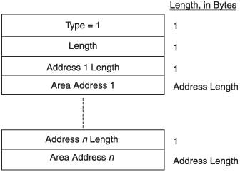
5.5.1. Area Addresses TLVThe Area Addresses TLV carries a list of all AIDs assigned to the originating router. The number of AIDs listed in this TLV adheres to the constraints of the Maximum Area Addresses field in the PDU header:
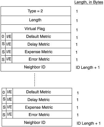
Normally, an IS-IS router has only a single AID, and so this TLV would carry only a single AID. But IS-IS does allow for the assignment of multiple AIDs to a single router, which can be useful in network migrations. Section 7.4.8 discusses the use of multiple AIDs. Figure 5.27 shows the format of the Area Addresses TLV. Its type value is 1, and both L1 and L2 LSPs carry it. It always appears before other TLVs in the LSP, which means it appears in LSPs whose LSP numbers is 0 (the first portion of a multipart LSP). It never appears in LSPs with non-0 LSP numbers. It also never appears in LSPs representing pseudonodes. Figure 5.27. The Area Addresses TLV. 5.5.2. IS Neighbors TLVThe IS Neighbors TLV (Figure 5.28) lists the originator's adjacent neighbors. The TLV type is 2, and this TLV appears in both L1 and L2 LSPs. Figure 5.28. The IS Neighbors TLV.
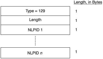
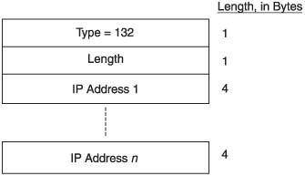
5.5.3. Protocols Supported TLVRemember that IS-IS was originally just a CLNS routing protocol. The Protocols Supported TLV (Figure 5.29), specified in RFC 1195, is essential to the extension of IS-IS to route other protocols such as IP. This TLV is type 129, and can appear in both L1 and L2 LSPs. The TLV carries a list of Network Layer Protocol Identifiers (NLPIDs) that specify the protocols supported as assigned in ISO/TR 9577. IPv4, for example, is NLPID 204 (0xCC) and IPv6 is NLPID 142 (0x8E). Figure 5.29. The Protocols Supported TLV. 5.5.4. IP Interface Addresses TLVThe IP Interface Address TLV (Figure 5.30) is specified in RFC 1195 to carry the IP addresses of the IS-IS interfaces on the originating router. These addresses are associated with the router's SNPAs. The TLV type is 132, and the TLV can appear in both L1 and L2 LSPs. Figure 5.30. The IP Interface Addresses TLV. 5.5.5. IP Internal Reachability Information TLVThe IP Internal Reachability Information TLV (Figure 5-31), specified in RFC 1195, lists the IP prefixes directly connected to the originating router, and their associated metrics. The TLV also carries any summary prefixes advertised by the originating router. The TLV type is 128, and it can appear in both L1 and L2 LSPs. However, it never appears in a pseudonode LSP. Figure 5.31. The IP Internal Reachability Information TLV.
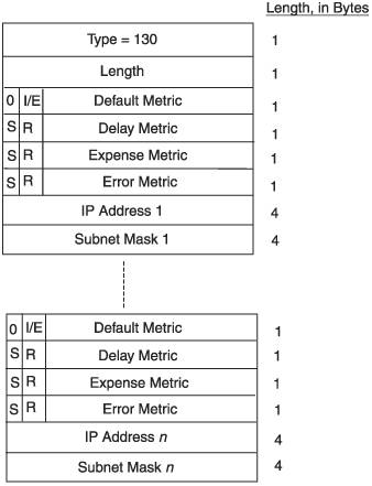
5.5.6. IP External Reachability Information TLVThe IP External Reachability Information TLV, shown in Figure 5.32, looks exactly like the Internal Reachability Information TLV except for its type number of 130. Prefixes and their subnets external to the IS-IS domain are listed in this TLV. RFC 1195 specifies that this TLV is only carried in L2 LSPs, but with most IS-IS implementations you can configure L1 LSPs to carry the LSP. Figure 5.32. The IP External Reachability Information TLV. You might expect, because the prefixes in the IP External Reachability Information TLV are external to the IS-IS domain, that the I/E bit associated with the metric would always be set to external (1). In fact, it can be set to either internal or external. The reason both for varying the I/E bit and for configuring L1 LSPs to carry this TLV is so that external prefixes can be advertised throughout the IS-IS domain, if you so desire. This issue, called domainwide prefix distribution, is discussed in more depth in Sections 7.4.6 and 7.4.7. 5.5.7. Extended IS Reachability TLVThe Extended IS Reachability TLV, along with the Extended IP Reachability TLV, was proposed to support traffic engineering by carrying much more detailed information about a link. Accordingly, these TLVs are discussed in detail in Chapter 1. For now, our interest in them is that they allow a much larger metric to be assigned to a link. The Extended IS Reachability TLV, shown in Figure 5.33, is analogous to the IS Neighbors TLV in that it describes the originating router's links to neighboring routers and the cost to those neighbors. But where that TLV wasted space with three octets of unused ToS metrics, the Extended IS Reachability TLV provides for a 24-bit default metric. Figure 5.33. The Extended IS Reachability TLV.
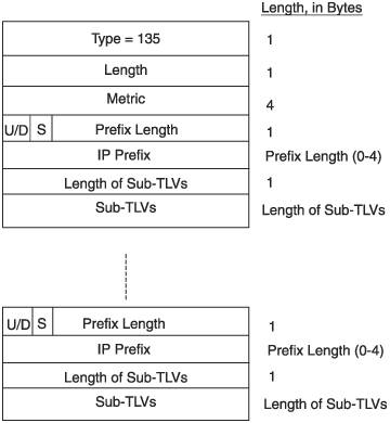
The sub-TLVs are not detailed here because they apply to traffic engineering. Chapter 11 explains these fields. 5.5.8. Extended IP Reachability TLVThe Extended IP Reachability TLV (Figure 5.34) can be used in place of both IP Internal Reachability Information and IP External Reachability Information TLVs to carry IP prefix information but with a 32-bit metric rather than a 6-bit metric. As with the Extended IS Reachability TLV, this TLV was proposed to support traffic engineering and so is detailed in Chapter 11. Figure 5.34. The Extended IP Reachability TLV.
The sub-TLVs are not detailed here because they apply to traffic engineering. Chapter 11 explains these fields. |


EAN: 2147483647
Pages: 111
- Article 360 Flexible Metallic Tubing Type FMT
- Article 410: Luminaires (Lighting Fixtures), Lampholders, and Lamps
- Article 424: Fixed Electric Space Heating Equipment
- Example No. D8 Motor Circuit Conductors, Overload Protection, and Short-Circuit and Ground-Fault Protection
- Example No. D9 Feeder Ampacity Determination for Generator Field Control