Neighbor Discovery Protocol
| The most distinct characteristics of IPv6 after its increased address space are its plug-and-play features. Neighbor Discovery Protocol (NDP) is the enabler of these plug-and-play features, using the following functions:
NDP messages should always be link-local in scope, and therefore the packets encapsulating them always use either link-local IPv6 addresses or multicast addresses with a link-local scope. To add a further layer of security, the Hop Limit of the IPv6 packet carrying all NDP messages is 255. If one of these packets is received with a Hop Limit less than that value, it means the packet has passed through at least one router, and the packet is dropped. This prevents NDP from being attacked or spoofed from a source not attached to the local link. NDP MessagesNDP is defined in RFC 2461. It uses ICMPv6 to exchange the messages necessary for its functions; specifically, five new ICMPv6 messages are specified in RFC 2461:
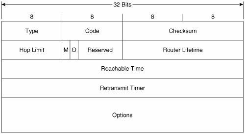
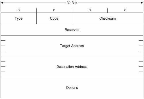
Figure 2-9 shows the format of the Router Advertisement message. Its ICMPv6 type is 134 and the code is 0. The source address of the IPv6 packet encapsulating the RA is always the IPv6 link-local address of the interface from which the packet originates. The destination address is either the all-nodes multicast address (FF02::1) if the RA is a periodic transmit, or the link-local address of the soliciting node if the RA is sent in response to a Router Solicitation. Figure 2-9. The Router Advertisement message format. Hop Limit indicates the value of the Hop Limit field that nodes attached to the link should give to any packets they originate on the link. If no Hop Limit is specified by this router, the field is set to all zeroes. M is the Managed Address Configuration flag. If this bit is set, the originating router is telling hosts on the link to use stateful address autoconfiguration via DHCPv6. If the flag is cleared, hosts on the link should use stateless address autoconfiguration. Address autoconfiguration is described later in this chapter. O is the Other Stateful Configuration flag. When set, the originating router is telling hosts on the link to use DHCPv6 for the acquisition of other link information. The M and O flags can be used together. For example, by clearing the M flag but setting the O flag, the router is telling hosts to use stateless address autoconfiguration but then consult a DHCPv6 server for other configuration parameters. Router Lifetime is set to a value other than 0 only if the originating router is a default router. In that case, this field specifies the lifetime of the default router in seconds, up to a maximum value of 18.2 hours. Reachable Time is used by the Neighbor Unreachability Detection function of NDP. It specifies the time, in milliseconds, that a node should assume a neighbor is reachable after the node has confirmed reachability of the neighbor. Retransmit Timer is used by the Address Resolution and Neighbor Unreachability Detection functions of NDP. It specifies the minimum time, in milliseconds, between retransmitted Neighbor Solicitation messages. Possible options that can be carried in the Options field of the RA include the following:
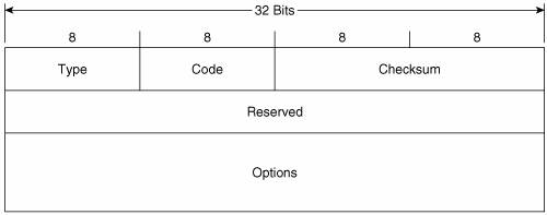
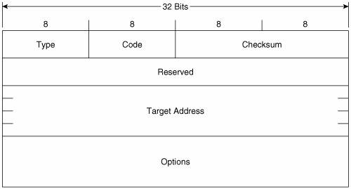
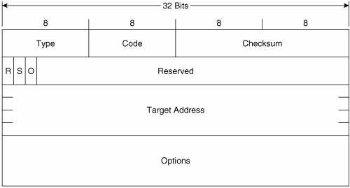
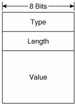
Figure 2-10 shows the format of the Router Solicitation message. Its ICMPv6 type is 133 and the code is 0. The source address of the IPv6 packet encapsulating the RS is either the IPv6 address assigned to the originating interface or, if no address has been assigned (as would be the case if the originating host is beginning address autoconfiguration), an unspecified address of :: (all zeroes). The destination address is the all-routers multicast address (FF02::2). Figure 2-10. The Router Solicitation message format. The Options field can contain the link-layer address of the originating interface, if it is known. However, the source link-layer address must not be included if the source address of the encapsulation packet is unspecified, such as when the originator is soliciting a router during address autoconfiguration. Figure 2-11 shows the format of the Neighbor Solicitation message. Its ICMPv6 type is 135 and the code is 0. The source address of the IPv6 packet encapsulating the NS is either the IPv6 address assigned to the originating interface or, if the NS is sent for Duplicate Address Detection, the unspecified address of :: (all zeroes). The destination address is either a solicited-node multicast address corresponding to the target address, or the target address. Figure 2-11. The Neighbor Solicitation message format. Target Address is the IPv6 address of the target of the solicitation. The target address is never a multicast address. The Options field of the NS can contain the link-layer address of the originating interface. Figure 2-12 shows the format of the Neighbor Advertisement message. Its ICMPv6 type is 136 and the code is 0. The source address of the IPv6 packet encapsulating the NS is always the IPv6 address assigned (or autoconfigured) to the originating interface. The destination address is either the source address of the packet containing the NS to which the NA is sent in response, or the all-nodes multicast address (FF02::1). Figure 2-12. The Neighbor Advertisement message format. R is the Router flag. When set, it indicates that the originator is a router. This bit is used during Neighbor Reachability Detection to detect a router that has changed to a host. S is the Solicited flag. This bit is set when the NA is sent in response to an NS. O is the Override flag. When set, it indicates that the information in the NA should override any existing neighbor cache entry and update the cached link-layer address. When the O bit is cleared the NA will not override an existing neighbor cache entry. Target Address is, when the NA is sent in response to a NS, the address in the Target Address field of the NS. If the NA is unsolicited (that is, sent to advertise a change of the originator's link-layer address), the Target Address is the originator's address. The Options field of the NA can contain the target link-layer addressthat is, the link-layer address of the NA's originator. Figure 2-13 shows the format of the Redirect message. Its ICMPv6 type is 137 and the code is 0. The source address of the IPv6 packet encapsulating the Redirect is always the link-local IPv6 address of the interface from which the message is originated. The destination address is always the source address of the packet that triggered the redirect. Figure 2-13. The Redirect message format. Target Address is the address of the better first-hopusually the link-local address of another router on the link. Destination Address is the IPv6 address of the destination that is redirected to the target address. The Options field of the Redirect message can contain the link-layer address of the target, and as much of the header of the packet that triggered the redirect, without making the redirect packet exceed 1280 bytes. The Options field of all of these five messages, when it contains any information, consists of one or more Type/Length/Value (TLV) triplets. Each TLV consists, as shown in Figure 2-14, of an 8-bit Type field specifying the type of information carried in the value field, an 8-bit Length field specifying the length in units of 8 octets of the value field, and the variable length Value field. Figure 2-14. The format of the TLVs used in the Options fields of the NDP messages. Table 2-6 shows the possible values and their associated type numbers. The format of the individual value fields is not provided in this chapter; consult RFC 2461 for the details on the value fields.
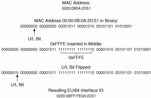
Router DiscoveryA router makes its presence known, along with any parameters it has been configured to advertise, by periodically sending RAs on its attached links. Presumably the links on which the RA do the most good are broadcast links such as Ethernet, where hosts can receive the RAs and thus learn necessary information about the link. RFC 2461 specifies that the period between transmissions of RAs should be between 4 and 1800 seconds, with a default of 600 seconds. It also specifies a minimum period between advertisements of RAs with a default of 200 seconds. The advertisements are jittered between the maximum and minimum values to prevent synchronization on a link. These unsolicited RAs are sent with their source address set to the link-local IPv6 address of the router's interface. The destination address is the all-nodes multicast address (FF02::1). Cisco routers automatically send RAs on Ethernet and FDDI interfaces whenever IPv6 is enabled on the router with the command ipv6 unicast-routing. The default interval is 200 seconds, and can be changed with the command ipv6 nd ra-interval. The Router Lifetime of the transmitted RAs is 1800 seconds by default, and can be changed with the command ipv6 nd ra-lifetime. If you do not want a router to be a default router on a link, you can use this command to set the Router Lifetime value to 0. The default Reachable Time of the RAs is 0 (which means unspecified), and can be changed with the command ipv6 nd reachable-time. The Retransmit Timer field is set to a default of 0 ms (unspecified) and can be changed with the command ipv6 nd ns-interval. The M and O flags can be set with the commands ipv6 nd managed-config-flag and ipv6 nd other-config-flag, respectively. If you do not want an interface to transmit RAs at all, you can disable them with the command ipv6 nd suppress-ra. By default, Cisco routers include in the RAs all IPv6 prefixes configured on the originating interface. You can control the prefixes advertised, and parameters associated with those prefixes, with the command ipv6 nd prefix. Of course, 200 seconds is a long time for a host that has just attached to an interface to wait for an RA so that it can find the routers and learn the link parameters. So when a host first becomes active on a link, it can send an RS to solicit the immediate transmission of an RA. The source of the RS can either be the unspecified address (::) or the host's link-local IPv6 address. The destination is always the all-routers multicast (FF02::2). When a router receives an RS, it sends (after a delay of .5 seconds) an RA in response. If the source address of the RS that triggered the RA is a host's link-local address, the RA is unicast to the host using its link-local address. If the source address of the RS was unspecified, the solicited RA is multicast to the all-nodes address. When a host receives an RA, it adds the router to its default router list (unless the RA indicates by a Router Lifetime value of 0 that it cannot be used as a default). If there is more than one router on the default router list, how the host selects a default router is implementation-specific. It could either rotate through the list, or select and keep a single router as default. In either instance, the Redirect function is essential for updating the host when a different default than the one it selected should be used. Address AutoconfigurationWhen an IPv6 host first becomes active on a link, it can self-configure its own interface address. The first step in this process is the determination of the 64-bit Interface ID portion of the address. On broadcast interfaces (where hosts are most likely to appear), a mechanism called MAC-to-EUI64 conversion is used. Quite simply, this mechanism takes the 48-bit Media Access Control (MAC) address of the interfacewhich can normally be assumed to be globally uniqueand converts it into a 64-bit Interface ID by inserting a reserved 16-bit value of 0xFFFE into the middle of the MAC address and "flipping" the Universal/Local (U/L) bit of the MAC address to 1 (Universal). Figure 2-15 illustrates this process. A MAC address, 0000:0B0A:2D51, is to be converted. The first step, shown in binary for easier understanding of what is happening, is to "split" the MAC address in the middle and insert 0xFFFE between the two 24-bit halves. The address is now 64 bits long. Next, the U/L bit of the original MAC addresswhich is always the 7th bitis flipped from 0 to 1. The resulting address, 0200:0BFF:FE0A:2D51, is now a valid 64-bit Interface ID. Figure 2-15. MAC-to-EUI64 conversion is used to create a 64-bit Interface ID from an interface's 48-bit MAC address. Of course, the Interface ID is only half of the IPv6 address; a 64-bit prefix is also required. Recall from Table 2-1 that the link-local prefix is a reserved, well-known value of 0xFF80::/10. Using this as a full 64-bit prefix (0xFF80::/64), it can be added onto the derived Interface ID, and the host now has a complete IPv6 address that can be used for communication with other devices on the same link. For example, combining the link-local prefix with the Interface ID derived in Figure 2-15 gives a link-local address of FF80::0200:0BFF:FE0A:2D51. 2-The following shows an example of a link-local address, in this case from an Ethernet interface "en1" on a Macintosh OS X host. Using the link-local prefix FF80::/10 and a MAC-to-EUI64 conversion, an IPv6 interface derives its link-local address with no help from any other device: [Jeff-Doyles-Computer:~] jdoyle% ifconfig en1 en1: flags=8863<UP,BROADCAST,SMART,RUNNING,SIMPLEX,MULTICAST> mtu 1300 inet6 fe80::211:24ff:fe23:334e prefixlen 64 scopeid 0x5 inet 10.10.24.13 netmask 0xffffff00 broadcast 10.10.24.255 ether 00:11:24:23:33:4e media: autoselect status: active supported media: autoselect [Jeff-Doyles-Computer:~] jdoyle%If the host only needs to communicate with devices on the link, autoconfiguring its link-local address is sufficient. But if it needs to communicate with devices off-link, it needs an address with a wider scopenormally a global IPv6 address. There are two ways it can acquire this address: stateful or stateless address autoconfiguration. If a host uses stateful address autoconfiguration, it consults a DHCPv6 server for the necessary address information. It might either be preconfigured to find a DHCPv6 server, or a received RA might have its M flag set telling it to use DHCPv6. DHCPv6, described in RFC 3315, is not much different in its end results than DHCP for IPv4. Much more interesting is stateless autoconfiguration. With this very simple process, the host acquires one or more link prefixes from the RAs it receives. It then adds the prefix to its previously determined Interface ID, and it now has a globally unique IPv6 address. For example, if the host from Figure 2-15 received an RA advertising a prefix of 3FFE: 1104:404:1::/64, it would add that prefix to its Interface ID for a global address of 3FFE:1104: 404:1:0200:0BFF:FE0A:2D51. Duplicate Address DetectionAlthough the use of MAC addresses to derive an Interface ID almost always guarantees a unique address of any scope, it is wise to ensure that the address is unique. So whenever a device acquires a unicast address, it must perform Duplicate Address Detection before using the address. It does not matter whether the address was acquired via stateful or stateless configuration, or if the address was statically configured. The only exception to the rule is an anycast address, because anycast addresses by definition can appear on more than one device. There is also an assumption that if a Duplicate Address Detection has been performed on a link-local address that has an Interface ID that was derived from MAC-to-EUI64 conversion, and if the address passes, other addresses using the same Interface ID will also be unique, and so the Duplicate Address Detection does not need to be repeated. A node that has acquired a new address classifies the address as tentative. The address cannot be used until the Duplicate Address Detection operation has been completed with verification that no other node on the link uses that address. The node sends an NS with the Target Address field set to the address to be verified. The source address of the NS is the unspecified address, and the destination of the NS is a solicited-node multicast address. A solicited-node multicast address is formed by prepending the prefix FF02:0:0:0:0:1: FF00::/104 to the last 24 bits of the target address. For example, given the Interface ID derived in Figure 2-15, the solicited-node multicast address is FF02::1:FF0A:2D51. The reason for this is that if a node has autoconfigured more than one interface address, the last 24 bits of all of its addresses should be the same. So the one NS with a solicited-node multicast address should match all of its interface addresses. More important, using a solicited-node multicast address ensures that if two nodes attempt to do a Duplicate Address Detection on the same address simultaneously, they will detect each other. If a node receives an NS and the target address matches one of its assigned addresses, it sends an NA with the Target Address and the destination address set to the tentative address. The node that had originated the NS, on receipt of the NA, knows that the tentative address is duplicate and cannot be used. Neighbor Address ResolutionYou know from Chapter 1 that when an IPv4 node wants to communicate with another IPv4 node on a local link, it must first discover the destination's link-layer (or data link) address. This address is then used as the destination address in the frame that encapsulates the IP packets to that node. For example, a node might want to send a packet to examplehost.com. A DNS query returns the address 3FFE:521:2400:15:211:24FF:FE23:334E. The sending node must now discover the link-layer address to use as a destination address of the frame for the local link. As the previous chapter discussed, IPv4 uses ARP for this discovery. IPv6, however, uses NDP. When the node examines the prefix of the IPv6 address returned by DNS, it either concludes that the destination is a neighbor on the local link or that it is off-link and therefore reachable through the default router. If the latter is the case, the node should already know the link-layer address of the default router from the RAs. But if the destination is on the local link, the node first looks in its neighbor cache to see if the address is known. The neighbor cache in IPv6 is very similar to the ARP cache in IPv4; it records known network-layer addresses and the link-layer addresses associated with them. The following shows a neighbor cache from a Microsoft Windows XP host. The neighbor cache stores known IPv6 addresses and their associated link-layer addresses: C:\Documents and Settings\Jeff Doyle>ipv6 nc 5: fe80::202:2dff:fe25:5e4c 00-02-2d-25-5e-4c permanent 4: fe80::260:83ff:fe7b:2df3 00-60-83-7b-2d-f3 stale (router) 4: fe80::210:a4ff:fea0:bc97 00-10-a4-a0-bc-97 permanent 4: 3ffe:3700:1100:1:210:a4ff:fea0:bc97 00-10-a4-a0-bc-97 permanent 4: 3ffe:3700:1100:1:d9e6:b9d:14c6:45ee 00-10-a4-a0-bc-97 permanent 4: 2001:468:1100:1:210:a4ff:fea0:bc97 00-10-a4-a0-bc-97 permanent 4: 2001:468:1100:1:d9e6:b9d:14c6:45ee 00-10-a4-a0-bc-97 permanent 3: 2002:c058:6301::c058:6301 192.88.99.1 permanent 3: 2002:836b:213c::836b:213c 131.107.33.60 permanent 3: 2002:4172:a85b::4172:a85b 127.0.0.1 permanent 3: 2002:836b:213c:1:e0:8f08:f020:6 131.107.33.60 permanent 3: 2001:708:0:1::624 incomplete 2: ::65.114.168.91 127.0.0.1 permanent 2: fe80::5efe:65.114.168.91 127.0.0.1 permanent 2: fe80::5efe:169.254.113.126 127.0.0.1 permanent 1: fe80::1 permanent 1: ::1 permanent If the address is not in the neighbor cache, it is entered but tagged Incomplete, indicating that address resolution is in progress. The node then sends an NS to the solicited-node multicast address associated with the target node. The NS should include the Source Link-Layer option (type 1), so that the solicited node would have the link-layer address of the soliciting node, and therefore would know where to send the responding NA. If a value other than 0 is included in the RAs, multiple NSs can be sent at that specified interval. If the Retransmit Timer value in the RAs is unspecified (0), the NS is retransmitted every 1000 ms until an NA is received. If no NA is received from the solicited node after three NS transmissions, the neighbor address resolution has failed and an ICMP message of type 1/code 3 (Destination Unreachable/Address Unreachable) is returned for each packet queued for transmission to the now unknown destination. If the solicited node exists and the NS is valid, it responds with an NA. The Target Address field of the NA is set to the value of the Target Address field of the NS that triggered it. The soliciting node, upon receipt of the NA, can add the target node's link-layer address to the neighbor cache entry and change the entry from Incomplete to Reachable. The neighbor cache of a Cisco router can be observed with the command show ipv6 neighbors, as shown in Example 2-1. Example 2-1. The neighbor cache of a Cisco router can be displayed with the command show ipv6 neighbors.Confucius# show ipv6 neighbors IPv6 Address Age Link-layer Addr State Interface 2001:201:1502:1:210:a4ff:fea0:bc97 0 0010.a4a0.bc97 REACH Ethernet0 fe80::210:a4ff:fea0:bc97 0 0010.a4a0.bc97 REACH Ethernet0 fe80::260:83ff:fe4c:5df2 0 0060.834c.5df2 REACH Ethernet0 3ffe:1300:a47:20:d9e6:b9d:14c6:45ee 0 0002.2d25.5e4c REACH Ethernet1Privacy AddressesThe stateless address autoconfiguration has raised a security concern for some: Even if a device moves from subnet to subnet or even major network to major network, its Interface ID always remains the same; and if the Interface ID remains the same, it can be tracked. At the least, this becomes a privacy issue. For example, suppose you are using IPv6 to connect to your company network. Recording and analyzing packets coming into some part of the network can identify you by your unchanging Interface ID. And by further analyzing the different prefixes prepended to that Interface ID, your employer can infer where you are at all times: at work, at home, traveling, or whatever. More insidious uses can also be made of such tracking, keeping record of your location and activities for everything from marketing to criminal exploitation. RFC 3041 addresses this security concern by defining IPv6 privacy addresses. A privacy address is one in which the Interface ID is generated by an algorithm using a pseudo-random number. What is significant about it, and makes it reasonably private, is that the Interface ID changes approximately once a day (or on some configurable period) and also whenever the node acquires a new IPv6 prefix. Of course, a constantly changing address is not practical for reachability. Nodes that want to communicate with you, and hence DNS servers, must know you by only one or a few static addresses. So the standard statelessly configured IPv6 address remains your public address. Anyone wanting to send packets to you uses this address as the destination. But when you send packets back, you use the private address. This is a bit like having Caller ID in your home but blocking your number from appearing on anyone else's Caller ID. You can see who is calling you, but others cannot see your number when you call them. The following shows the addresses assigned to a Microsoft Windows XP machine. There are two public IPv6 addresses assigned to the interface, and you can see that although the prefixes are different, the MAC-to-EUI64generated Interface IDs are the same. You can easily identify the public Interface IDs by the 0xFFFE inserted in the middle. But for both of these public addresses there is also a private address (which Windows labels as "anonymous"). These private addresses are created by prepending the RA-discovered IPv6 prefix onto the randomly generated Interface ID. Public and private (called "anonymous" here) are used together to create anonymity for the host but at the same time maintain reachability: C:\Documents and Settings\Jeff Doyle>ipv6 if 4 Interface 4: Ethernet: Local Area Connection 2 uses Neighbor Discovery uses Router Discovery link-layer address: 00-10-a4-a0-bc-97 preferred global 2001:484:1200:1:d9e6:b9d:14c6:45ee, life 6d21h14m26s/21h12m4s (anonymous) preferred global 2001:468:1200:1:210:a4ff:fea0:bc97, life 29d23h59m25s/6d23h59m25s (public) preferred global 3ffe:3705:1200:1:d9e6:b9d:14c6:45ee, life 6d21h14m26s/21h12m4s (anonymous) preferred global 3ffe:3705:1200:1:210:a4ff:fea0:bc97, life 29d23h59m25s/6d23h59m25s (public) preferred link-local fe80::210:a4ff:fea0:bc97, life infinite multicast interface-local ff01::1, 1 refs, not reportable multicast link-local ff02::1, 1 refs, not reportable multicast link-local ff02::1:ffa0:bc97, 3 refs, last reporter multicast link-local ff02::1:ffc6:45ee, 2 refs, last reporter link MTU 1500 (true link MTU 1500) current hop limit 64 reachable time 22000ms (base 30000ms) retransmission interval 1000ms DAD transmits 1 Neighbor Unreachability DetectionThe discussion of neighbor address resolution in a previous section made mention of neighbor cache entries being labeled as Incomplete or Reachable. In fact, a neighbor cache entry can be in one of five states:
Reachability of a neighbor is confirmed in one of two ways:
Neighbor Unreachability Detection confirms not just reachability from the neighbor's perspective, but confirms two-way reachability from the local node's perspective. For this reason, an unsolicited NA or RA cannot change the state of a neighbor cache entry to Reachable; the received message only indicates one-way reachability from the originating node to the local node. Two-way reachability is confirmed only by either a remote response to a transmitted message (such as an ACK of a TCP packet) or an RA or NA sent in response to a solicitation. |
EAN: 2147483647
Pages: 233
- The Effects of an Enterprise Resource Planning System (ERP) Implementation on Job Characteristics – A Study using the Hackman and Oldham Job Characteristics Model
- Context Management of ERP Processes in Virtual Communities
- Data Mining for Business Process Reengineering
- A Hybrid Clustering Technique to Improve Patient Data Quality
- Development of Interactive Web Sites to Enhance Police/Community Relations