Internet Protocol
| Internet Protocol (IP) is the core network-layer protocol of the TCP/IP protocol suite. It's a pervasive protocol, used by innumerable hosts worldwide to deliver data across the Internet and private networks. It provides an infrastructure so that computers can locate each other with unique identifiers (IP addresses) and exchange blocks of data (known as IP datagrams). IP is designed to abstract the physical details of networking hardware so that communication can happen more or less seamlessly. At the level immediately below IP, you find protocols targeted to specific networking hardware, such as Ethernet and token ring. Sitting on top of IP, you find protocols such as TCP that provide features such as ports, connections, and reliable delivery of data. Naturally, any host participating in a TCP/IP based network must be able to correctly process incoming IP datagrams. The host performs this processing immediately upon reception of a packet, and makes decisions on how the packet should be handledwhether that includes passing it to a higher-level protocol handler in the network stack (such as TCP or UDP), signaling an error because the packet cannot be processed, or blocking the packet because it fails to meet criteria of a firewall or other similar data inspection software. Because of the placement of IP in the network stack and the role it plays, it is an attractive strategic target for attackers trying to penetrate a system or network. They can target errors in processing IP datagrams to exploit devices and hosts, or attempt to fool security systems (firewalls, IDSs, IPSs) by leveraging some of the unusual nuances of IP stacks. A large codebase dealing entirely with untrusted user data received from a remote location is always a prime candidate for code reviewers because it represents a major attack surface. Before you dive into how to audit IP processing code, you should briefly review the basics of how IP works. As mentioned, the discussion in this chapter is specific to IP version 4commonly written as IPv4. Interested readers can get a more comprehensive analysis from several sources on the subject, particularly RFC 791 (www.ietf.org) and TCP/IP Illustrated, Volume 1 by W. Richard Stevens (Addison-Wesley, 1994). IP Addressing PrimerIdentifying weaknesses in IP processing code is more than just finding low-level flaws such as integer wraps or buffer overflows; you also must recognize logic problems with how traffic is processed. This requires a good working knowledge of how basic routing is performed, so that you can assess how potentially dangerous packets arrive at a destination, and where they can originate from. As such, the following paragraphs are dedicated to providing a brief examination of the IP routing facilities present on a typical host. To communicate with other hosts on a network, a machine must have at least one network interface. A network interface is simply a network device that contains a unique hardware address and can be used to send and receive data over a network. A network interface is a software abstraction provided by the OS kernel in that it's a virtual device, though it obviously must be associated with a physical network device if you expect to send data to external nodes. Although it is possible to have several interfaces associated with a single network hardware device, the most common configuration for a standard host is to have just one interface per network device. Having multiple interfaces tied to the same network device is useful in a number of situations, such as establishing virtual networks over existing connected networks, or when a single machine needs to have more than one IP address on a network (perhaps because it's hosting a virtual machine). On an IP network, each connected interface has an IP address, which is a 32-bit value that uniquely identifies a host on the network that they are connected to. An IP address can be further broken down into two variable length bitfieldsa network ID and a host ID. The network ID indicates the sub-network (commonly called the subnet) that the host belongs to, and the host ID uniquely identifies the host on that particular network. Historically, the IP address space was broken down into several classes, and an IP address's network ID was determined by which class it belonged to. Classes predate the classless subnetting used today, but they are still relevant in some circumstances because certain classes are reserved for special use. The five address classes, class A through class E, are summarized here:
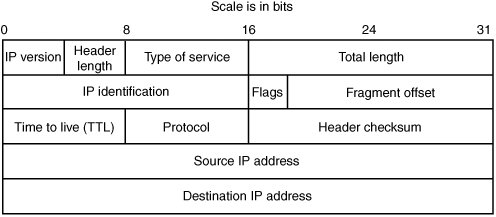
The problem with using address classes is that there are only a limited number of networks available, a number of which are reserved for various special purposes. Furthermore, the fixed-size IP address classes might not be appropriately sized for certain networks. For example, if you had 280 nodes on a network, you have just a few too many for a class C, but are only using up a fraction of a class B. As such, today's IP implementations allow for arbitrary sized network IDs. The network ID for an IP address is determined by the network mask (also known as the subnet mask, or netmask), which simply indicates which bits of the IP address are reserved for the network ID. Network masks can be expressed in one of two ways; in netmask notation or in classless inter domain routing (CIDR) notation. Netmask notation involves writing a hosts IP address followed by a bitmask with every network ID bit set to 1 and every host ID bit set to 0. For example, if you had the IP address 192.168.2.100 and the first 24 bits were used to specify the network ID, it would be written as 192.168.2.100/255.255.255.0. With CIDR notation, you express the netmask by writing the IP address followed by the size in bits of the network ID. Returning to our previous example of 192.168.2.100 with a 24 bit network ID, it would be written as 192.168.2.100/24. The network ID is used to subclass the entire IP address space into smaller, more manageable sub-networks. Breaking down networks this way enforces hierarchy upon the otherwise unstructured address space and eases the job of routing packets by keeping tables of network ranges rather than tables of individual nodes, as you will see shortly. So, IP networks are subdivided into subnets, which are groups of hosts that share the same subnet mask and network ID. All hosts in a subnet can talk to each other through the data link layer. Lower-level protocols such as the Address Resolution Protocol (ARP) help machines map data-link layer addresses to IP addresses so that they can figure out how to talk to machines on the same subnet. ARP is an integral part of the TCP/IP suite, and interested readers are encouraged to read more about it at http://en.wikipedia.org/wiki/Address_Resolution_Protocol, or from RFC 826 (www.ietf.org/rfc/rfc0826.txt?number=826). A typical IP machine has one active interfaceone connection to a network. Machines that form the routing infrastructure of IP networks have more than one interface and are responsible for routing packets between their interfaces. These machines are called gateways or routers. If a machine wants to send an IP datagram, it looks at its routing table, which has a list of simple rules. In general, a host can directly send packets only to another host in the same subnet. If a computer wants to talk to another computer in the same subnet, its routing table tells it which interface to send the packet out on. If a computer wants to talk to a host on another subnet, its routing table tells it which computer on its subnet is responsible for routing packets to the destination subnet. Naturally, the process is more complex in large networks, but this description is the basics of how packets move across the Internet. Several special IP addresses are quite important from a security perspective. Say your IP address is 10.20.30.40, and your network mask is 255.255.255.0. This means your subnet contains the 256 addresses between 10.20.30.0 and 10.20.30.255. 10.20.30.0 is called the subnet address, and any packet sent to that address is usually picked up by a subset of the hosts in the network. The address 10.20.30.255 is the directed subnet broadcast address, and packets destined there are picked up by all hosts in the subnet. The special address 255.255.255.255 also functions as a subnet broadcast address for the sender's local subnet. The security implications of these addresses are addressed in the discussion of firewall spoofing attacks in Chapter 15. IP Packet StructuresThe basic transmission unit for sending data using IP is the IP packet. An IP packet is a discrete block of data prepended with a header that contains information necessary for routing the packet to the appropriate destination. The term IP datagram is often used interchangeably with IP packet, and they are effectively synonymous. An IP datagram can be fragmented into smaller pieces and sent to the destination as one or more fragments. These fragmented packets are reassembled at the destination into the original IP datagram. The basic header definition for an IPv4 packet is shown in Figure 14-1. The IP packet header defines a small set of data elements (fields) used to help deliver the packet to its specified destination. The following list describes these fields:
Figure 14-1. IPv4 header diagram Basic IP Header ValidationBefore software can safely work with an IP datagram, the fields that make up the IP header need to be validated to ensure that the packet is legitimate. If IP processing code fails to adequately check the fields within an IP header, it will most likely be exposed to a range of potential problems. The consequences of insufficient validation depend on where the IP processing code resides in the system; failures in kernel mode processing or in embedded devices tend to have more dramatic effects than failures in userland processes. These effects can range from memory management related problems (such as a crash of the application or device, or even exploitable memory corruption conditions) to passing packets up to higher layers in ways that can cause problems with state and, ultimately, system integrity. The following sections examine some common points of inquiry. Is the Received Packet Too Small?Typically, an IP datagram is passed to the IP stack from a lower-level networking layer that hands over the data for the packet in a buffer and states how many bytes of data are in the packet. Before this data can be processed as though it's a valid IP header, you have to make sure you get at least 20 bytesthe minimum size of a valid IP header. If an implementation overlooks this check, it's likely to read memory that isn't a legitimate part of the packet. This oversight normally wouldn't lead to a major security impact unless perhaps the data is read from an unmapped page, generating a memory access violation. In the worst-case scenario, however, the IP processing code neglects to check the packet size at all, and then uses it in a way that's vulnerable to numeric overflows. For example, consider the following packet sniffer. (The author's name has been omitted because the example is old and no longer in use.) void do_pcap(u_char * udata, const struct pcap_pkthdr * hdr, const u_char * pkt) { if (hdr->caplen < ETHER_HDR_LEN) return; do_ethernet(pkt, hdr->caplen); }This code is a standard pcap callback function. The pkt parameter points to the packet data, and the hdr->caplen value is the amount of data taken from the network. The code ensures there's enough packet data for an Ethernet header, and then calls this function: int do_ethernet(const u_char * pkt, int length) { char buffer[PCAP_SNAPLEN]; struct ether_header *eth = (void*) pkt; u_char *ptr; int i; if (ntohs(eth->ether_type) != ETHERTYPE_IP) return 0; memcpy(buffer, pkt + ETHER_HDR_LEN, length - ETHER_HDR_LEN); ... code edited for brevity ... return do_ip((struct ip*)buffer, length - ETHER_HDR_LEN); }The preceding code copies the Ethernet payload into a buffer and calls do_ip(), passing that buffer and the length of the payload. Here's the code for do_ip(): int do_ip(const struct ip * ip, int length) { char buffer[PCAP_SNAPLEN]; int offset = ip->ip_hl << 2; printf("LAYER_3 -> IPv %d\t", ip->ip_v); printf("sIP %s\t", inet_ntoa(ip->ip_src)); printf("dIP %s\t", inet_ntoa(ip->ip_dst)); printf("protokols %d\n", ip->ip_p); memcpy(buffer, (void*)ip + offset, length - offset); switch(ip->ip_p) {The do_ip() function calculates offset, which is the IP header length field taken from the packet. At this point, it could be almost anything you wanted. The code then copies length offset bytes to another local stack buffer. Assume you make ip_hl the normal value of 5 so that offset is 20. If you have sent only 10 bytes of Ethernet payload, the memcpy()s count argument is -10, thus resulting in a large copy into the destination buffer. A vulnerability of this nature has only a limited impact, as these types of packets usually aren't routable and, therefore, can be sent only on a local network segment (unless the packet is encapsulated, an issue discussed in Chapter 15, "Firewalls"). Does the IP Packet Contain Options?IP packets have a variable-length header that can range between 20 and 60 bytes. The header size is specified in the first byte of the IP packet by the IP header length field. IP headers are usually just 20 bytes in length and have no options attached. IP processing code can't just assume the header is 20 bytes, however, or it will run into trouble quickly. For example, many password sniffers used to read data from the network into the following structure: struct etherpacket { struct ethhdr eth; struct iphdr ip; struct tcphdr tcp; char data[8192]; };The sniffers would then parse packets by looking at the ip and tcp structures. However, this processing worked only for the minimum length ip and tcp headers, both 20 bytes. Packets with any options set in IP or TCP aren't decoded correctly, and the sniffer will misinterpret the packet. For example, if the IP header has options attached, they will mistakenly be interpreted as the next layer protocol header (in this case, TCP). Therefore, the sniffer will see the packet with totally different TCP attributes than it really has. Is the IP Header Length Valid?Certain values for the IP header length are invalid and might cause problems if they're not accounted for correctly. Specifically, the IP header must be at least 20 bytes, so the IP header length must be at least 5 (recall that it's multiplied by 4 to get the actual IP header size). Any value less than 5 is invalid. For an example of this problem, look at an excerpt of code from an older version of the tcpdump utility: /* * print an IP datagram. */ void ip_print(register const u_char *bp, register u_int length) { register const struct ip *ip; register u_int hlen, len, off; register const u_char *cp; ip = (const struct ip *)bp; ... code edited... hlen = ip->ip_hl * 4; ... code edited... if ((hlen -= sizeof(struct ip)) > 0) { (void)printf("%soptlen=%d", sep, hlen); ip_optprint((u_char *)(ip + 1), hlen); }When ip_print() is called, tcpdump calculates the header length, hlen, by multiplying ip_hl by 4, but it doesn't check whether ip_hl is at least 5 to begin with. Then it checks to make sure (hlen -= sizeof(struct ip)) is higher than 0. Of course, this check would prevent an underflow if hlen wasn't an unsigned integer. However, because hlen is unsigned, the result of this expression is a very large positive number. As a result, the validation check is passed, and the ip_optprint() function is given an infinite amount of memory to analyze. Is the Total Length Field too Large?After enough data has been read in to obtain the IP header, IP processing code needs to examine the total length field. This value specifies the length in bytes of the total IP packet, including the header. The code must verify that enough packet data has been received from the network to match the total length specified in the IP header. If there isn't enough data in the packet to match this length, the program runs the risk of reading past the received packet contents into adjacent memory locations. Are All Field Lengths Consistent?Three different lengths are at play in an IP header: the amount of data received from the network, the length of the IP header specified in the header length field, and the length of the total packet specified in the total length field. These fields must be consistent, and the following relationships must hold:
Failure to enforce any of these conditions is likely to have consequences in the form of memory corruption due to integer wrapping problems. For example, consider what happens if the header length field is set to an invalid value in relation to the total length field. The total length field must specify that the packet is at least as many bytes as the header length field, because it makes no sense to have an IP header that is larger than the total IP packet length. A good example of a malformed packet is one with a header length of 60 bytes, but a total length of 20 or fewer bytes. Take a look at this example: int process_ip_packet(unsigned char *data) { unsigned int header_length, total_length, data_length; struct iphdr *iph; ... iph = (struct iphdr *)data; header_length = ntohs(iph->hl); total_length = ntohs(iph->tot_len); data_length = total_length header_length; ... validate ip header ... switch(iph->protocol){ case IPPROTO_TCP: return process_tcp_packet(data + header_length, data_length); ...If the total length is smaller than the header length, the data_length value underflows and the process_tcp_packet() function thinks the packet's data length is huge (around 4GB). Invariably, this error leads to memory corruption or an attempt to access data out of bounds (probably when performing a TCP checksum, as the code tries to checksum around 4GB of data). Now take a look at a real-world example to see whether you can spot the oversights in it. This code is from the 1999-era Snort 1.0, which has been edited slightly for brevity: void DecodeIP(u_char *pkt, const int len) { IPHdr *iph; /* ip header ptr */ u_int ip_len; /* length from the start of the ip hdr to the pkt end */ u_int hlen; /* ip header length */ /* lay the IP struct over the raw data */ iph = (IPHdr *) pkt; /* do a little validation */ if(len < sizeof(IPHdr)) { if(pv.verbose_flag) fprintf(stderr, "Truncated header! (%d bytes)\n", len); return; }So far, so good. There are checks in place to ensure that the packet has at least 20 bytes of data from the network before the code proceeds much farther. Next, the code makes sure the packet has at least as many bytes as are specified in the IP header: ip_len = ntohs(iph->ip_len); if(len < ip_len) { if(pv.verbose_flag) { fprintf(stderr, "Truncated packet! Header says %d bytes, actually %d bytes\n", ip_len, len); PrintNetData(stdout, pkt, len); } return; }The IP header looks valid so far, so IP options are parsed (if present): /* set the IP header length */ hlen = iph->ip_hlen * 4; if(hlen > 20) { DecodeIPOptions( (pkt + 20), hlen - 20); }Uh-oh! The code hasn't checked to make sure the packet has enough bytes to contain hlen and hasn't checked to see whether the total length is big enough to contain hlen. The result is that DecodeIPOptions() reads past the end of the packet, which probably isn't too catastrophic. Continuing on: /* check for fragmented packets */ ip_len -= hlen; pip.frag_off = ntohs(iph->ip_off); /* move the packet index to point to the transport layer */ pktidx = pktidx + hlen; switch(iph->ip_proto) { case IPPROTO_TCP: net.proto = IPPROTO_TCP; strncpy(pip.proto, "TCP", 3); DecodeTCP(pktidx, len-hlen); return;This code has several problems, including the following:
Is the IP Checksum Correct?The IP checksum is used as a basic mechanism to ensure that the packet header hasn't been corrupted en route. When the IP stack receives a new packet, it should verify that the checksum is correct and discard the packet if the checksum is erroneous. Any IP processing code that fails to do this verification is interpreting packets that should be ignored or dropped. It's rare to find code that fails to verify the checksum; however, this error might surface occasionally in packet-sniffing software. Although accepting a packet erroneously has a fairly minimal impact in this context, it might prove useful for attackers trying to evade intrusion detection. Attackers could send a packet that looks like it closes a connection (such as a TCP packet with the FIN or RST flags set) so that when the packet sniffer sees it, it stops monitoring the connection. The end host, however, silently ignores the packet with the invalid checksum. This result is more interesting in TCP checksums because those packets are routed. IP Options ProcessingIP options are optional variable-length elements that can be added to the end of an IP header to convey certain information from the sender to the destination (or intermediate routers). Options can modify attributes of the packet, such as how the datagram should be routed and whether timestamps should be added. A maximum of 40 bytes of IP options can be appended to an IP header (making the maximum total IP header size 60 bytes). Note The header length field is 4 bits and represents the IP header's length in 32-bit words. So the maximum value it can have is 0x0F (or 15), which multiplied by 4 gives 60. Before you look at what IP options are available, here's the basic structure of an IP option: struct ip_options { unsigned char option; unsigned char optlen; unsigned char data[0]; };An IP option is typically composed of a one-byte option type specifying what the option is, a one-byte length field, and a variable-length data field. All options have this format (except two, explained shortly in this section). Note The option byte is actually composed of three fields, as shown: struct optbyte { unsigned char copied:1; unsigned char class:2; unsigned char option:5; };The top bit indicates whether the option is copied into each fragment (if fragmentation occurs), and the next two bits indicate what class the IP option is. RFC 791 (www.ietf.org/rfc/rfc0791.txt?number=791) lists these available options:
IANA gives a complete list of the classes each option belongs to (www.iana.org/assignments/ip-parameters). The last five bits indicate the actual option. Most implementations ignore that the option byte has several fields and just treat it as just a one-byte option field. Given this information, you can begin applying your knowledge from Part II on variable relationships and type conversions to start locating potential problems. (The one-byte option length is related to the IP header length and, indeed, the IP total length.) The following sections cover some typical mistakes that can be made when dealing with these structures. Is the Option Length Sign-Extended?The IP options field is a single byte, and it's not unusual for code processing IP options to store that length field in an integer, which is a larger data type. As you learned in Chapter 6, "C Language Issues," these assignments cause a promotion of the smaller type (byte) to the larger type (integer) to store the length value. Furthermore, if the length byte is treated as signed, the assignment is value preservingin other words, it's sign extended. This assignment can lead to memory corruption (such as large data copies) or incorrect advancement of a pointer cycling through IP options, which can have varying consequences depending on how the code works. You see a real-world example of this problem in "TCP Options Processing" later in this chapter; TCP options have a nearly identical structure to IP options. Is the Header Big Enough to Contain the IP Option?An IP option is at least two bytes, except for the "No Operation" (NOP) option and the "End of Options List" (EOOL, or sometimes just shortened to EOL). Many options have further requirements for minimum length; a source routing option needs to be at least three bytes, for example. Sometimes IP option processing code fails to verify that these minimum length requirements are met, which often leads to either reading undefined memory contents or possibly memory corruption due to integer boundary conditions. Consider the following example: int process_options(unsigned char *options, unsigned long length) { unsigned char *ptr; int optlen, opttype; for(ptr = options; length; length -= optlen, ptr += optlen){ if(*ptr == IPOPT_NOP){ optlen = 1; continue; } if(*ptr == IPOPT_EOL) break; opttype = ptr[0]; optlen = ptr[1]; if(optlen > length) goto err; switch(opttype){ ... process options ... } } }This code cycles through options until no more are left to process. There's a slight problem, however; no check is done to ensure that at least 2 bytes are left in the buffer before the opttype and optlen values are populated. An options buffer could be constructed such that only one byte is left in the buffer when processing the final option, and the optlen byte would read out-of-bounds memory. In this situation, doing so probably wouldn't be useful (as the length check after the byte is read would ensure that the loop doesn't start skipping farther out of bounds). Code like this that processes specific options, however, can be quite dangerous because some options are modified as they are processed, and memory corruption might be possible. Is the Option Length Too Large?The variable relationship between the IP header length, IP total length, and each IP option length field specifies that the following must hold true:
When reviewing IP options processing, you must ensure that the code guarantees this relationship. Failure to do so could result in the code processing uninitialized memory, and cause memory corruption because some IP options require modifying data within the IP option itself (primarily the timestamp and source routing options). Does the Option Meet Minimum Size Requirements?As mentioned, an IP option consists of a one-byte option type and a one-byte option length followed by some variable-length data. The option length specifies the total size of the option including the length byte and type byte, so it's required to hold a minimum value of two. Code that processes options and doesn't enforce this minimum value can end up with some unique problems, as shown in the following code: int process_options(unsigned char *options, unsigned long length) { unsigned char *ptr; int optlen, opttype; for(ptr = options; length; length -= optlen, ptr += optlen){ if(*ptr == IPOPT_NOP){ optlen = 1; continue; } if(*ptr == IPOPT_EOL) break; if(length < 2) break; opttype = ptr[0]; optlen = ptr[1]; if(optlen > length) goto err; switch(opttype){ ... process options ... } } }This code correctly ensures that the length in the IP option isn't larger than the total amount of IP option bytes specified in the IP header. However, it fails to make sure it's at least 2. Supplying a value of 0 for an IP option length causes this code to enter an infinite loop. Additionally, if an IP option length of 1 is given, the next option begins where the length byte of the current option should be. This error can also have varying consequences, depending on how the code following the validation failure performs options processing. Are IP Option Bits Checked?The IP option byte is actually composed of a number of bit fields, but most implementations ignore the separate fields and treat the byte as a single value. So any implementation that actually parses the IP option byte by masking off the option bits could expose itself to potential misinterpretations of an option's meaning. To understand the problem, take a look at this example: #define OPTVALUE(x) (x & 0x1F) int process_options(unsigned char *options, size_t len) { unsigned char *optptr, *optend = options + len; unsigned char optbyte, optlen; for(optptr = options; optptr < optend; optptr += optlen){ optbyte = *optptr; if(OPTVALUE(optbyte) == EOL) break; if(OPTVALUE(optbyte) == NOP){ optlen = 1; continue; } optlen = optptr[1]; if(optlen < 2 || optptr + optlen >= optend) goto err; switch(OPTVALUE(optbyte)){ case IPOPT_LSRR: ... } } }The problem is that even though this code is correctly masking the option byte to get the lower 5 bits, the other bitfields should also be set a certain way depending on the option value. In fact, IP options are defined by the Internet Assigned Numbers Authority (IANA) by their option value as well as the other bitfield values associated with that option, and so ignoring other bitfields is technically a mistake. Note Interested readers can view the IANA IP Options List at www.iana.org/assignments/ip-parameters. To understand why this is a problem, consider a scenario where this code is in a firewall that is attempting to strip out source routing options (LSRR and SSRR). The code iterates through each option looking for the LSRR or SSRR option and then terminates when it sees the EOL option (0x00). However, only the bottom 5 bits are checked. This contrasts with how end hosts process the same optionsthey will also continue processing until encountering what they think is an EOL option, but end hosts define an EOL as an option with all 8 bits set to 0. So if the option value 0x80 is present in the packet, the firewall would interpret it as an EOL option, and the end host just assumes it's some unknown option and continues processing more option bytes. The result is that you could supply an IP option with the option value 0x80 with a valid source routing option following it, and the firewall wouldn't catch it. Now consider this code in a client host with the same requirementsa firewall having to strip out source routing options. In this case, the firewall is looking for an 8-bit source routing option, such as 0x89. If the value 0x09 is sent, the firewall treats it as an unknown option, and the end host sees it as a source route because it has masked off the top three bits. Unique ProblemsAs always, lists of typical errors aren't exhaustive, as unique implementations can bring about unique problems. To illustrate, this section presents an example that was present in the Solaris 8 IP stack. The Solaris code for processing IP options for datagrams destined for a local interface had an interesting problem in the way it calculated the options length. A code snippet is shown: #define IP_VERSION 4 /* edited for brevity */ #define IP_SIMPLE_HDR_LENGTH_IN_WORDS 5 uint8_t ipoptp_first(ipoptp_t *optp, ipha_t *ipha) { uint32_t totallen; /* total length of all options */ totallen = ipha->ipha_version_and_hdr_length - (uint8_t)((IP_VERSION << 4) + IP_SIMPLE_HDR_LENGTH_IN_WORDS); totallen <<= 2; optp->ipoptp_next = (uint8_t *)(&ipha[1]); optp->ipoptp_end = optp->ipoptp_next + totallen; optp->ipoptp_flags = 0; return (ipoptp_next(optp)); }This code treats the first two fields of the IP header as a single field with two components, which isn't uncommon, as both fields occupy four bits in the same byte. However, when the code obtains the IP header length from this byte, it does so by subtracting the standard IP version value (which is 4, and because it occupies the high four bits in this byte, 0x40) from the byte, as well as the static value IP_SIMPLE_HDR_LENGTH_IN_WORDS, defined elsewhere as 5. In essence, the developer assumes that subtracting the static value 0x45 from the first byte of the IP header will leave you with the size of the IP options trailing the basic header. Not masking off the version field is a dangerous practice though; what if the IP version is 15 (0xF)? The code's calculation could erroneously conclude that 744 bytes worth of IP options are appended to the IP header! Of course, a sanity check earlier in the code ensures that the size of the packet received is at least the size specified in the total length and header length fields. However, this other sanity check is done differentlyit does mask off the header length field correctly, so this mistake can lead to processing random bytes of kernel memory (and certain IP options can be used to corrupt kernel memory). Alternatively, setting the IP version to 0 (or any value less than 4), causes the option length calculation to yield a negative result! This result causes a kernel crash because the IP checksum is validated before IP options are processed, so the code checksums a large amount of memory and eventually tries to access a location out of bounds. Note Actually, an examination of the code shows that an IP version of 0 causes an underflow but does not result in a large checksum. However, the code shown is from an updated version of Solaris. Earlier versions performed a very large checksum if the IP version was 0, 1, 2, or 3. IP packets with an incorrect version probably aren't routed. Even if they are, they wouldn't make it through some earlier processing code in the Solaris IP stack. However, Solaris by default processes IP packets encapsulated in IP packets if the inner IP packet has the same source and destination as the outer IP packet. In this case, the inner packet is delivered locally, and the version is never verified on the inner IP packet. Again, earlier versions of Solaris were vulnerable to this attack but sanity checks are now performed on the version of encapsulated IP packets. Source RoutingIP is a connectionless protocoldatagrams can be routed to a destination in any way that intermediate routing devices see fit. The source routing options give the sender some control over the path a packet takes. There are two kinds of options: loose source and record route (LSRR) and strict source and record route (SSRR). Both contain a list of IP addresses the packet should travel through on its way to the destination. The SSRR option provides the exact list of routers the packet should traverse when it makes its way from the source to the destination. These routers have to be directly connected to each other, and the path can't omit any steps. This option is fairly impractical because of the maximum size of the IP header; a packet could specify only nine steps in a path, which isn't many. The LSRR option, however, simply lists the routers the packet should pass through on its way to the destination. These routers don't have to be directly connected, and the packet can pass through other routers as it follows the path outlined in the option. This option is more flexible because it allows the intermediate routers to figure out the path to the each subsequent hop on the list. ProcessingBoth source routing options contain the list of IP addresses and a pointer byte, which specifies the offset in the option where the next intermediate hop is. Here's how source routing options work:
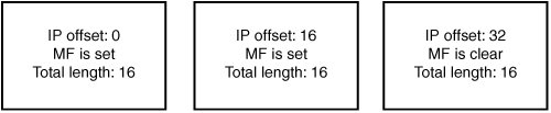
The pointer byte is related to the option length (and to the IP header length and total length) because it's supposed to point inside the option, not before or after. When auditing code that processes source routes, you should ensure that the pointer byte is within the specified bounds, especially because during processing, an IP option often modifies bytes the pointer is pointing at. Also, like the IP option length, the pointer is a single-byte field, which means type conversions such as the following could be performed on it: char *optionbytes; int offset; offset = optionbytes[2]; Code auditors need to be aware of possible sign extensions that could cause the offset integer to take on a negative value and have the offset point into a previous option, the IP header itself, or before it somewhere in memory. Such an invalid access can have serious consequences, including memory corruption, unexpected packet rerouting, or invalid memory access. Additionally, it is quite easy for developers to forget to adequately validate the length of routing options when constructing code designed to handle them, which can lead to accessing memory out of bounds. This error is especially significant for source routing options because the offset byte is often modified during options processing, when it's updated to point to the next element in the list. To give you an idea of some of the options processing bugs that have occurred in real-world applications in the past, consider this. Several years ago, a contumacious researcher working at NAI named Anthony Osborne discovered a vulnerability in the Windows IP stack related to an invalid source routing pointer. Windows hosts with multiple interfaces are normally configured to reject source routed packets. It turned out, however, that setting the pointer past the option allowed the source route to be processed. With a carefully crafted packet, an attacker could leverage multihomed Windows systems to participate in source routing attacks on firewalls. (Details of this bug are available at www.securityfocus.com/bid/646/info.) You will see in Chapter 15 that source routing is especially significant for attacking firewalls, primarily because source routed packets have one of their most basic attributes altered at each IP address in the option listthe destination address. FragmentationAs you have seen, IP datagrams can have a maximum size of 64KB. (The total length field is 16 bits, so the maximum size it can specify is 65535 bytes.) In practice, however, physical interfaces attached to routers and endpoints often impose much more limited size restrictions because they can send only fairly small frames across the network. This size restriction is dictated by what type of physical interface is sending the frame. The consequence of physical interface size restrictions is that IP datagrams can be generated for transmissions that are too large to be sent across the physical network, or IP datagrams can arrive on one interface of a router that are too large to pass across to another interface. To help deal with this problem, the IP protocol allows fragmenting large datagrams into smaller pieces so that they can be sent across any medium, regardless of its maximum transmission unit (MTU). This mechanism is called IP fragmentation. Fragmenting an IP datagram involves dividing a large datagram into smaller chunks (fragments) that are suitable for transmission. Each fragment contains a payload that constitutes some portion of the original datagram, and all fragments are transmitted separately. They are then combined (reassembled) at the destination host to re-create the original datagram. In addition to the sending host fragmenting a datagram, any intermediate routing hop can fragment a datagram (or fragment a fragment of a datagram) to be able to send it on to the destination host. No intermediate hops perform reassembly, however; that task is left up to the destination host. Note Actually, arbitrary routers that IP packets are traversing are unable to perform reassembly because IP packets aren't required to arrive at a destination via the same route. Therefore, there's no guarantee that each fragment will pass through a certain router. The exception, of course, is when fragments arrive at the network the destination host is a part of, where it's quite common to have firewalls and IPSs or IDSs perform a virtual reassembly of the received fragments to ensure that someone isn't using fragmentation to try to sneak illegal traffic through the firewall. Basic IP Fragment ProcessingFragmenting an IP packet is fairly straightforward. You split the data in a large IP packet into several smaller fragments. Each fragment is sent in a separate IP packet with its own IP header. This fragment looks the same as the original IP header, except for a few variables that tell the end host how to reassemble the fragment. The end host can tell which incoming fragments belong to the same original datagram because they all share the same IP ID (among other attributes). Specifically, each fragment for a datagram has the following fields in common: IP ID, source IP address, destination IP address, and IP protocol. A few fields are used to track how to put the fragments back together. First, if the MF ("more fragments") flag in the fragment offset field is set, the end host should expect more fragments to arrive for the datagram that have data beyond the end of the current fragment. To put it another way, if a received fragment has data starting at offset 128 from the original datagram and finishing at offset 256 and the MF bit is set for the fragment, then another fragment should arrive containing data at an offset of 256 or higher. The last fragment doesn't have the MF flag set, which tells the end host the fragment represents the end of the original IP datagram. Each fragment sets the fragment offset field to indicate where in the reassembled datagram the data from this fragment should appear. The offset field is multiplied by 8 to find out where in the completed datagram this fragment's payload should appear. So if the offset field is set to 1, the payload should appear 8 bytes into the completed datagram when it's reassembled. If the offset field is 2, the payload appears 16 bytes into the completed datagram, and so on. Finally, the total length field in the IP header is changed to represent the fragment's length. The end host determines the real total length of the original datagram by waiting until it's seen all the fragments and pieced them all together. To better understand where fragmentation might be used, consider the case where a router needs to fragment an IP datagram to send it over one of the networks it's part of, because the datagram is larger than the outgoing interface's MTU. The datagram is 3,500 bytes and the outgoing interface's MTU is 1,500 bytes, so the maximum amount of data that can be transmitted in each packet is 1,480 bytes (because the IP header is a minimum of 20 bytes). This datagram is split up into four smaller IP fragments, and they are sent over the network separately, as shown in Figure 14-2. Figure 14-2. IP fragmentation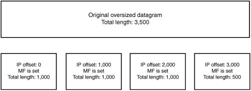 If all the fragments arrive at the destination IP address, the end host reassembles them into the original datagram. If any fragment doesn't make it, the whole datagram is discarded, and the source host is free to try to send the datagram again. Pathological Fragment SetsA normal set of fragments generally looks like Figure 14-2. All fragments except for the final one have the MF flag set. The IP offsets are laid out contiguously so that every value from 0 to the end of the final fragment is assigned data. A few subtle attacks can be performed against IP fragment reassembly code by deviating from the expected layout. The following sections describe these attacks. Data Beyond the End of the Final FragmentThe final fragment of a datagram queue has a nonzero offset, and the MF bit is clear. This fragment is supposed to contain data located at the end of the datagram, so it should have the highest IP offset of all the fragments. Attackers could send fragments in an order that puts the final fragment in the middle or beginning of the set of fragments. If the reassembly code takes certain shortcuts in calculating the datagram's total length, this reordering can lead to incomplete sets of fragments being reassembled in ways advantageous to the attackers. Consider the following reassembly code: /* Add a fragment to the queue Returns: 0: added successfully, queue incomplete 1: added successfully, queue complete */ int fragment_add(struct fragment_chain *chain, struct packet *pkt) { struct iphdr *iph = pkt->ip_header; int offset, end, length; offset = ntohs(iph->frag_offset) * 8; end = offset + ntohs(iph->tot_len) iph->hl << 2; length = add_to_chain(chain, pkt->data, offset, end); chain->datalength += length; if(!(iph->flags & IP_MF)) /* Final Fragment MF bit clear */ return chain->datalength == end; return 0; }For this example, assume that the add_to_chain() function returns the amount of data that was added to the queue, not including overlapped sections (discussed in "Overlapping Fragments" later in this chapter). When a final fragment is received, its end (offset + length) is compared with the total amount of bytes received for the datagram. If the final fragment is received last, these numbers should be equal, and the reassembly code knows it has completed reassembly of this datagram. To see how this code is intended to function, look at this valid normal set of fragments. Say you send this fragment first: Offset: 0 | MF: Set | Len: 16 The data is added to the chain, and chain->datalength is incremented to 16. MF is set, indicating more fragments, so the function returns 0 to indicate that reassembly isn't finished. Say you send this fragment next: Offset: 16 | MF: Set | Len: 16 This data is added to the chain, and chain->datalength is incremented to 16. Again, reassembly isn't complete because there are more fragments to come. Now say you send the final fragment: Offset: 32 | MF: Clear | Len: 16 When the preceding code processes this fragment, it calculates an offset of 32, an end of 48, and a length of 16. chain->datalength is incremented to 48, which is equal to end. It's the final fragment because IP_MF is clear, and chain-> datalength is equal to end. The IP stack knows it has finished reassembly, so it returns a 1. Figure 14-3 shows the set of fragments. Figure 14-3. IP fragmentation reassembly Now walk through a malicious set of fragments. This is the first fragment: Offset: 32 | MF: Set | Len: 16 The data is added to the chain, and chain->datalength is incremented to 16. MF is set, indicating there are more fragments. Next, the final fragment is sent but placed before the first fragment: Offset: 16 | MF: Clear | Len: 16 The data is added to the chain, and chain->datalength is incremented to 32. MF is clear, indicating it's the last fragment, and end is 32, which is equivalent to chain->datalength. Therefore, the IP stack believes that reassembly is complete, even though no data for offsets 0 to 16 has been sent in the set of fragments. The malicious set of fragments looks like Figure 14-4. Figure 14-4. Malicious IP fragments The result of this reassembly depends on the implementation of the rest of the IP stack. Some consequences could include the following:
Most important, any firewall or IDS/IPS this fragment chain traversed would interpret the fragments completely differently and make incorrect decisions about whether to allow or deny it (unless these devices had the same bug). Multiple Final FragmentsAnother mistake fragmentation reassembly applications make is that they don't deal with multiple final fragments correctly. Applications often assume that only one fragment of a fragment queue appears with the MF bit clear. This assumption can lead to broken logic for deciding when a fragment queue is complete and can be passed up to the next layer (usually TCP or UDP). Usually, the result of a bug like this is a fragment queue being deemed complete when it has gaps from the datagram that still haven't arrived. The advantage this type of bug gives an attacker depends on the application. For OS protocol stacks, being able to assemble a datagram with holes in it is quite useful to attackers because any firewall or IDS performing virtual reassembly interprets the datagram differently to the end host. For example, an IP datagram containing a TCP segment is fragmented and sent to a host through a firewall. Imagine that a bug exists whereby it can be marked as being complete when it's missing data at offset 0 (the beginning of the TCP header). With this knowledge, attackers could send fragments that exploit the bug as well as a trailing bogus fragment at offset 0. This bogus fragment which can be set with different TCP ports to pass a firewall's rule set. Because the firewall in front of the end host evaluates whether the fragment set is allowed based on the 0-offset fragment, it will make a policy decision based on the one part of the fragment queue that the destination host is going to completely ignore. As a resut, an unauthorized connection or block of data could be sent through the firewall. If the application containing a reassembly bug is a firewall or other security product instead of a host OS IP stack, the implications can be much worse, as this bug allows attackers to bypass firewall rules to reach any destination host that the firewall is supposed to protect (depending on the constraints of the vulnerability). Overlapping FragmentsAs you know, each IP fragment provides a portion of a complete datagram, but how to handle overlapping fragments hasn't been mentioned yet. The IP specification vaguely says that fragments can contain overlapping data ranges, which in retrospect, was probably a bad move. Figure 14-5 shows an example of overlapping fragments. Figure 14-5. Overlapping fragments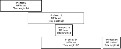 So are overlapping fragments a potential security issue? Absolutely! They add a degree of complexity to the requirements that might not seem important at first, but they have actually led to dozens of security vulnerabilities. Two main problems come into play when dealing with overlapping fragments, which are:
As discussed in Chapter 7, "Program Building Blocks," a lot of simple errors based on managing lists are quite relevant to IP fragmentation because lists are used in nearly all IP implementations to track fragments for a datagram. In Chapter 7, you saw a famous example of a vulnerability (dubbed "teardrop") that existed in a number of host IP stacks. The basis of this vulnerability was a logic error in which two fragments are sent. The first provides some arbitrary part of the datagram, and the second provides data at the same offset as the first (or at some offset partway through the data that was provided in the first one), but finishing before the end of the first one (that is, the second datagram was completely encompassed by the first). This error leads to a size calculation error that results in attempting to access memory out of bounds. The IP RFC (RFC 791) isn't much help in understanding how to deal with data overlaps. It gives a sample algorithm for handling reassembly and indicates that if two or more overlapping fragments contain the same data, the algorithm uses the "more recently arrived data." However, it doesn't specify which data an IP stack should favor: data received in the original fragment or data supplied in successive fragments. So software vendors have implemented the algorithm in different ways. Consequently, if a firewall or IDS/IPS interprets the data stream differently from the destination host, this difference opens the potential to sneak data past a security device that should detect or block it. This is especially critical when the data being overlapped includes protocol headers because they might affect whether a packet filter or firewall decides to block or forward the packet. To help you understand this problem, here's a quick outline of the key differences in major fragmentation implementations. Figure 14-6 shows a nuance of the BSD reassembly code. Figure 14-6. BSD overlap semantics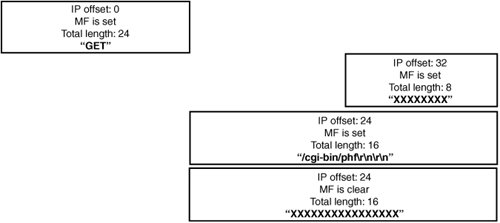 Table 14-1 shows the results of reassembling the packet set in Figure 14-6.
BSD ostensibly honors data it receives first, but this isn't what happens in practice. When BSD receives a new fragment, it left-trims the beginning of the fragment to honor previously received data, but after doing that, it accepts all the data from the new fragment. Windows and Solaris appear to honor the chronologically first data properly, but this isn't quite what occurs behind the scenes. Linux behaves similarly to BSD, but it honors a new fragment in favor of an old one if the new fragment has the same offset as the old one. Figure 14-7 shows a set of packets that isolate the Linux behavior. Figure 14-7. Linux overlap semantics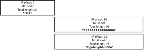 Table 14-2 shows the results of the Linux reassembly code. It performs similarly to BSD reassembly algorithms, except it honors the data in a new fragment at the same offset as a previously received one.
Figure 14-8 shows one more test case that isolates Windows behavior. Figure 14-8. Windows overlap semantics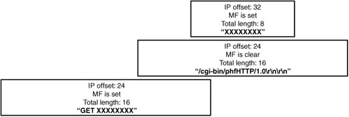 Table 14-3 shows that most implementations actually discard a fragment that's completely subsumed by a following fragment because they attempt to preserve old data by adjusting the beginning and end of fragments as they come in. As you can see, because there's some variation in reassembly algorithms, any device doing virtual reassembly interprets overlapped data segments the same way as a destination host in some situations but not in others.
Note You might think that because of this discrepancy, devices doing reassembly for security analysis are guaranteed to not work correctly when dealing with different kinds of hosts, but this isn't necessarily the case. Some implementations emulate the protocol stack of the OS for which they're reassembling traffic. Others might authoritatively rewrite packets into an unambiguous set of fragments or simply reassemble the datagram. Others might reject fragment queues containing any sort of overlap, which is usually a sign of foul play. This is exactly what Checkpoint Firewall-1's virtual reassembly layer does. IdiosyncrasiesThere are many subtle differences in how implementations handle the corner cases of fragmentation reassembly. For example, some hosts require every fragment except the last to be a multiple of 8 bytes. Some hosts accept 0-length fragments and queue them, and some don't. You've seen that hosts handle overlapping of fragmentation in different ways, and you could come up with creative test cases that just about every implementation reassembles slightly differently. Another big point of variation is the choice of timeouts and the design of data structures necessary to temporarily hold on to fragments until they are collected and ready to be reassembled. These small differences add up to potential vulnerabilities when there's a security device between the attacker and the end host. Say you have an IDS watching the network for signs of attack. An attacker could send a strange set of fragments that the IDS sees as innocuous, but the end host reassembles them into a real attack. As you discover in Chapter 15, the same kind of ambiguity can come into play when attacking firewalls, although the attacks are less straightforward. |
EAN: 2147483647
Pages: 194