An Extended Example
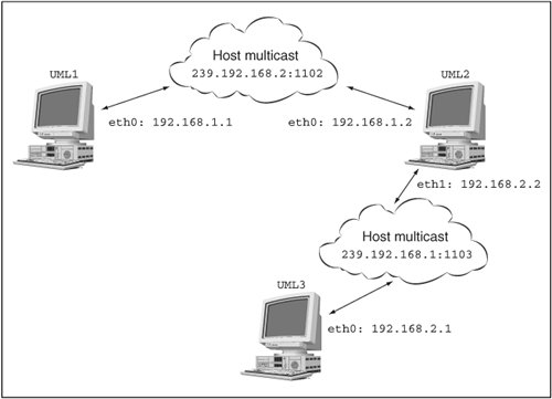
| Now that we've covered most of what there is to know about setting up UML networking, I am going to show off some of how it works. This extended example involves multiple UML instances. To simplify their launching, I will assign them unique filesystems by giving them different COW files with the same backing file and by giving each a different umid. So, the command line of the first one will have this: ubda=cow1,../..debian30 umid=debian1 and the second will have this: ubda=cow2,../..debian30 umid=debian2 You'll probably want to do something similar as you follow along. I will be hot-plugging all network interfaces, so those won't be on the command lines. A Multicast NetworkTo start, I'll run two UML instances like this. We'll begin the networking with the simplest virtual networka default multicast network. So, let's plug a multicast device into both: host% uml_mconsole debian1 config eth0=mcast OK host% uml_mconsole debian2 config eth0=mcast OK The kernel log of each instance shows something like this: Configured mcast device: 239.192.168.1:1102-1 Netdevice 0 : mcast backend multicast address: \ 239.192.168.1:1102, TTL:1 You can see this by running dmesg, and it may also appear on the main console, depending on the distribution you are running. Now, let's bring up both UML instances. I'm using the 192.168.1.0/24 network to keep the virtual network separate from my physical network since I intend to hook this network up to the host later. So, the first one is 192.168.1.1: UML1# ifconfig eth0 192.168.1.1 up and the second is 192.168.1.2: UML2# ifconfig eth0 192.168.1.2 up Figure 7.1 shows what we have set up so fartwo UML instances on the 192.168.1.0 network connected by the host's multicast network. Figure 7.1. A single multicast network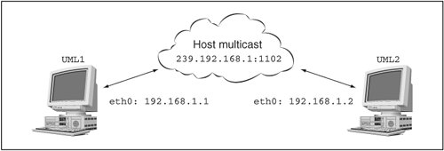 Now, check connectivity in one direction: UML1# ping 192.168.1.2 PING 192.168.1.2 (192.168.1.2): 56 data bytes 64 bytes from 192.168.1.2: icmp_seq=0 ttl=64 time=0.4 ms 64 bytes from 192.168.1.2: icmp_seq=1 ttl=64 time=0.3 ms 64 bytes from 192.168.1.2: icmp_seq=2 ttl=64 time=0.3 ms --- 192.168.1.2 ping statistics --- 3 packets transmitted, 3 packets received, 0% packet loss round-trip min/avg/max = 0.3/0.3/0.4 ms Pinging in the other direction will show something similar. A Second Multicast NetworkNow, let's set up a second, partially overlapping multicast network. This will demonstrate the use of nondefault multicast parameters. It will also make us set up some routing in order to get the two UMLs that aren't on the same network to talk to each other. This calls for launching a third UML instance, which will get a third COW file and umid, with this on its command line: ubda=cow3,../..debian30 umid=debian3 Let's put the second and third instances on the new multicast network: host% uml_mconsole debian2 config eth1=mcast,,239.192.168.2,1103 OK host% uml_mconsole debian3 config eth0=mcast,,239.192.168.2,1103 OK The second instance's etH1 and the third instance's eth0 are now on this new network, which is defined by being on the next multicast IP and the next port. Now, we configure them on a different subnet: UML2# ifconfig eth1 192.168.2.2 up and UML3# ifconfig eth0 192.168.2.1 up Figure 7.2 shows our network so far. Figure 7.2. Two multicast networks
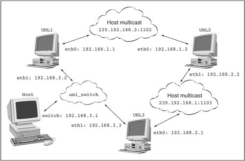
Testing connectivity here shows us what we expect: UML3# ping 192.168.2.2 PING 192.168.2.2 (192.168.2.2): 56 data bytes 64 bytes from 192.168.2.2: icmp_seq=0 ttl=64 time=25.7 ms 64 bytes from 192.168.2.2: icmp_seq=1 ttl=64 time=0.4 ms --- 192.168.2.2 ping statistics --- 2 packets transmitted, 2 packets received, 0% packet loss round-trip min/avg/max = 0.4/13.0/25.7 ms Now, let's ping the first UML from the third: UML3# ping 192.168.1.1 PING 192.168.1.1 (192.168.1.1): 56 data bytes ping: sendto: Network is unreachable ping: wrote 192.168.1.1 64 chars, ret=-1 ping: sendto: Network is unreachable ping: wrote 192.168.1.1 64 chars, ret=-1 --- 192.168.1.1 ping statistics --- 2 packets transmitted, 0 packets received, 100% packet loss The third UML has no idea how to reach that other network. So, we need to do some routing: UML3# route add -net 192.168.1.0/24 gw 192.168.2.2 Retrying the ping gives us different behaviordead silence: ping 192.168.1.1 PING 192.168.1.1 (192.168.1.1): 56 data bytes --- 192.168.1.1 ping statistics --- 4 packets transmitted, 0 packets received, 100% packet loss Let's watch tcpdump on the second UML instance to learn what traffic it sees: UML2# tcpdump -i eth1 -l -n device eth1 entered promiscuous mode tcpdump: listening on eth1 02:06:28.795435 192.168.2.1 > 192.168.1.1: icmp: echo \ request (DF) 02:06:29.820703 192.168.2.1 > 192.168.1.1: icmp: echo \ request (DF) 02:06:30.848753 192.168.2.1 > 192.168.1.1: icmp: echo \ request (DF) This is fine; ping requests are reaching the gateway between the two networks. Next, the pings should be sent out through eth1 to the target UML instance: # tcpdump -i eth0 -l -n device eth0 entered promiscuous mode tcpdump: listening on eth0 0 packets received by filter 0 packets dropped by kernel device eth0 left promiscuous mode They're not. This is a big clue to something we saw on the hostgenerally, Linux systems aren't set up as gateways and need to be told to forward packets when they can: UML2# echo 1 > /proc/sys/net/ipv4/ip_forward Let's look at the gateway instance's eth0 again while the ping is running: UML2# tcpdump -i eth0 -l -n device eth0 entered promiscuous mode tcpdump: listening on eth0 02:09:45.388353 192.168.2.1 > 192.168.1.1: icmp: echo \ request (DF) 02:09:45.389009 192.168.2.1 > 192.168.1.1: icmp: echo \ request (DF) 02:09:46.415998 192.168.2.1 > 192.168.1.1: icmp: echo \ request (DF) 02:09:46.416025 192.168.2.1 > 192.168.1.1: icmp: echo \ request (DF) 02:09:47.432823 192.168.2.1 > 192.168.1.1: icmp: echo \ request (DF) 02:09:47.432854 192.168.2.1 > 192.168.1.1: icmp: echo \ request (DF) 6 packets received by filter 0 packets dropped by kernel device eth0 left promiscuous mode Now pings are going out the gateway's eth0. We should look at the target's eth0: UML1# tcpdump -i eth0 -l -n device eth0 entered promiscuous mode tcpdump: listening on eth0 02:12:36.599365 192.168.2.1 > 192.168.1.1: icmp: echo \ request (DF) 02:12:37.631098 192.168.2.1 > 192.168.1.1: icmp: echo \ request (DF) 2 packets received by filter 0 packets dropped by kernel device eth0 left promiscuous mode Nothing but requests here. There should be replies, but there aren't. This is the same problem we saw on the pinging UMLit doesn't know how to reply to the other network. A new route will fix this: UML1# route add -net 192.168.2.0/24 gw 192.168.1.2 If you left the ping running, you'll see it immediately start getting replies at this point. Now, we have three UML instances on two virtual networks, with one UML acting as a gateway between the two and with routing set up so that all three instances can communicate with each other. I'm running ping only to test connectivity, but it is fun to ssh between them and to fetch Web pages from one to another. Adding a uml_switch NetworkLet's bring the virtual switch into the action, and with it, the host. First, we'll set up a TUN/TAP device for the switch to communicate with the host: host% tunctl -t switch Set 'switch' persistent and owned by uid 500 host# ifconfig switch 192.168.3.1 up Now let's run the switch using a nondefault socket: host% uml_switch -unix /tmp/switch.sock -tap switch uml_switch attached to unix socket '/tmp/switch.sock' \ tap device 'switch' New connection Addr: 86:e5:03:6f:7e:49 New port 5 It fakes a new connection to itself when it attaches to the TUN/TAP device. You'll see the same sorts of messages when we plug interfaces into the UML instances. I'll attach UML1 and UML3 to the switch: host% uml_mconsole debian1 config eth1=daemon,,unix,\ /tmp/switch.sock OK host% uml_mconsole debian3 config eth1=daemon,,unix,\ /tmp/switch.sock OK You'll see a message like this in each instance: Netdevice 1 : daemon backend (uml_switch version 3) - \ unix:/tmp/switch.sock Let's bring these up on the 192.168.3.0/24 network: UML1# ifconfig eth1 192.168.3.2 up UML3# ifconfig eth1 192.168.3.3 up These are getting 192.168.3.2 and 192.168.3.3 because 192.168.3.1 was assigned to the TUN/TAP device. Figure 7.3 shows our growing network. Figure 7.3. Three networks
As usual, let's check connectivity, this time through the switch: UML3# ping 192.168.3.2 PING 192.168.3.1 (192.168.3.1): 56 data bytes 64 bytes from 192.168.3.1: icmp_seq=0 ttl=64 time=26.8 ms 64 bytes from 192.168.3.1: icmp_seq=1 ttl=64 time=0.2 ms 64 bytes from 192.168.3.1: icmp_seq=2 ttl=64 time=0.2 ms 64 bytes from 192.168.3.1: icmp_seq=3 ttl=64 time=0.2 ms --- 192.168.3.1 ping statistics --- 4 packets transmitted, 4 packets received, 0% packet loss round-trip min/avg/max = 0.2/6.8/26.8 ms You'll get something similar if you ping in the other direction. Some chatter from the switch occurs as you configure the devices and run ping: New connection New connection Addr: fe:fd:c0:a8:03:02 New port 7 Addr: fe:fd:c0:a8:03:01 New port 6 Addr: d2:a1:c9:78:bd:d7 New port 5 The New connection message is printed whenever a new device is attached to the switch, whether it's a UML instance or a host TUN/ TAP interface. This is the equivalent of plugging something new into a physical switch. The New connection message is more or less equivalent to the link light on that port. Messages such as Addr: fe:fd:c0:a8:03:02 New port 7 are printed whenever the switch sees a new Ethernet MAC on a port. The address is self-explanatory. The port is the file descriptor over which the switch is communicating with the other device. Physical switches have a fixed number of ports, but this virtual switch is limited only by the number of file descriptors it can have open. These messages will be repeated periodically as the switch does garbage collection and throws out MACs that haven't been seen recently. When the connection later wakes up, as the UML refreshes its arp cache or something similar, the switch will remember the MAC again and print another message to that effect. At this point, we should have access to the host from the first and third UML instances through the TUN/TAP device attached to the switch: UML3# ping 192.168.0.2 PING 192.168.0.2 (192.168.0.2): 56 data bytes ping: sendto: Network is unreachable ping: wrote 192.168.0.2 64 chars, ret=-1 --- 192.168.0.2 ping statistics --- 1 packets transmitted, 0 packets received, 100% packet loss Well, not quite, but we've seen this message before, and we know what to do about it: UML1# route add -net 192.168.0.0/24 gw 192.168.3.1 UML3# route add -net 192.168.0.0/24 gw 192.168.3.1 This is setting the gateway to the 192.168.3.0/24 network to be the switch TUN/TAP device. This ensures that packets to this network are addressed to the TUN/TAP device so that the switch routes them appropriately. Once they've reached the TUN/TAP device, they are on the host, and the host will deal with them as it sees fit. At this point, the first and third UML instances have connectivity with the host: UML3# ping 192.168.0.2 PING 192.168.0.2 (192.168.0.2): 56 data bytes 64 bytes from 192.168.0.2: icmp_seq=0 ttl=64 time=26.4 ms 64 bytes from 192.168.0.2: icmp_seq=1 ttl=64 time=0.2 ms 64 bytes from 192.168.0.2: icmp_seq=2 ttl=64 time=0.2 ms --- 192.168.0.2 ping statistics --- 3 packets transmitted, 3 packets received, 0% packet loss round-trip min/avg/max = 0.2/8.9/26.4 ms The second UML instance has no access to the host because it is attached only to the two virtual networks. So, let's fix that by having it route packets through the third UML. We've done part of this already. We can finish it by enabling IP forwarding on the gateway and routing on the second UML: UML3# echo 1 > /proc/sys/net/ipv4/ip_forward UML2# route add -net 192.168.3.0/24 gw 192.168.2.1 UML2# route add -net 192.168.0.0/24 gw 192.168.2.1 Rather than adding two routes, it would also work to specify 192.168.2.1 as the default gateway for UML2. The gateway is set to 192.168.2.1 since that's the IP address that the gateway UML has on the 192.168.2.0/24 network. The ping doesn't work: UML2# ping 192.168.0.2 PING 192.168.0.2 (192.168.0.2): 56 data bytes --- 192.168.0.2 ping statistics --- 115 packets transmitted, 0 packets received, 100% packet loss Now we have to go through the usual tcpdump exercise. Running tcpdump on the gateway's eth0 tells us whether the requests are showing up: UML3# tcpdump -i eth0 -l -n device eth0 entered promiscuous mode tcpdump: listening on eth0 16:37:19.634422 192.168.2.2 > 192.168.0.2: icmp: echo \ request (DF) 16:37:20.654462 192.168.2.2 > 192.168.0.2: icmp: echo \ request (DF) 16:37:21.683267 192.168.2.2 > 192.168.0.2: icmp: echo \ request (DF) 3 packets received by filter 0 packets dropped by kernel They are, so let's make sure they are being forwarded to etH1 so they reach the switch: UML3# tcpdump -i eth1 -l -n device eth1 entered promiscuous mode tcpdump: listening on eth1 16:37:24.738960 192.168.2.2 > 192.168.0.2: icmp: echo \ request (DF) 16:37:25.768702 192.168.2.2 > 192.168.0.2: icmp: echo \ request (DF) 16:37:26.697330 arp who-has 192.168.3.1 tell 192.168.3.3 16:37:26.697483 arp reply 192.168.3.1 is-at d2:a1:c9:78:bd:d7 16:37:26.787541 192.168.2.2 > 192.168.0.2: icmp: echo \ request (DF) 16:37:27.818978 192.168.2.2 > 192.168.0.2: icmp: echo \ request (DF) 16:37:28.839216 192.168.2.2 > 192.168.0.2: icmp: echo \ request (DF) 7 packets received by filter 0 packets dropped by kernel device eth1 left promiscuous mode So far, so good. The next interface the packets should reach is the switch TUN/TAP interface, so let's go to the host and tcpdump that: host# tcpdump -i switch -l -n tcpdump: verbose output suppressed, use -v or -vv for full \ protocol decode listening on switch, link-type EN10MB (Ethernet), capture \ size 96 bytes 12:44:31.851022 arp who-has 192.168.3.1 tell 192.168.3.3 12:44:32.208988 arp reply 192.168.3.1 is-at d2:a1:c9:78:bd:d7 12:44:32.209001 IP 192.168.2.2 > 192.168.0.2: icmp 64: echo \ request seq 0 12:44:32.817880 IP 192.168.2.2 > 192.168.0.2: icmp 64: echo \ request seq 256 12:44:33.846666 IP 192.168.2.2 > 192.168.0.2: icmp 64: echo \ request seq 512 12:44:34.875457 IP 192.168.2.2 > 192.168.0.2: icmp 64: echo \ request seq 768 6 packets captured 6 packets received by filter 0 packets dropped by kernel Here's the problemping requests are reaching the host, but no replies are being sent back. The reason is that the host doesn't have a route back to the 192.168.2.0/24 network: host% route -n Kernel IP routing table Destination Gateway Genmask Flags Metric \ Ref Use Iface 192.168.3.0 0.0.0.0 255.255.255.0 U 0 \ 0 0 switch 192.168.0.0 0.0.0.0 255.255.255.0 U 0 \ 0 0 eth0 169.254.0.0 0.0.0.0 255.255.0.0 U 0 \ 0 0 eth1 0.0.0.0 192.168.0.1 0.0.0.0 UG 0 \ 0 0 eth1 We didn't need to add a route for 192.168.3.0/24 because we got one automatically when we assigned the 192.168.3.1 address to the switch TUN/TAP device. We need to manually add a route for the 192.168.2.0/24 network because that's hidden behind the switch, and the host can't see it directly. So, let's add one and see if this changes anything: host# route add -net 192.168.2.0/24 gw 192.168.3.3 UML2# ping 192.168.0.2 PING 192.168.0.2 (192.168.0.2): 56 data bytes 64 bytes from 192.168.0.2: icmp_seq=0 ttl=63 time=0.5 ms 64 bytes from 192.168.0.2: icmp_seq=1 ttl=63 time=0.4 ms --- 192.168.0.2 ping statistics --- 2 packets transmitted, 2 packets received, 0% packet loss round-trip min/avg/max = 0.4/0.4/0.5 ms For good measure, since this is the most complicated routing we have done so far, let's check pinging in the other direction: ping 192.168.2.2 PING 192.168.2.2 (192.168.2.2) 56(84) bytes of data. 64 bytes from 192.168.2.2: icmp_seq=0 ttl=63 time=16.2 ms 64 bytes from 192.168.2.2: icmp_seq=1 ttl=63 time=0.369 ms --- 192.168.2.2 ping statistics --- 2 packets transmitted, 2 received, 0% packet loss, time 1001ms rtt min/avg/max/mdev = 0.369/8.295/16.221/7.926 ms, pipe 2 Summary of the Networking ExampleWe've grown a fairly complicated network during this example, so before shutting everything down, it's useful to recap what we've done. We now have three UMLs and three two-node networks:
UML2 is acting as the gateway between the two multicast networks, 192.168.1.0/24 and 192.168.2.0/24. UML3 is acting as the gateway between the 192.168.2.0/24 multicast network and the uml_switch network. The gateway UMLs need to have IP forwarding enabled so they will forward packets that are not addressed to them. The UMLs that are not directly attached to a network need a route to that network through the gateway UML. Finally, the host needs a route for any networks it is not directly attached to. |