Linux-Based Graphic Design Tools
| The open source community has developed a wide variety of Linux-based graphic design tools for mapping networks. However, from the perspective of creating Cisco-based network diagrams, the choices are limited. On the basis of popularity and communitywide support, the following two tools are worth mentioning:
Dia is an open source program for creating diagrams. Dia can be used to draw many different kinds of diagrams, including network diagrams and flow charts. The project home page for Dia is located at http://www.gnome.org/projects/dia/. The following advantages are offered by Dia:
This chapter discusses Dia rather than Kivio because Kivio stencils are not free. Dia stencils are available at no charge and can be distributed freely. This following sections prepare the Netadmin for understanding and using Dia:
Deploying DiaThe steps involved in deploying Dia are as follows:
Creating Diagrams with DiaBefore creating a network diagram, you should be familiar with the toolbar and the various icons used in Dia. The main window shows the toolbar menu (as shown in Figure 11-1), which consists of three sections:
Figure 11-1. Dia Toolbar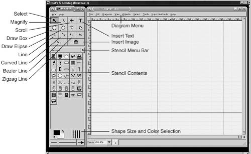 The top section of the toolbar menu consists of connectors and standard shapes. The middle section contains a drop-down menu for stencils. The contents of the selected stencil are displayed below the menu bar. The bottom section consists of the selector for shape, size, and colors. The Diagram pane uses its own menu. Dia refers to the stencils as sheets. Each sheet contains icons. Dia refers to icons as shapes. The six most useful sheets for network diagrams, which are preloaded in Dia, are as follows:
To start a new diagram, choose File > New. If the diagram lacks the File menu at the top, you can right-click within the blank area of the diagram to invoke the Diagram file menu. Tip By default, the display is not antialiased, causing the icons to look fuzzy. To turn on the Antialiasing feature, choose View > AntiAliased on the Diagram menu. The most common tasks involved in creating a network diagram using Dia are as follows:
These are only a few of the most common tasks available to the Netadmin. For more information, refer to the online manual that is included with the installation files. To view the manual, choose Help > Manual in the Diagram pane. Adding IconsOn the main toolbar, choose the desired sheet from the drop-down menu to display the icons. Drag the desired icon and drop it on the diagram. The blue cross signs (X) on the edge of the icons are the connection points. To toggle the display of connection points, choose View > Show Connection Point on the Diagram menu. Connecting IconsTo connect two icons, click to select the desired link from the upper section of main toolbar. The choices are straight line, curved line, zigzag line, and polyline. Click the drawing to drop the selected link. Select and drag the green ends of the link and drop it over the connection point on the icon. The link snaps to the icon only if the end of the link overlaps the connection point on the icon. Dia displays a red boundary around the icon when the connection point overlaps the end of the link. Removing a ConnectionTo remove a connection, click the link and press Delete. Adding a Text BoxTo insert a text box containing information such as host name or IP address, click the Insert Text button on the main toolbar and then click the desired location on the diagram. Enter the desired text. Click the blank background to exit the Insert Text mode. Inserting an Ethernet BackboneTo insert an Ethernet backbone, select the Network stencil from the stencil drop-down menu on the main toolbar. Drag and drop the Ethernet icon on the diagram. You can also insert a serial line link using the Network stencil. Exporting the Diagram as a JPEG ImageTo save the image in PNG or JPEG format, follow these steps:
Adding a New Icon to the StencilThis feature is handy for adding new icons that are not part of the standard shapes included in Dia. To add new icons, follow these steps:
Tip You can find a variety of Cisco icons at the home page of the Cisco Packet magazine: http://www.cisco.com/go/packet. You can also use these icons with OpenOffice Draw to create simple network diagrams. Viewing Sample Dia DiagramsThe following are three sample diagrams created by Dia. Figure 11-2 shows Dia in action, drawing a logical topology for ABC Investments Inc. Figure 11-2. Dia in Action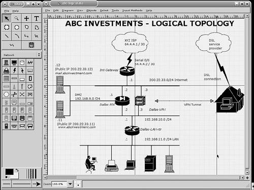 Figure 11-3 shows the final output in .jpg format. Figure 11-3. Dia JPEG output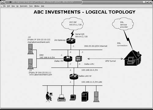 Figure 11-4 represents the physical topology of the network shown in Figure 11-3. Note the differences in physical versus logical topologies. Figure 11-4. Dia Physical Topology |
EAN: 2147483647
Pages: 106