Configuring Routing Between VLANs
| Configuring routing for the Catalyst 3550 switch is similar to configuring any Cisco router because all three use a similar IOS-based interface. This section covers basic inter-VLAN routing with an internal RP (Catalyst 3550 switch) and an external RP. The purpose of this material is not to cover all the routing commands you can execute or configure within the IOS, but rather to show you how to configure the IOS to support inter-VLAN routing. It's assumed that you are familiar with configuring Cisco routers and their command-line interface (CLI).
Configuring an Internal RPYou'll first need to access the CLI of your switch. I'm assuming that you're using a Catalyst 3550 switch. You'll set up routing in two steps. First, configure Layer 2 connectivity by creating your VLANs and placing ports in them. This was discussed in Chapter 3. Second, set up Layer 3 connectivity by creating VLAN interfaces and enabling a routing protocol. Before you begin your Layer 3 setup, you'll first need to configure your Layer 2 information. This includes creating your VLANs, placing ports in them, creating trunks, and tuning STP. Types of Switch InterfacesThe switch's interfaces can operate in various modes, which are as follows:
If you recall from Chapter 3, an access port is a Layer 2 interface associated with a single VLAN. End user devices are typically connected to this port. But you can also connect routers and other switches. This is set with the switchport mode access command on the specific interface. If you recall from Chapter 3, a trunk port is a Layer 2 interface capable of carrying traffic for multiple VLANs. Each frame is tagged with the source's VLAN number. Cisco supports two trunking modes: Cisco's ISL and IEEE 802.1Q. Other switches can be connected to this port as well as routers. This is set with the switchport mode trunk command on the specific interface. A routed port is a port on the switch where its behavior is changed from a Layer 2 interface to a Layer 3. In a Layer 3 mode, the interface acts like an interface on a router. You would typically set up a port as a routed port if you need to directly connect your switch to a router, and you want to make the switch appear as a router (not a switch) to its connected neighboring router. You'll first have to enable IP routing with the ip routing command. Next, configure the appropriate Layer 2 port as a routed port, enter the interface, and disable Layer 2 functions with the no switchport command. Then assign an IP address to it with the ip address command. To route between routed interfaces, you'll have to enable a routing protocol with the router command. An SVI interface is a logical interface on the switch. This interface is similar to a loopback interface on a router. A loopback interface is an imaginary interface on a router that is always in an up-and-up state. Loopback interfaces are typically used for testing purposes as well as terminating connections on the router. On the switch, a virtual interface is typically used to associate the switch's personal IP address with a VLAN (placing it in a management VLAN). This is accomplished by creating a VLAN with the vlan command, creating the virtual interface with the interface vlan command, and then assigning an IP address to it with the ip address command. Only one SVI can be associated to each VLAN. SVIs can also be used to handle internal routing on the switch. If you want to enable Layer 3 routing on your switch, use the ip routing command and enable a routing protocol with the router command.
Routing Configuration on a SwitchTo configure routing on your IOS Catalyst switch, use the following commands as shown in Listing 6.1. Listing 6.1 IOS Catalyst Configuration CommandsSwitch(config)# ip routing Switch(config)# router routing_protocol [options] Switch(config-router)# network network_# [options] Switch(config-router)# exit Switch(config)# vlan VLAN_# Switch(config)# interface vlan VLAN_# Switch(config-if)# ip address IP_address subnet_mask Switch(config-if)# no shutdown
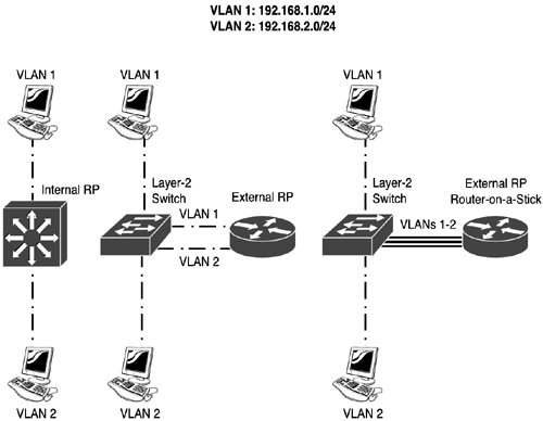
First, enable IP routing on your Catalyst switch with the ip routing command. Next, configure a routing protocol with the router and network commands. The network commands should include the IP addresses configured on your SVI interfaces. For each VLAN that you've already created on your Catalyst switch, you'll have to create a separate VLAN interface (interface vlan). The interface number must match the number of the corresponding VLAN. When within the SVI, configure your Layer 3 addressing information as well as bring the interface up with the no shutdown command. The VLAN interface will remain "administratively down" until you execute this command. Remember to save your configuration with the copy running-config startup-config Privilege EXEC command. Let's look at an example to clarify this configuration. I'll use the network shown on the left side of Figure 6.1. In this example, the Catalyst switch is performing the routing function. I'll assume that RIP is the routing protocol that this switch is running. Figure 6.1. Internal and external RP routing example.
The routing configuration for the switch is shown in Listing 6.2. Listing 6.2 Routing for an Internal RPSwitch(config)# ip routing Switch(config)# router rip Switch(config-router)# network 192.168.1.0 Switch(config-router)# network 192.168.2.0 Switch(config-router)# exit Switch(config)# vlan 1 Switch(config)# vlan 2 Switch(config)# interface vlan 1 Switch(config-if)# ip address 192.168.1.1 255.255.255.0 Switch(config-if)# no shutdown Switch(config-if)# exit Switch(config)# interface vlan 2 Switch(config-if)# ip address 192.168.2.1 255.255.255.0 Switch(config-if)# no shutdown Switch(config-if)# end Switch# copy running-config startup-config In this example, the ip routing command enables IP routing and the router rip and network statements include VLAN 1 and VLAN 2 for routing. The two vlan commands create VLAN 1 and VLAN 2. The two SVI interfaces have an IP address configured on them and have been enabled. Remember that devices in VLAN 1 and 2 should use these IP addresses as their respective default gateway addresses. Configuring an External RPThere are two ways to set up an external RP: traditional (normal) router setup and a router-on-a-stick setup. The following two sections cover both methods of configuration. Traditional Router SetupWith a traditional, or normal, router setup, your router has access connections to the switch. Therefore, for each VLAN that the router will be routing for, the router will need a separate access connection. For instance, if you have five VLANs, your router will need five Ethernet interfaces. The middle part of Figure 6.1 shows a traditional router setup. When setting up a traditional router for routing, on your switch, you'll need to configure all of your router connections as access links. You'll need to assign each of these interfaces to the appropriate VLAN this was discussed in Chapter 3. When this is done, you'll need to configure your router. Here's a simple configuration of a router using RIP for the middle network, as shown in Figure 6.1 and Listing 6.3. Listing 6.3 Routing for an External RPRouter(config)# router rip Router(config-router)# network 192.168.1.0 Router(config-router)# network 192.168.2.0 Router(config-router)# exit Router(config)# interface ethernet 0 Router(config-if)# ip address 192.168.1.1 255.255.255.0 Router(config-if)# no shutdown Router(config-if)# exit Router(config)# interface ethernet 1 Router(config-if)# ip address 192.168.2.1 255.255.255.0 Router(config-if)# no shutdown Router(config-if)# end Router# copy running-config startup-config There are two important differences when comparing this example to the internal RP example. First, notice that there is no ip routing command that's because IP routing is enabled, by default, on Cisco routers. Second, the IP addressing configuration is done on the appropriate physical Ethernet interfaces; because there are two VLANs, you need two interfaces. Router-on-a-Stick SetupOne problem with a traditional router setup is that it doesn't scale very well. The more VLANs you have, the more interfaces you need on your router. This solution becomes very costly when you reach 5 or 10 interfaces you need Cisco's higher-end routers to provide this number of interfaces. To solve this problem, you can use a router-on-a-stick. The right side of Figure 6.1 shows an example of a router-on-a-stick. In this example, there is a trunk connection between the router and the switch. The trunk is terminated on the router on a trunk-capable interface. Not all Cisco routers support trunking. For instance, the 1750 and higher routers, with the correct interfaces, support trunking. 802.1Q and ISL are supported on the routers, but ISL is supported only on Fast Ethernet or faster ports.
Configuring a router-on-a-stick requires you to first configure the interface on the switch that the router is connected to as a trunk connection. After this is done, you need to configure your router. The configuration of the router is done in a slightly different way than the traditional method. With the traditional method, you use a separate interface for each VLAN. With a router-on-a-stick, you use the same physical interface. However, to process VLAN information correctly, you'll have to take the router's trunking interface and break it up into multiple subinterfaces. A subinterface is a logical interface associated with a physical interface. Certain things, such as duplexing and speed, are configured on the physical interface. However, Layer 3 addressing and VLAN information are configured on the subinterfaces. Here's a breakdown of the commands you'd use to set up a router-on-a-stick, as shown in Listing 6.4. Listing 6.4 Routing for a Router-on-a-StickRouter(config)# router routing_protocol [options] Router(config-router)# network network_# [options] Router(config-router)# exit Router(config)# interface type slot_#/port_# Router(config-if)# [no] full-duplex Router(config-if)# no shutdown Router(config-if)# exit Router(config)# interface type slot_#/port_#.subinterface_# Router(config-if)# ip address IP_address subnet_mask Router(config-if)# encapsulation isl|dot1q VLAN_# On the physical interface, you'll want to configure your interface characteristics, such as duplexing and speed, and then enable the physical interface with the no shutdown command. The rest of the configuration will be done on subinterfaces one subinterface per VLAN. Next, create your subinterface. This is done by specifying the physical interface and following it with a period and then a subinterface number. A common convention is to use the VLAN number as the subinterface number; however, these two numbers have nothing in common and you can use any unique subinterface number. To associate a VLAN to a subinterface, use the encapsulation isl command followed by the VLAN number associated with the subinterface. If the preceding trunk is using 802.1Q, you would replace the isl encapsulation parameter with dot1q. You do not need to enable the subinterfaces: They're automatically enabled when you create them (assuming that the physical interface is enabled). However, you can shut down an individual subinterface without affecting the rest of the processing on the other subinterfaces.
Based on the network example shown on the right side of Figure 6.1, here's the RP's configuration, shown in Listing 6.5. Listing 6.5 Router-on-a-Stick ExampleRouter(config)# router rip Router(config-router)# network 192.168.1.0 Router(config-router)# network 192.168.2.0 Router(config-router)# exit Router(config)# interface fastethernet 0/0 Router(config-if)# full-duplex Router(config-if)# no shutdown Router(config-if)# exit Router(config)# interface fastethernet 0/0.1 Router(config-if)# encapsulation dot1q 1 Router(config-if)# ip address 192.168.1.1 255.255.255.0 Router(config-if)# exit Router(config)# interface fastethernet 0/0.2 Router(config-if)# encapsulation dot1q 2 Router(config-if)# ip address 192.168.2.1 255.255.255.0 Router(config-if)# end Router# copy running-config startup-config Verifying Your Routing ConfigurationWhen you've completed your routing configuration on your RP, you can test it by going to a client in one of the VLANs (including the switch), and using the ping command. For that matter, you can use the ping command from the RP to ensure that the RP can see devices in all of its connected VLANs. To examine which routing protocols are running on your RP, as well as their configurations, use the show ip protocols command. Here's an example: Router# show ip protocols Routing Protocol is "rip" Sending updates every 30 seconds, next due in 5 seconds Invalid after 180 seconds, hold down 180, flushed after 240 Outgoing update filter list for all interfaces is not set Incoming update filter list for all interfaces is not set Redistributing: rip Default version control: send version 1, receive any version Interface Send Recv Key-chain Vlan1 1 1 2 Vlan1 1 1 2 Routing for Networks: 192.168.1.0 192.168.2.0 Routing Information Sources: Gateway Distance Last Update 192.168.2.2 120 00:00:22 Distance: (default is 120) The preceding example is output from an internal RP notice the VLAN interfaces in the middle of the display. To see the IP routing table on the RP, use the show ip route command. Here's an example: Router# show ip route Codes: C - connected, S - static, I - IGRP, R - RIP, M - mobile, B - BGP, D - EIGRP, EX - EIGRP external, O - OSPF, IA - OSPF inter area, N1 - OSPF NSSA external type 1, N2 - OSPF NSSA external type 2, E1 - OSPF external type 1, E2 - OSPF external type 2, E - EGP, i - IS-IS, L1 - IS-IS level-1, L2 - IS-IS level-2, * - candidate default, U - per-user static route, o - ODR, T - traffic engineered route Gateway of last resort is not set 192.168.1.0/24 is subnetted, 1 subnets C 192.168.1.0 is directly connected, Vlan1 192.168.2.0/24 is subnetted, 1 subnets C 192.168.2.0 is directly connected, Vlan2 172.16.0.0/16 is subnetted, 2 subnets R 172.16.1.0 [120/1] via 192.168.1.2, 00:00:31, Vlan1 R 172.16.2.0 [120/1] via 192.168.1.2, 00:00:31, Vlan1 In this example, the internal RP is learning about two remote RIP routes from a neighboring RP (192.168.1.2). |
EAN: 2147483647
Pages: 171